Climax Technology Co ML Smart Home Alarm System User Manual
Climax Technology Co Ltd Smart Home Alarm System
Users Manual
Vesta
Smart Home Alarm System
MLx-xxx Series
(x=0~9, A~Z or blank)

Table of Contents
1. Application Overview__________________________________________________ 1
1.1. Parts Identification _______________________________________________________ 1
1.2. The Power Supply________________________________________________________ 5
1.3. How to Install the Control Panel ____________________________________________ 5
1.4. Multi-User Passwords ____________________________________________________ 5
1.5. System Basic Operation___________________________________________________ 6
1.6. Getting Started __________________________________________________________ 6
2. System Configuration _________________________________________________ 7
2.1. Walk Test _______________________________________________________________ 7
2.2. Install Code _____________________________________________________________ 7
2.3. Report Setting ___________________________________________________________ 7
2.4. Test Report _____________________________________________________________ 8
2.5. Test Siren_______________________________________________________________ 8
2.6. Record Message _________________________________________________________ 8
2.7. Play Message ___________________________________________________________ 8
2.8. Panel Setting ____________________________________________________________ 9
2.9. General Setting _________________________________________________________ 12
2.10. Device +/- _____________________________________________________________ 14
2.11. Network Setting________________________________________________________ 18
2.12. Media Upload__________________________________________________________ 19
2.13. Home Automation______________________________________________________ 20
3. Programming Menu __________________________________________________ 20
3.1. Walk Test ______________________________________________________________ 21
3.2. PIN Code Setting________________________________________________________ 21
3.3. Master Code ___________________________________________________________ 21
3.4. Temporary Code ________________________________________________________ 21
3.5. Duress Code ___________________________________________________________ 22
3.6. General Setting _________________________________________________________ 22
3.7. Device +/- ______________________________________________________________ 22
4. Operation __________________________________________________________ 22
4.1. LCD Display____________________________________________________________ 22
4.2. Entering User Menu _____________________________________________________ 23
4.3. Away Arm Mode ________________________________________________________ 23
4.4. Home Arm 1/2/3 Mode ___________________________________________________ 23
4.5. Force Arm _____________________________________________________________ 24
4.6. Disarm ________________________________________________________________ 24
4.7. Temporary Bypass ______________________________________________________ 24
4.8. Apply Scene ___________________________________________________________ 24
4.9. Dual Key Alarm _________________________________________________________ 25
4.10. Alarm Activation _______________________________________________________ 25
4.11. Two-Way Communication _______________________________________________ 25
4.12. Keypad Lockdown _____________________________________________________ 26
4.13. Tamper Protection _____________________________________________________ 26
4.14. Fault Display __________________________________________________________ 27
4.15. Remote Access ________________________________________________________ 27
4.16. Factory Reset _________________________________________________________ 28
4.17. Control Panel Mode & Response Table ____________________________________ 29
5. Appendix___________________________________________________________ 32
5.1. Event Code ____________________________________________________________ 32
1
1. Application Overview
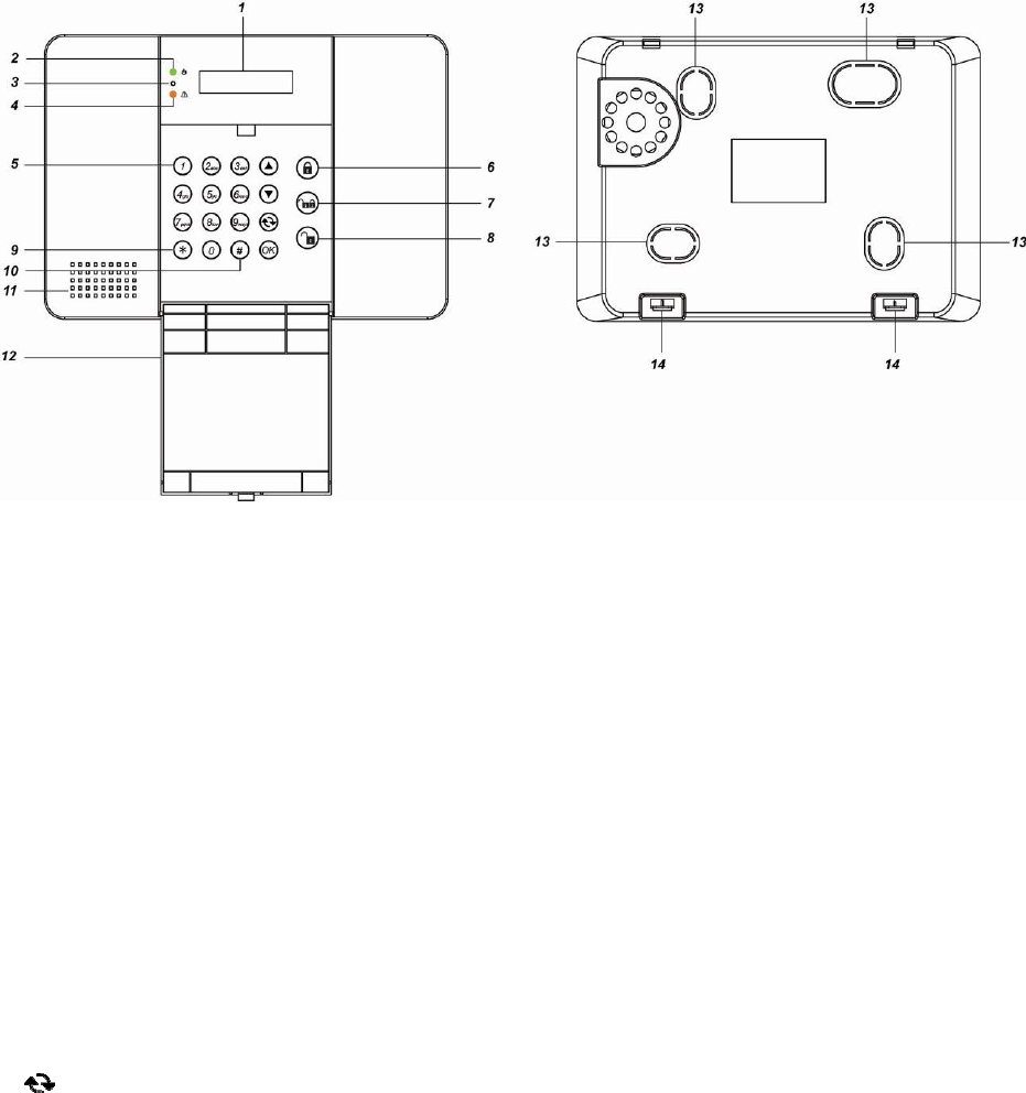
1.1. Parts Identification
Front View Back View (With Back Cover)
1. Backlit LCD Display
2. Power LED (Green)
ON: AC Power on.
OFF: AC Power failure.
3. Microphone
4. Fault LED (Amber)
ON: Fault exists in system
OFF: System Normal
5. Keypad:
Key: Use this key to move the cursor
and scroll the display upwards
Key: Use this key to move the cursor
and scroll the display
downwards
Key: Use this key to abort current
screen and return to previous
screen.
OK Key: Use this key to confirm an action
or entered data
6. Away Arm Key: Use this key to Away
Arm the system.
7. Home Arm Key: Use this key to Home
Arm the system.
8. Disarm Key: Use this key to Disarm the
system.
9. Key: Press and hold for 3 seconds to
enter Installer Menu
10. # Key: Press and hold for 3 seconds to
enter Programming Menu
11. Buzzer
12. Flip Open Keypad Cover: Flip open
the cover to use the Keypad
13. Wall Mounting Knockouts (Inside)
14. Back Cover Latch: Press to open
the latch for removing the back cover
for wiring and switch control
5
1.2. The Power Supply
The Control Panel is powered by a DC12V 2A
AC adaptor which is supplied in the package.
Rechargeable Battery
In addition to the adapter, there is a
rechargeable battery inside the
Control Panel that serves as a back
up powering source in case of any
power failure condition.
During normal operation, the AC
power adapter is used to supply
power to the Control Panel and at the
same time recharge the battery. It
takes approximately 72 hours to fully
charge the battery.
Battery Switch is set as OFF by
factory default, the battery will not be
charged when AC power is connected,
nor will it serve as a back-up power
source when AC power is missing.
You need to switch the battery to ON
after supplying AC power to Control
Panel.
1.3. How to Install the Control
Panel
The easiest way to get to know the system
and get it up and running quickly is to get
all the devices and accessories
programmed on a tabletop before locating
and mounting them.
Step 1. Remove the back cover of your
control panel by pressing the latch
which secures the back cover to the
front cover.
Step 2. The back cover has 4 knockouts
where plastic is thinner for wall
mounting. Break through the
knockouts.
Step 3. Use the knockouts as templates to
mark locations on the wall for wall
mounting, insert wall plugs on
marked location if fixing into plaster
or brick. Screw the back cover onto
the wall.
Step 4. Connect the Ethernet/PSTN cable to
the Control Panel. Also connect the
wired siren, external tamper, and
device for control through the
External Output Terminal is required.
Step 5. Connect the DC12V 2A adaptor to
the panel.
Step 6. Slide Battery Switch to ON position.
Step 7. Break through the side of back cover
for wiring.
Step 8. Hook the Control Panel onto the
back cover on the wall.
Step 9. Plug the adaptor into power socket.
Hardware installation for the Control
Panel is now complete; the Green
Power LED will turn ON.
1.4. Multi-User Passwords
In order to provide maximum security when
operating the system, the Control Panel offers
different levels of authorization for various
situations.
User PIN Code
The User Codes are used for users to
access the alarm system for basic alarm
system function. A total of 10 4-digit User
Codes can be stored in the Control Panel.
Each individual User can be given a
name for easy recognition when viewing
system events. User Names can be
named when first setting them or by
editing them afterwards when resetting
them.
User PIN code #1 is activated with “1234”
as factory default and cannot be deleted.
User PIN code #2~#10 are deactivated
by factory default
Whenever panel asks to key in Enter
Code or, please enter your User PIN
Code.
Master Code
The Master Code has the authorization to
enter Programming Mode for advanced
system setting. When the display panel
asks you to key in M-Code, please enter
your Master Code.
Factory default: 1111

6
Installer Code
The Installer Code is for installer to
program system configurations under
installer menu, such as Tel. Number,
Account Number.
When the display panel asks for I-Code,
please enter your Installer Code.
Factory default: 7982
Guard Code
The Guard Code has the same level of
authorization as the PIN Code. It is
designed for security personnel to access
the alarm system.
Temporary Code
The Temporary Code is designed for the
use of occasional visitors. It has the
same authorization level as the User PIN
Code, but will be removed after one
arming and disarming action.
Duress Code
The Duress Code is specially designed
for situation when the user is under
personal threat. It has the same level of
authorization as User PIN Code, however
when a Duress Code is entered, the
Control Panel will send a silent alarm
report to notify that the user is being
threatened or held against his will.
1.5. System Basic Operation
While entering PIN code, if incorrect
codes have been entered for 5 times.
The keypad input will be prohibited for 10
minute. Any key press during this 10-
minute period will reset the timer to 10
minutes.
When entering information for system
configuration, press key to to leave
current screen, no information will be
saved.
When under user/programming/installer
menu, if no keys are pressed within 2
minutes. the Control Panel will
automatically exit the menu and return to
disarm mode.
If the Control Panel lost power supply.
When the power is restored, it will
resume its previoius mode.
When programming settings, refer to the
following tables to enter symbols and
alphabets, press the key repeatedly until
the desired symbol/alphabet appears.
1.6. Getting Started
After installing the Control Panel and supplying
power, the panel will emit 2 short beep, the
LCD screen will light up and display “Ready to
Arm” with date/time information to indicate the
system is now is Disarm mode (Factory Default)
Ready t o A rm
0 0 : 0 1 J a n 0 1
1 1 , ! ? - 【 】 @ /
2 2 A B C a b c
3 3 D E F d e f
4 4 G H I g h i
5 5 J K L j k l
6 6 M N O m n o
7 7 P Q R S p q r s
8 8 T U V t u v
9 9 W X Y Z w x y z
0 0 <space> / - & ’ . +︰
Delete character and backspace

7
2. System Configuration
In order to configure the Control Panel setting,
you need to enter the Installer Menu. To enter
the Installer Menu:
Step 1. Under Disarm mode:
For touch keypad panel, press any key
to activate the keypad. Keypad
backlight will light up.
Step 2. Press and hold the key on the
numeric keypad for 3 seconds.
You will be prompted a PIN code.
Enter the PIN Code (default user 1 PIN
code: 1234)
E n t e r C o d e
. .. .
Step 3. The following is displayed and you are
prompted to enter the Installer code
(default 7982).
E n t e r I - C o d e
. .. .
Step 4. You will enter the Installer Menu.
W
a l k T e s t
I n s t a l l C o d e
R p t . S e t t i n g
T e s t R e p o r t
T e s t S i r e n
R e c o r d M s g
P l a y Ms g
P a n e l S e t t i n g
G e n . S e t t i n g
D e v i c e + / -
N e t w o r k S e t t i n g
M e d i a U p l o a d
H o me . A u t o .
2.1. Walk Test
The Walk Test function allows you to test
learned in devices. (Please refer to 2.7 Device
+/- for device learning detail)
Step 1. Select Walk Test and press OK to
confirm. You will enter Walk Test
mode..
W
a l k T e s t
Step 2. Press the learn/test button on your
device to transmit a test code (please
refer to device manual for detail). If the
Control Panel receives the test code, it
will display the device information
accordingly. A signal strength RSSI
number will also be displayed on the
top right corner of the LCD screen. The
RSSI scale is 0-9, the greater the
number, the better the signal strength.
2.2. Install Code
This function is for you to edit the Installer code
Step 1. Select Install Code and press OK to
confirm.
E n t e r n e w c o d e
Step 2. Enter the new 4-digit Installer code
and press OK to confirm..
2.3. Report Setting
The Report Setting function allows you to
configure your report destinations. 8 reporting
detinations are available for configuration.
Step 1. Select Rptn. Setting and press OK to
confirm.
1)
2)
..
8)
Step 2. Select the reporting number you want
to program and press OK to confirm.
Step 3. Select the report type
IP(SI A )
IP(CI D )
Mail
Voice
PSTN
Delet e
IP: IP/RF reporting in format.
Mail: email reporting
Voice: Voice message reporting.
PSTN: Digital reporting in format
through PSTN.
Delete: Choose “Delete” to remove
existing report setting.
Step 4. For IP/ PSTN setting, you will be asked
to enter an account number.
Step 5. Enter the IP address for IP reporting,
telephone/mobile number for
Voice/PSTN/Voice reporting, or email
address for email reporting
Step 6. For IP reporting, enter the port number.

8
Step 7. Select a group for the report
destination.
The reporting priority is based on to
group number sequence. From Group
1 Group Group 2 Group 3
….etc
When more than one reporting
destinations are assigned to a group,
if a report is sent to one of the
detinations successfully, the system
will stop reporting to the rest of the
reporting destination in the same
group and move on to report to the
next group.
If the Control Panel fails to send report
to the first detination in a group, it will
move on to the next reporting
destination. If all reporting destinations
in the group cannot be reached, the
Control Panel will move on to the next
group
If the Control Panel fails to report to all
reporting groups, it will start reporting
from group 1 and continue retrying
until one report is made successfully.
<
<N
NO
OT
TE
E>
>
For Voice reporting, the call recipient
must press either the number “1” or
the number “9” button to indicate a
successful Voice report.
Step 8. Select the event type to be reported to
this report destination.
All: All events will be reported.
Status: Only status events will be
reported.
Alarm: Only alarm events will be
reported.
2.4. Test Report
This function is for you to test the reporting
destination you entered.
Step 1. Select Test Report and press OK to
confirm.
Step 2. The Control Panel will send a test
report to the first reporting destination.
2.5. Test Siren
Use the function to test both Control Panel’s
built-in siren and any external siren/bellbox
learnt into the Control Panel function
Step 1. Select Test Siren and press OK to
confirm.
O K t o S t a r t
W
a r n i n g : L o u d !
Step 2. Press OK to confirm. both Control
Panel’s built-in siren and any external
siren/bellbox learnt in the panel will be
activated.
Pr ess O K t o St op
Step 3. Press OK again to stop the siren.
2.6. Record Message
Use the function to record your Address
Message for Voice Report, the Address
Message is the first message played in every
voice report to notify the call recipient of the
caller’s information. The maximum length of
the message is 10 seconds.
Step 1. Select Record Msg and press OK to
confirm.
S t a r t R e c o r d i n g
(O K ? )
Step 2. Press OK to start recording.
R e c o r d i n g . . .
Pr ess O K t o st op
Step 3. The Control Panel will emit a beep.
Start recording after the beep, speak
clearly and slowly for the Control Panel
to record your address. When you
finish recording, press “OK” to stop
recording, the recording will
automatically stop when it reaches 10
second.
<
<N
NO
OT
TE
E>
>
The system will play default alarm
message of “Alarm System” if no
report message is recorded.
2.7. Play Message
Use the function to play your current Address
Message.
Step 1. Select Play Msg and press OK to
confirm.
Step 2. The Control Panel will begin to play
current Address Message once.
P l a y i n g . . .

9
P r e s s O K t o s t o p
2.8. Panel Setting
The Panel Setting menu allows you to program
Control Panel configurations.
Step 1. Select Panel Setting and press OK to
confirm.
K e y w o r d
P - w o r d
A C F a i l R e p o r t
J a mmi n g r e p o r t
A u t o c h e c k - i n
O f f s e t p e r i o d
F o l l o w - o n
T w o - w a y T i me
H a n d s f r e e
R e mo t e A c c e s s
C a l l b a c k T i me r
E x t e r n a l T a mp e r
H i g h T e mp R p t .
L o w T e mp R p t .
B y p a s s F a u l t
Q u i c k K e y
D a t e & T i me
Keyword
The Keyword is used for receiving RF
commands from users. When a user sends a
RF command to the Control Panel through
Vesta EZ Home mobile application, the correct
keyword must be entered along with a valid
User PIN code for the Control Panel to
recognize the command. The Keyword is
disabled by default.
Step 1. Select Keyword and press OK to
confirm.
K e y w o r d
Step 2. The screen will display current
Keyword. Enter the new keyword if you
want to edit keyword, press OK to
confirm the change.
P-word
The P-word is also used for receiving RF
commands from Installers. When an installer
sends a RF command to the Control Panel, the
correct P-word must be entered along with the
Installer code for the Control Panel to
recognize the command. The P-word is
“PROG" by default.
Step 1. Select P-word and press OK to
confirm.
P-
W
o r d
PROG
Step 2. The screen will display current P-word.
Enter the new keyword if you want to
edit keyword, press OK to confirm.
AC Fail Report
This is for you to set the waiting time for the
Control Panel to make report after detecting
AC failure. Factory default is set to 5 minutes.
Step 1. Select AC Fail Report and press OK
to confirm.
Disabl e
1 min
2 min
3 min
4 min
5 min
Step 2. The screen will display current AC fail
report setting. To change the setting,
select a new option and press OK to
confirm.
Jamming Report
This is for you to set whether the Control Panel
to report a detected radio frequency
interference. When set to On, the Control
Panel will report the event whenever jamming
is detected. Factory default is turned Off.
Step 1. Select Jamming report and press OK
to confirm.
Off
On
Step 2. Select to turn on/off the Jamming
report function and press OK to
confirm.
Auto check-in
This is for you to set the interval time the
Control Panel waits before making a regular
check-in report to the programmed reporting
destination. Factory Default is set to 12 hours.
Step 1. Select Auto check-in and press OK to
confirm.
Disab l e
4 hr
8 hr
12 hr
16 hr
20 hr
24 hr
Step 2. The screen will display current Auto
check-in setting. To change the setting,

10
select a new option and press OK to
confirm.
Offset Period
This is to set the time delay before the first
Auto check-in report is made whenever the
Control Panel was powered off, then on again,
or when Auto check-in interval time is changed..
Factory Default is set to 1 hour.
Step 1. Select Offset period and press OK to
confirm.
1 h r
2 h r
. . .
. . .
1 1 h r
1 2 h r
Step 2. The screen will display current Offset
period setting. To change the setting,
select a new option and press OK to
confirm.
Follow-on
Select between Enable or Disable the Follow-
on function. When enabled, After the Control
Panel makes a RF or PSTN digital report to the
Central Monitoring Station, the Central
Monitoring Station will be able to open a two-
way communication channel with the Control
Panel for further assistance.
Step 1. Select Follow-on and press OK to
confirm.
D i s a b l e
E n a b l e
Step 2. The screen will display the settings
available: Enable or Disable. Select one of the
options and press OK to confirm.
Two-way Timer
Set the duration of two-way communication
channel opened by Follow-on, Callback or
Hansfree calls with Two-way Timer function.
Step 1. Select Two-way Time and press OK to
confirm.
1 mi n
3 mi n
5 mi n
N o L i mi t
Step 2. The screen will display current Two-
way setting. To change the setting,
select a new option and press OK to
confirm.
Handsfree
You can Enable or Disable to handsfree
telephone calling function on this panel.
Step 1. Select Hand free and press OK to
confirm.
Disabl e
Enable
Step 2. The screen will display the settings
available: Enable or Disable. Select one of the
options and press OK to confirm.
Remote Access
Configure the Remote Access via RF/PSTN
function. For detail information about Remote
Access, please refer to 4.15. Remote Access.
Disable: Remote access function is disabled
1~15 Rings: The panel will answer incoming
call after selected ring number.
2nd Call: The panel will answer incoming call
after the caller hang up the first call and dial
again within 10~30 seconds.
Step 1. Select Remote Access and press OK
to confirm.
Disabl e
1 Ring
. ...
.....
15 Rin g s
2nd Ca l l
Step 2. The screen will display the settings
available. Select one of the options and press
OK to confirm.
Callback Timer
After the Control Panel makes a report, the
Control Panel will start counting down the
Callback Timer. During the Callback Timer, the
Control Panel will pick up any incoming
telephone call and establish Two-way
communication. After the Callback timer
expires, the Control Panel will no longer pick
up any incoming calls. To configure the
“Callback Timer”:
Step 1. Select Callback Timer and press OK
to confirm.
Disabl e
5 min
10 min
Step 2. The screen will display the options
available: Disable, 5 min, 10 min. Select one
of the options and press OK to confirm setting.

11
External Tamper
This is for you to enable/disable the external
tamper function. Factory default is set to
Disable.
Step 1. Select External Tamper and press OK
to confirm.
D i s a b l e
E n a b l e
Step 2. Select to disable/enable the External
Tamper and press OK to confirm.
High Temperature Alarm
This is for you to set the High Temperature
reporting threshold. If the Control Panel has
learnt in a Temperature Sensor, it will make
High Temperature report and raise alarm when
the temperature exceeds the threshold. When
the temperature drops 1℃ below set value
again, the Control Panel will send a High
Temperature Restore report. Factory default is
set to Disable.
Step 1. Select High Temp Rpt. and press OK
to confirm.
D i s a b l e
- 1 0 ° C
0 ° C
. . .
. . .
5 0 ° C
Step 2. The screen will display current High
Temperature alarm setting. To change
the setting, select a new option and
press OK to confirm.
Low Temperature Alarm
This is for you to set the Low Temperature
reporting threshold. If the Control Panel has
learnt in a Temperature Sensor, it will make
Low Temperature report and raise alarm when
the temperature drops 1℃ below the threshold.
When the temperature rises above set value
again, the Control Panel will a send Low
Temperature Restore report. Factory default is
set to Disable.
Step 1. Select Low Temp Rpt. and press OK.
D i s a b l e
- 1 0 ° C
0 ° C
. . .
5 0 ° C
Step 2. The screen will display current Low
Temperature alarm setting. To change
the setting, select a new option and
press OK to confirm.
Bypass Fault
This is for you to set whether you want to
ignore fault events regarding Ethernet or
RFfunction. Bypassed fault events will not
displayed or cause the fault LED will to light up
and emit beeps.
Step 1. Select External Tamper and press OK
to confirm.
Disabl e
IP
Step 2. Select either disable/IP/RF and press
OK to confirm.
Quick Key
This is for you to set whether to turn on/off the
Quick Key arming feature with the panel’s
keypad. When turned on, you can arm the
control panel with a simple press of Away Arm
or Home Arm key on the keypad without
entering User PIN Code. If turned off, you can
only arm the panel by entering User Pin Code
first. For detail information about Quick Key
arming, please refer to 4.3. Away Arm Mode
and 4.4. Home Arm 1/2/3 Mode..
Factory default is set to On.
Step 1. Select Quick Key and press OK to
confirm.
Off
On
Step 2. Select to turn on or off the function and
press OK to confirm.
Date & Time
This is for you to set time zone, date and time.
Step 1. Select Date & Time and press OK to
confirm.
T i me Z o n e
Date & T i me
Step 2. The screen will display current time
zone and date/time setting. To change
the time zone, select Time Zone and
press OK.
UTC
L o s A n g e l e s
Denver
Chicag o
New Yo r k
Moncto n
London
Paris
Istanb u l
Moscow

12
T a i p e i
T o k y o
S y d n e y
A u c k l a n d
Step 3. The screen will display current time
zone setting, To change the setting,
select a new option and press OK to
confirm.
Step 4. Select Date & Time to edit Control
Panel date and time.
D a t e & T i me
2 0 1 3 / 0 3 / 2 2 / 0 9 : 1 1
Step 5. The current date and time will be
displayed, you will begin by editing
year. Press Up or Down button to
change current year, press OK to
continue to edit month/date/hour/
minute.
2.9. General Setting
The General Setting menu allows you to
program Control Panel’s alarm related settings
Step 1. Select Gen. Setting and press OK to
confirm.
F i n a l D o o r
A r m F a u l t T y p e
T a mp e r A l a r m
E n t r y T i me
E x i t T i me
A l a r m L e n g t h
S u p e r v i s i o n
S o u n d S e t t i n g
Final Door
If set to On, when the system is Away Armed
with a Door Contact set to Entry attribute, the
system will automatically arm the system once
the Door Contact is closed even if the entry
delay timer has not expired yet.
If set to Off, When the system is Away Armed
with a Door Contact set to Entry attribute, the
system will only arm the system after the entry
delay timer expires. (Factory Default)
Step 1. Select Final Door and press OK to
confirm.
O f f
O n
Step 2. Select to turn On or Off the Final Door
option.
Arm Fault Type
Confirm: When set to Confirm, If you attempt
to arm when a fault exists within the system,
the arming action will be prohibited, and a
message will be displayed “Fault exists! Please
Confirm!” You need to arm the system again to
confirm your action and arm the system.
(Factory Default)
Direct Arm: When set to Direct Arm, If you
attempt to arm when a fault exists within the
system, the system will enter selected arm
mode without further notification about fault
events.
Step 1. Select Arm Fault Type and press OK
to confirm.
Confi r m
Direc t A r m
Step 2. Select either Confirm or Direct Arm,
and press OK to confirm.
Tamper Alarm
Away Arm: Tamper alarm will only be
activated when tamper switch is triggered
under Away Arm mode (Tamper event will still
be reported normally in Home/Disarm mode).
(Factory Default)
Always: Tamper alarm will be activated
whenever tamper switch is triggered.
Step 1. Select Tamper Alarm and press OK to
confirm.
Away A r m
Alway s
Step 2. Select either Away Arm or Always, and
press OK to confirm.
Entry Time
If a device set to Entry attribute is triggered
when the system is armed, the Control Panel
will begin an Entry Delay countdown timer
according to your Entry Time setting. The
system must be disarmed before the timer
expires or an alarm will be activated. The Entry
Timer for Away Arm/Home Arm 1/Home Arm 2/
Home Arm 3 can be programmed separately.
(Factory Default is 10 seconds)
Step 1. Select Entry Time and press OK to
confirm.
Away A r m
H o me A r m 1
H o me A r m 2
H o me A r m 3
Step 2. Select an arm mode to edit its Entry
Time, press OK to confirm.
Disabl e
10 sec

13
. . .
. . .
7 0 s e c
Step 3. The screen will display current setting.
To change the setting, select a new
option and press OK to confirm.
Exit Time
When you arm the system, the Control Panel
will begin an Exit Delay countdown timer
according to your Exit Time setting, and enter
selected arm mode after the timer expires.
(Factory Default is 10 seconds)
Step 1. Select Exit Time and press OK to
confirm.
A w a y A r m
H o me A r m 1
H o me A r m 2
H o me A r m 3
Step 2. Select an arm mode to edit its Exit
Time, press OK to confirm.
D i s a b l e
1 0 s e c
. . .
. . .
7 0 s e c
Step 3. The screen will display current setting.
To change the setting, select a new
option and press OK to confirm..
Alarm Length
When an alarm is activated, both the Control
Panel siren and external siren will raise alarm
according to the Alarm Length setting. (Factory
Default is 3 minutes.)
Step 1. Select Alarm Length and press OK to
confirm.
D i s a b l e
1 mi n
. . .
. . .
1 5 mi n
Step 2. The screen will display current setting.
To change the setting, select a new
option and press OK to confirm.
Supervision
Set the supervision timer for accessory devices,
if no supervision signal is received within set
duration for a certain device, the Control Panel
will report the situation accordingly. (Factory
Default is 12 hour)
Step 1. Select Supervision and press OK to
confirm.
Disabl e
4 hr
6 hr
...
...
1 day
Step 2. Select your desired Supervision time,
press OK to confirm.
Sound Setting
This function allows you to program various
sound
Step 1. Select Sound Setting and press OK to
confirm.
Door C h i me
Entry A r m
Entry H o me
Exit A r m
Exit H o me
W
a r n i n g B e e p
Step 2. Select the function you want to edit
and press OK to confirm. Available
options include:
Off
Low
Medium
High
Door Chime: If not turned off, the
Control Panel will sound a door chime
sound when a Door Contact set to
Entry attribute is activated in Disarm
mode.
Entry Arm: If not turned off, the
Control Panel will sound beeping
sounds when a Door Contact set to
Entry attribute is activated in Away
Arm mode.
Entry Home: If not turned off, the
Control Panel will sound beeping
sounds when a Door Contact set to
Entry attribute is activated in Home
Arm mode.
Exit Arm: If not turned off, the Control
Panel will sound beeping sounds
when during Exit Delay Timer for
Away Arm mode.
Exit Home: If not turned off, the
Control Panel will sound beeping
sounds when during Exit Delay Timer
for Away Arm mode.
Warning Beep: If not turned off, the

14
Control Panel will sound beeping
sounds every 30 seconds when fault
exists within system.
2.10. Device +/-
Devices +/- menu allows you to
add/change/delete all available devices. A total
of 40 devices can be included in the Control
Panel.
Step 1. Select Device +/- and press OK to
confirm.
A d d D e v i c e
E d i t D e v i c e
R e mo v e D e v i c e
P r o g r a m S i r e n
G r o u p C o n t r o l
Add Device
Use this function in include new device into the
Control Panel. A maximum of 40 devices can
be learnt into the Control Panel.
Step 1. Select Add device +/- and press OK
to confirm.
P u s h B u t t o n O n
D e v i c e t o A d d
Step 2. Press the learn button on the device
you want to learn in to transmit a learn
code, please refer to the device
manual for detail.
Step 3. If the learning code is received
successfully by the Control Panel, the
device information will be displayed on
the LCD screen. Press OK to add the
device into Control Panel.
D e t e c t e d ( O k ? )
D o o r C o n t a c t
Step 4. Repeat Step 1~3 to learn in other
devices.
Edit Device
Use this function edit the devices learnt into the
Control Panel in Add Device.
Step 1. Select Edit device +/- and press OK to
confirm.
Step 2. Devices that have already been learnt
in will be displayed along with their
zone number (Z01, Z02…etc).
D C Z 0 1
I R Z 0 2
<
<N
NO
OT
TE
E>
>
The available of devices are listed as
followings:
Door Contact --- DC
PIR Sensor --- IR
Pet Immune PIR Sensor--IRP
External PIR - -EIR
Remote Controller --- RC
Carbon Monoxide --- CO
Smoke Detector --- SD
Water Sensor --- WS
Panic Button --- PB
Night Switch --- NS
Remote Keypad --- KP
Indoor Siren --- SR
Outdoor Bellbox --- BX
Power Switch --- PSS
Power Swich Meter --- PSM
PIR Camera --- 852
PIR Video Camera --- 873
Step 3. Step the device you want to edit, press
OK to confirm.
Burgla r
Home O mi t
Home1/ 2 O mi t
Home1/ 3 O mi t
H o me A c c e s s
D e l a y Z o n e
Away O n l y
Entry
Away E n t r y
24 HR
Fire
M e d i c a l / E mg .
W
ater
Set/Un s e t
S i l e n t P a n i c
P e r s o n a l A t t .
Step 4. You will enter attribute setting page for
the device. The device attribute
determines this device’s behavior,
please refer to attribute list below to
select an attribute, Factory Default is
set to Entry for Door Contact and
Away Only for PIR Sensor
Burglar

15
When the system is in any Arm
mode, if a “Burglar” device is
triggered, a “Burglar Alarm” will
be activated immediately and
reported.
Home Omit
When the system is in Home
Arm 1/2/3 mode, if a “Home
Omit” device is triggered, the
Control Panel will not raise
alarm. It will still send a report
for this event
When the system is in Full Arm
mode, if a “Home Omit” device
is triggered, the Control Panel
will respond in the same way as
if a “Burglar” device is triggered.
Home 1/2 Omit
When the system is in Home
Arm 1/2 mode, if a “Home 1/2
Omit” device is triggered, the
Control Panel will not respond. It
will still send a report for this
event
When the system is in Away
Arm or Home Arm 3 mode, if a
“Home 1/2 Omit” device is
triggered, the Control Panel will
respond in the same way as if a
“Burglar” device is triggered.
Home 1/3 Omit
When the system is in Home
Arm 1/3 mode, if a “Home 1/3
Omit” device is triggered, the
Control Panel will not respond. It
will still send a report for this
event
When the system is in Away
Arm or Home Arm 2 mode, if a
“Home 1/2 Omit” device is
triggered, the Control Panel will
respond in the same way as if a
“Burglar” device is triggered.
Home Access
When the system is in Home
mode, if a “Home Access”
device is triggered, the Control
Panel will start an Entry Delay
period to give enough time to
disarm the system. It will also
send a report for this event
When the system is in Full Arm
mode, if a “Home Access”
device is triggered, the Control
Panel will start a Burglar Alarm
and a burglar message will be
reported.
Delay Zone
When the system is in any Arm
mode, if a “Delay Zone” device
is triggered, a “Burglar Alarm”
will be activated immediately
and reported.
When the system is in any
Armed mode, and the Control
Panel is counting down the
Entry Delay, if a “Burglar”
device is triggered, the Control
Panel will not respond.
During the Exit Delay period, if a
“Burglar” device is triggered,
the Control Panel will not
respond .
Away Only
When the system is in Away
Arm mode, if an “Away Only”
device is triggered, a “Burglar
Alarm” will be activated
immediately and reported.
When the system is in any
Home Arm mode, if an “Away
Only” device is triggered, the
Control Panel will not respond.
During the Entry Delay or Exit
Delay period, if an “Away Only”
device is triggered, the Control
Panel will not respond .
Entry
When the system is in any Arm
mode, if an “Entry” device is
triggered, the Control Panel will
start an Entry Delay countdown
timer for the user to disarm the
system.
After the delay period has
expired and no correct PIN code
has been entered, the Control
Panel will activate its built-in
siren immediately to remind the
user the delay period has
expired.
If the Control Panel is not
disarmed within 30 seconds

16
after the delay period expires, a
Burglar Alarm will be reported
and the external sirens included
in the Control Panel will also be
activated. Disarming the Control
Panel within the 30 second
period will return the system to
Disarm mode and silence the
built-in siren. No alarm event will
be reported.
When the system is in Disarm
mode, the Control Panel will
make a “ding-dong” Door
Chime sound on “Entry” (if Door
Chime function is not disabled).
Away Entry
When the system is in Away
Arm, if an “Away Entry” device
is triggered, the Control Panel
will start an Entry Delay
countdown timer for the user to
disarm the system.
After the delay period has
expired and no correct PIN code
has been entered, the Control
Panel will activate its built-in
siren immediately to remind the
user the delay period has
expired.
If the Control Panel is not
disarmed within 30 seconds
after the delay period expires, a
Burglar Alarm will be reported
and the external sirens included
in the Control Panel will also be
activated. Disarming the Control
Panel within the 30 second
period will return the system to
Disarm mode and silence the
built-in siren. No alarm event will
be reported.
When the system is in Disarm
mode, if a “Entry” is triggered,
the Control Panel will make a
“ding-dong” sound (if Door
Chime function is not disabled).
When the system is in any
Home Arm mode, if an “Away
Entry” device is triggered, the
Control Panel will not respond.
During the Entry Delay or Exit
Delay period, if an Away Entry
device is triggered, the Control
Panel will not respond
24 Hour
The 24 Hour device is active all
the time and does not have to
be armed or disarmed. An Event
Code of #130 will be reported
with trigger.
Fire
The Fire device is active all the
time and does not have to be
armed or disarmed. An Event
Code of #111 will be reported
with trigger.
Medical Emergency
A Medical Emergency device
is active all the time and does
not have to be armed or
disarmed. An Event Code of
#101 will be reported with trigger.
Water
The Water device is active all
the time and does not have to
be armed or disarmed. An
Event Code of #154 will be
reported with trigger.
Set/Unset (For Door Contact Only)
If the Door Contact is set to
Set/Unset, the system will be
disarmed when the Door
Contract is triggered, and armed
when Door Contact is closed.
Silent Panic
If the device attribute is set as
Silent Panic, when the device
is activated, the Control Panel
will report a Slient Panic alarm
without sounding an audible
siren. An event code of 122 will
be reported.
Personal Attack
If the device attribute is set as
Personal Attack, when the
device is activated, the Control
Panel will activate an alarm and
report an event code of 120 will

17
be reported.
Step 5. Select if you want to permanently
bypass the device. Permanently
Bypass will deactivated selected
device until you unselect the function.
The Control Panel will ignore all signal
sent from Permanently Bypassed
device, include Low Battery and
Tamper signal. Press OK to confirm.
Factory Default is Normal.
N o r ma l
P e r ma n . B y p a s s
Step 6. Select to on or off latch report. When
turned on, the Control Panel will send
a report if the device is triggered.
Press OK to confirm.
L a t c h R p t O f f
L a t c h R p t O n
For Power Switches, you will be
required to assign a group to the
Power Switch instead
G r o u p 1
G r o u p 2
. . .
G r o u p 8
Step 7. Select a name for the device among
the default device name list and press
OK to confirm. If you want to enter
device name manually, select “User
Define.” (If you have edited the device
name previously, “User Define” will be
replaced with the name previously
entered)
U s e r D e f i n e
A t t i c
B a c k d o o r
B a l c o n y
B a s e me n t
B e d r o o m
C l o s e t
C o r r i d o r
D i n n i n g r o o m
D r i v e wa y
E n t r a n c e
E q u i p me n t
E x i t
F i r s t F l o o r
U p p e r f l o o r
F r o n t d o o r
G a r a g e
G a r d e n
G u e s t R o o m
H a l l
K i t c h e n
Laundr y
Librar y
L i v i n g r o o m
Lobby
Main D o o r
Pantry
Patio
Recept i o n
Roof
Side
Stair
Storag e
Toilet
Yard
Step 8. The name you selected will be
displayed, edit the name if required
then press OK to confirm
Edit n a me
Remove Device
Use this function remove a leant in device.
Step 1. Select Remove Device +/- and press
OK to confirm.
Step 2. The screen will display learnt in device
list. Select the device you want to
remove, press OK to confirm.
Program Siren
The program siren functions allows you to
learn in siren/bellbox and program their
behaviour.
L e a r n S i r e n
S i r e n T a mp . O n
S i r e n T a mp . O f f
Confir m O n
Confir m O f f
E n t r y S n d . O n
E n t r y S n d . O f f
Learn Siren: Follow steps below to
learn in siren to the alarm system:
Step 1. Put the siren into learning mode,
please refer to the Siren manual for
detail.
Step 2. Select Learn Siren, press OK to
confirm.
Step 3. The Control Panel will transmit learning
code to the siren. If the siren receives
the learn code, it will react accordingly,
please refer to your siren manual for
detail.
<
<N
NO
OT
TE
E>
>

18
For SR-15 or BX-15, please learn in
the siren according to the instruction
in Add Device.
Siren Tamper On/Off
Siren Tamp.On: When selected, the Siren’s
tamper protection will be enabled.
Siren Tamp.Off: When selected, the Siren’s
tamper protection will be disabled.
Confirm On/Off
Confirm On: When selected, the Siren will
emit beeping sound when the system is armed
or disarmed.
Confirm Off: When selected, the Siren will not
emit beeping sound when the system is armed
or disarmed.
Entry Sound On/Off
Entry Snd.On: When selected, the Siren will
emit beeping sound during Entry Delay
countdown timer
Entry Snd.Off: When selected, the Siren will
not emit beeping sound during Entry Delay
Countdown Timer
Group Control
The Group Control functions allows you to
control learnt in Power Switch groups.
Step 1. Select Group Control and press OK
to confirm.
Step 2. Select the Power Switch group you
want to control
Step 2. Select to turn on/off the group. All
Power Switches assigned to the group
will be turned on/off accordingly.
2.11. Network Setting
Program your network and email SMTP setting
under this menu.
Step 1. Select Network Setting, press OK to
confirm
C u r r e n t I P
D H C P
I P A d d r e s s
S u b n e t M a s k
G a t e w a y
D N S
S N T P
I n t e r v a l
S M T P
F r o m
Current IP
The Control Panel’s current local area network
IP will be displayed
DHCP
On: If DHCP is set to On, the Network will
obtain the IP address automatically with a valid
Network DHCP Server. You do not need to do
any settings. You can only set DHCP to On if
your Network environment supports DHCP. It
will automatically generate all network
information.
Off: If DHCP is set to Off, you need to enter
the Network information manually for IP
Address, Subnet mask, Gateway, and DNS.
Please make sure that you have obtained all
required values for your Network environment.
Contact local service provider if necessary
IP Address/Subnet Mask/Gateway/DNS
You only need to configure these settings if
DHCP is set to Off.
Step 1. To edit the setting, select the option to
edit and press OK to confirm..
Step 2. Proceed to enter the setting, press OK
to confirm.
SNTP
The SNTP setting is for you to enter an internet
time server IP to synchronize and update
Control Panel time automatically according to
set interval time. Factory Default is:
pool.ntp.org.
Step 1. To edit the setting, select t SNTP and
press OK to confirm..
Step 2. Proceed to enter the IP Address, press
OK to confirm.
I P A d d r e S s
pool.nt p . o r G
Interval
Set the interval time for SNTP setting to update
Control Panel time.
Step 1. To edit the setting, select t Interval and
press OK to confirm.
Step 2. Select your desired interval time, press
OK to confirm..
SMTP
The SMTP setting is for you to program the
mail server related settings. The email account
you set here would be used to send email
report and email the triggered images/videos
from PIR Camera/Video Camera. For email

19
destination, please refer to Media Upload
section.
Step 1. To edit the email information, select
SMTP and press OK to confirm.
Step 2. Proceed to enter the IP address, press
OK to confirm.
S M T P
The format of SMTP setting is:
smtp://user:password@mail server
User: email account user name. For example,
if your email account is john@yahoo.com,
enter john.
Password: email account password.
Mail Server: Email server domain name.
The default port used by SMTP is Port 25. If
you want to specify other ports, enter the port
number according to format below:
smtp://user:password@mail server:port
<
<N
NO
OT
TE
E>
>
SMTP setting must be entered in all
lowercase letters.
The Control Panel does not support
SMTP encryption method such as
SSL or TLS.
From
This is for you to set the email account used to
send captured picture/video and email report.
This setting should be entered along with
SMTP setting.
Step 1. To edit the email information, select
From and press OK to confirm.
Step 2. Enter the email account according to
SMTP setting. Ex: john@yahoo.com.
E ma i l a c c o u n t
<Note>
From setting must be entered in all
lowercase letters.
2.12. Media Upload
The Media Upload menu allows you to set the
destination for the Control Panel to deliver
captured picture/video from PIR Camera, PIR
Video Camera or IP Camera
Step 1. To edit the setting, select Media
Upload and press OK to confirm.
1)
2)
3)
4)
5)
Prefix
1~5
There are 5 upload destinations available for
you to program.
Step 1. Select one of the upload destination
from 1~5, press ok to confirm.
Step 2. Select to either edit or delete the
setting, press OK to confirm..
Edit
Delete
Step 3. If you choose to edit the setting, enter
an email address, FTP address, or
mobile number for MMS delivery.
Email: In order to sent the
picture/video by email, the SMTP and
From setting must be completed first.
The email upload format is: mailto:
user@example.com
MMS: In order to sent the
picture/video to a mobile number the
MMS setting must be completed first.
The MMS upload format is: mms:
mobile number
FTP: The FTP upload format is:
ftp://user:password@IP address:port/
folder
If you choose to delete the setting, the
current upload setting will be removed
Step 4. If you choose to edit the setting, enter
an email address, FTP address, or
mobile number for MMS delivery.
Prefix
The prefix is the title given to every captured
picture or video for you to identify the file.
Step 1. Select Prefix, press OK to confirm.
Step 2. Select to either edit or delete the
setting, press OK to confirm..
Edit
Delete
Step 3. If you choose to edit the setting, enter
a new title and press OK to confirm.
If you choose to delete the setting, the
current Prefix will be removed

20
2.14. Home Automation
The Home Automation function allows you to
set rules to customize your output terminal and
control the device connected to the terminal
with preset condition.
Step 1. Select Home Auto. and press OK to
confirm.
Step 2. You will enter the rule selection menu.
The Control Panel supports 20 Home
Automation rules which can be
programmed separately.
1 ) E mp t y .
2 ) E mp t y
.
.
.
2 0 ) E mp ty
Step 3. Select a rule number and press OK to
confirm. You will be required to set a
condition for the rule to be activated.
E mp t y
M o d e C h a n g e d
A l a r m
G r e a t e r T e mp .
L o w e r T e mp .
T i me r
I n i t i a l
A n y A l a r m
Step 4. According to the condition selected, set
the detail of the condition and press
OK to confirm.
Mode Change
The rule will be activated when the Control
Panel enters selected mode.
Alarm
The rule will be activated when the selected
alarm is triggered.
Greater Temp.
The rule will be activated when the
temperature rises above set temperature.
Greater Temp. Zone
The rule will be activated when the
temperature of the selected temperature
sensor rises above set temperature..
Lower Temp.
The rule will be activated when the
temperature drops below set temperature.
Lower Temp. Zone
The rule will be activated when the
temperature of the selected temperature
sensor drops below set temperature.
Timer
The rule will be activated according to set time..
Initial.
The rule will be activated when the Control
Panel is powered up.
Any Alarm
The rule will be activated when the any alarm
is triggered
Step 5. Set the action to be executed when the
condition is met and press OK to
confirm.
Empty
S w i t c h O u t p u t
S w i t c h G r o u p
S w i t c h Z o n e
Reqest M e d i a
Step 6. According to the action selected, Set
the detail of the action you want to take.
Switch Output
Select to turn on/off the output terminal and the
duration.
Switch Group
Select the Power Switch Group you want to
turn on/off and the duration.
Switch Zone
Select the single Power Switch zone you want
to turn on/off and the duration.
Request Media
All PIR Camera/PIR Video Camera/IP Camera
learnt in the Control Panel will take a picture/
video.
Apply Scene
The selected scene number will be activated.
For scene setting, please refer to IP Installation
Guide for detail.
3. Programming Menu
The programming menu is designed for user to
mange User PIN codes and other setting. to
enter the Programming Menu:

21
Step 1. Under Disarm mode:
For touch keypad panel, press any key
to activate the keypad. Keypad
backlight will light up
Step 2. Press and hold the # key on the
numeric keypad for 3 seconds.
You will be prompted a PIN code.
Enter the PIN Code (default user 1 PIN
code: 1234)
E n t e r C o d e
. .. .
Step 3. The following is displayed and you are
prompted to enter the Master code
(default 1111).
E n t e r M - C o d e
. .. .
Step 4. You will enter the Programming Menu.
W
a l k T e s t
P i n C o d e
M a s t e r C o d e
T e mp C o d e
D u r e s s C o d e
G e n . S e t t i n g
D e v i c e + / -
3.1. Walk Test
The Walk Test function under Programming
Menu functions the same as the Walk Test
function in Installer Menu. Please refer to 2.1.
Walk Test for detail.
3.2. PIN Code Setting
The User Codes are used for users to acess
the alarm system. A total of 10 4-digit User
Codes can be stored in the Control Panel.
Each individual User can be given a name for
easy recognition User PIN Code #1 is set to
1234 by Factory Default.
Step 1. Select Pin Code, press OK to confirm.
Step 2. You will enter the PIN code menu.
Select the PIN code you want to edit,
then press OK to confirm.
1 )
2 ) . . . .
. . .
. . .
9 ) . . . .
1 0 ) . . . .
Step 3. For an existing PIN code, you will be
asked whether you want to delete the
PIN code (except for PIN code 1 which
cannot be deleted), press OK to
confirm if you want to delete the PIN
code
For an empty PIN code, you will be
prompted to enter a new code.
E n t e r n e w c o d e
. . . .
Step 4. Select a new PIN code and press OK,
you will be asked to repeat the code
again.
R e p e a t n e w c o d e
. . . .
Step 5. Select to turn on/off Latch option.
When set to On, the system will report
all arm/disarm action by this user.
Press OK to confirm.
User N a me
Step 6. Enter a User Name for this PIN Code,
you can also leave this field blank.
Press OK to confirm. The PIN code
setting is now complete.
3.3. Master Code
The Master Code is used to access the
Programming Menu. Factory Default is set to
1111. To change the Master Code.
Step 1. Select Master Code and press OK to
confirm. You will be prompt to enter a
new Master Code.
E n t e r n e w c o d e
. . . .
Step 2. Enter the new code and press OK, you
will be asked to repeat the code again.
R e p e a t n e w c o d e
. . . .
Step 3. Repeat the new code and press OK to
confirm. Master Code setting is now
complete.
3.4. Temporary Code
The Temporary Code is used to access the
system for a temporary user and is valid only
once per arming and once per disarming.
Afterwards, the Temporary Code is
automatically erased and needs to be reset for
a new Temporary user. To set the Temporary
Code.

22
Step 1. Select Temp Code and press OK to
confirm. You will be prompt to enter a
new Temporary Code.
E n t e r n e w c o d e
. .. .
Step 2. Enter the new code and press OK, you
will be asked to repeat the code again.
R e p e a t n e w c O d e
. .. .
Step 3. Repeat the new code and press OK to
confirm. Temporary Code setting is
now complete.
3.5. Duress Code
The Duress Code has the same function as the
User PIN code. It is used to access the system
in duress situation. When this code is used for
accessing the system, the Control Panel will
report a secret alarm message without
sounding the siren to the Central Monitoring
Station to indicate of a “Duress Situation in
Progress”. To set the Duress Code:
Step 1. Select Duress Code and press OK to
confirm. You will be prompt to enter a
new Duress Code.
E n t e r n e w c o d e
. .. .
Step 2. Enter the new code and press OK, you
will be asked to repeat the code again.
R e p e a t n e w c O d e
. .. .
Step 3. Repeat the new code and press OK to
confirm. Duress Code setting is now
complete.
3.6. General Setting
The General Setting function under
Programming Menu functions the same as the
General Setting function in Installer Menu.
Please refer to 2.8. General Setting for detail.
3.7. Device +/-
The Device +/- function under Programming
Menu functions the same as the Device +/-
function in Installer Menu. Please refer to 2.9.
Device +/- for detail.
4. Operation
4.1. LCD Display
The Control Panel’s LCD will display the
system information according to different status
and panel modes.
Disarm mode
When the system is in Disarm mode, and no
fault exists in system, the LCD will display
“Ready to Arm”.
Ready t o A rm
0 0 : 0 1 J a n 0 1
When fault events exists in system, The LCD
will display the fault event on screen, followed
by “(XX)”. The XX represents the number of
fault event in system.
When Control Panel or accessory tamper open
status is detected, the LCD will display
“Tamper Zone”
T a m p e r Z o n e ( X X )
0 0 : 0 1 J a n 0 1
When Door Contact in the system is opened
(not aligned with magnet), the LCD will display
“Open Zone”
O p e n Z o n e ( X X )
0 0 : 0 1 J a n 0 1
When other fault exists in system, the LCD will
display “Fault”
F a u l t ( X X )
0 0 : 0 1 J a n 0 1
Away Arm / Home Arm mode
When the system is in Away Arm or Home Arm
mode, and no fault event exists in system, the
LCD will display current mode.
Awa y A r m
0 0 : 0 1 J a n 0 1
When the system is in Away Arm or Home Arm
mode, and fault event exists in system, the
LCD will display (XX) after current mode. The
XX represents the number of fault event in
system.
Awa y A r m( X X )
0 0 : 0 1 J a n 0 1
View Fault Events

23
When fault event exists in system, press Down
key to view fault events.
Step 1. The screen will display:
S T A R T
Step 2. Press Down key to scroll through the
fault events. When all fault events are
displayed, the screen will show:
E N D
Step 3. Press key to exit fault display.
4.2. Entering User Menu
When the system is in Disarm mode, enter a
valid user code to access the User Menu,
When the first numberic key is pressed, the
display will show:
E n t e r C o d e
.. . .
Enter the 4-digit user PIN code followed by OK,
within 30 sec.
The options are available for user menu:
o F a u l t D i s p l a y
L o g
A l a r m M e mo r y
B y p a s s
A p p l y S c e n e
A w a y A r m
H o m e A r m 1
H o m e A r m 2
H o m e A r m 3
<
<N
NO
OT
TE
E>
>
If you wish to arm the system when
fault event exists, please refer to 4.4.
Force Arm below.
4.3. Away Arm Mode
The Away Arm Mode will arm all divice in the
Control Panel to react accordingly upon alarm
trigger
Entering Away Arm mode
Step 1:
Select Away Arm under User Menu
and press OK.
When under Disarm mode, enter a
User PIN code and press the Away
Arm key on the Control Panel.
When under Disarm mode, enter a
User PIN code and press the Away
Arm key on the Remote Keypad.
(Please refer to Remote Keypad
manual for detail)
Press the Away Arm key on the
Remote Controller
When under Disarm mode, press the
Away Arm key on the Control Panel
for quick arm. (Quick Key arming must
be enabled in Panel Setting)
Use the Control Panel webpage to
Away Arm the Control Panel.
Send an RF command (Please refer
to 5.Vesta EZ Home Application).
Step 2. The Control Panel will begin Exit
Delay Timer countdown according to
the setting. The screen will display:
T i me t o e x i t
X X X s e c
Step 3. When the timer expires, the Control
Panel will enter Away Arm mode and
emit a long beep to indicate.
<
<I
IM
MP
PO
OR
RT
TA
AN
NT
T
N
NO
OT
TE
E>
>
If Final Door is set to ON, when the
Door Contact set to Entry Attribute is
closed. The Control Panel will enter
Away Arm mode even if the Exit Delay
Timer has not expired yet.
4.4. Home Arm 1/2/3 Mode
The Home Arm Mode allows the home to be
Partial Armed, Thus, part of the System is
protected with the Alarm, yet, the other areas
allows the user to move freely without self
triggering the alarm.
The Control Panel has 3 Home Arm Mode from
1 to 3. Devices with their attribute set to Home
Omit or Away Only will not be triggered under
any Home Arm mode. Device set to Home 1/2
Omit will not be triggered under Home Arm 1/2
mode. Device set to Home 1/3 Omit will not be
triggered under Home Arm 1/3 mode.
Entering Home Arm mode
Step 1:
Select Home Arm 1~3 under User
Menu and press OK.

24
When under Disarm mode, enter a
User PIN code and press the Home
Arm key on the Control Panel. (Home
Arm 1 only)
When under Disarm mode, enter a
User PIN code and press the Home
Arm key on the Remote Keypad.
(Home Arm 1 only, please refer to
Remote Keypad manual for detail)
Press the Home Arm key on the
Remote Controller(Home Arm 1 only).
When under Disarm mode, press the
Home Arm key on the Control Panel
for quick arm (Home Arm 1 only,
Quick Key arming must be enabled in
Panel Setting)..
Use the Control Panel webpage to
Home Arm the Control Panel.
Send an RF command (Home Arm 1
only, please refer to 5.Vesta EZ Home
Application).
Step 2. The Control Panel will begin Exit
Delay Timer countdown according to
the setting. The screen will display:
T i me t o e x i t
X X X s e c
Step 3. When the timer expires, the Control
Panel will enter selected Home Arm
mode and emit 3 short beeps.
4.5. Force Arm
When you arm the system, if any fault event
exists in the system, the arming action will be
prohibited and the fault event will be displayed
on screen.
At this moment, you can either rectify all of the
problems and clear the Fault Display. The
Control Panel will be able to be armed normally.
If you want to arm the system without
correcting the fault situation, follow the steps
below to Forced Arm the Control Panel.
Step 1: When fault events are displayed,
repeat the same arming action again
Step 2: The Control Panel will begin Exit Delay
Timer countdown according to the
setting. The screen will display:
T i me t o e x i t
X X X s e c
Step 3. When the timer expires, the Control
Panel will enter selected arm mode
accordingly.
4.6. Disarm
When the system is under Away Arm or Home
Arm mode, to disarm the system:
Step 1:
Enter a User PIN code on the Control
Panel keypad and press Disarm key
or OK key.
Enter a User PIN code on the Remote
Keypad and press Disarm key.
Press the Disarm key on the Remote
Controller.
Use the Control Panel webpage to
disarm the Control Panel.
Send an RF command (Please refer
to 5.Vesta EZ Home Application).
Step 2: The Control Panel will return to Disarm
mode.
4.7. Temporary Bypass
The Bypass function allows you to deactivate a
device temporarily for one arming/disarming
period. When a bypassed sensor (IR/DC/PIR
Camera) is triggered, the panel will ignore the
signal from the sensor and will not raise alarm.
To Bypass a sensor:
Step 1. Select Bypass, press OK to confirm.
The screen will display your device list:
DC Z0 1
IR Z0 2
Step 2. Select the sensor you want to bypass
and press OK. The sensor will be
marked with a + to indicate it is
bypassed. You can also remove the
bypass condition by selecting the
sensor and press OK again.
+DC Z0 1
IR Z0 2
The bypassed condition of a sensor will be
remove automatically after the panel is armed,
then disarmed. For Door Contact, the condition
will also be removed when the Door Contact is
closed.
4.8. Apply Scene

25
You can activate programmed Scene number
under the User Menu. Before applying a scene,
the scene must be programmed first through
the Control Panel webpage. Please refer to the
IP Installation Guide for detail.
To apply a scene:
Step 1. Select Apply Scene, press OK to
confirm. The screen will display scene
numbers from 1~10 along with Scene
name:
1
2
1 0
Step 2. Select the scene you want to activate
and press OK to confirm.
4.9. Dual Key Alarm
You can activate an alarm manually by
pressing buttons on the Control Panel keypad
anytime regardless of system mode.
Panic Alarm
Press and hold 1 and 3 keys together for 3
seconds to trigger a panic alarm.
Fire Alarm
Press and hold 4 and 6 keys together for 3
seconds to trigger a fire alarm.
Medical Emergency Alarm
Press and hold 7 and 9 keys together for 3
seconds to trigger a medical emergency alarm.
Step 1. Press and hold both keys together to
trigger alarm, the screen will prompt
you to enter PIN code when you first
press the keys.
E n t e r C o d e
.. . .
Step 2. Ignore the screen prompt and continue
to hold both keys for 3 seconds. Then
the alarm will be activated
4.10. Alarm Activation
When an alarm is activated because of a
device/event trigger, the LCD screen will
display “ALARM! ALARM!” to notify the user.
During this time, the Control Panel will also
sound the siren, and send out a corresponding
alarm report to the programmed destination(s).
Stopping the Alarm
Step 1: To Stop the alarm, disarm the Control
Panel, please refer to 4.5. Disarm for
detail.
Step 2: The alarm will be stopped, the device
that triggered the alarm will be
displayed on screen. Use the Down
button to scroll down the alarm event,
the screen will display whether the
system reported successfully to
programmed destination or not.
Step 3: When you finished viewing the alarm
event, the Control Panel will enter
Disarm mode.
<
<I
IM
MP
PO
OR
RT
TA
AN
NT
T
N
NO
OT
TE
E>
>
The Remote Controller cannot be
used to stop the panic alarm triggered
by itself.
Stopping the alarm will not stop the
alarm reporting, please refer to 2.3.
Report Setting for more information.
Alarm Memory
You can use the Alarm Memory option to
check previous alarm history.
Step 1: Under the User Manual, select Alarm
Memory and press OK to confirm. If
alarm memory exists in the Control
Panel, the screen will display:
ST A R T
Step 2. Press Down key to scroll through the
alarm events. When all alarm event
are displayed, the screen will show:
E N D
Step 3. You can press Up key to scroll back
through the fault events or press OK
key to exit Alarm Memory.
4.11. Two-Way
Communication
Two-way communication is established during
the following situations:
When the Control Panel makes a
RF/PSTN digital report and CMS open
two-way communication with follow-on
function.
When the Control Panel makes a

26
report and CMS call back within the
Callback Timer.
When the Control Panel makes a
Voice report and the call recipient
presses DTMF “1” key.
When the Control Panel receives an
incoming call during the Calback timer
after making a report.
When an user dials a number using
the Handsfree function of the Control
Panel.
The period of two-way communication is set by
Two-way Timer setting. The Control Panel will
emit a beep 20 seconds and 10 seconds
before the two-way time expires. Pressing the
number “1” will reset the duration to the original
length. Pressing number “9” or “0” ends the
two-way communication.
Handsfree
To initiate handsfree calling:
Step 1. Under disarm mode, press the
button, the following is displayed on the LCD:
H a n d F r e e ( O K ? )
Step 2. Press the OK button to start handsfree
calling. The following is displayed on the LCD.
E n t e r P h o n e N o .
Step 3. Enter the number you wish to dial and
press OK to dial out.
<
<N
NO
OT
TE
E>
>
If an Error message is shown after
pressing the OK button to dial out, it
means the Control Panel is reporting.
Enter the area code of the number as
you would with a mobile phone.
Enter the number as you would with a
landline.
If a Service Telephone number is
programmed through webpage (Refer
to the IP installation guide), the
number will be displayed as default to
allow quick access.
After making a call, the telephone
number will be saved as default for
future calls.
Voice Report & Call Acknowledgement
The Control Panel will dial a number during
voice reporting. When the call recipient picks
up the phone, the Control Panel will delay 5
seconds before starting to play the message.
The Voice message is composed of 3 parts:
1. Address Message: The address message
you recorded. If no Address Message is
recorded, the panel will play message
“Alarm System”.
2. Zone Name: The panel will play the zone
name of the device which triggered the
alarm if the name is selected from the
default zone name list when editing the
device. For alarm triggered by the control
panel, the panel will play message “Control
Panel”.
3. Alarm event: The panel will play the alarm
message according to alarm type which
includes: Burglar, Fire, Medical or
Emergency
To ensure the call is successfully received by
the recipient, the recipient should acknowledge
the message by pressing the appropriate
button on his telephone set.
There are 3 buttons to press during a Voice
reporting:
“1” – Open a two-way communication channel
with the Control Panel. The Control Panel will
acknowledge this report as successful.
“9” – Hang up the call, the Control Panel will
acknowledge the report as successful.
“0” – Hang up the call, the Control Panel will
consider this report as failure and report to the
next destination in the same group.
4.12. Keypad Lockdown
The Control Panel features Keypad Lockdown
function to prevent continuous User PIN Code
retries: If the wrong User PIN Codes are
entered for 5 times within 10 minutes, the
keypad will be locked down for 15 minutes. All
key presses from Control Panel keypad or
Remote Keypads are prohibited during the 15
minute period.
4.13. Tamper Protection

27
The Control Panel is tamper protected from
unauthorized cover opening or removal from
mounted surface after installation by the
Tamper Switch on the back of the Control
Panel. An additional tamper switch can be
connected to the External Tamper Switch
Terminal on the Control Panel. The terminal
will form a Normal Close loop with the tamper
switch and activate when the loop is opened.
When the tamper is triggered:
If the system is in Arm mode:
The Control Panel will always activate a
Tamper Alarm upon tamper switch trigger
and report the alarm event.
If the system is in Home/Disarm mode:
When Tamper Alarm is set to Away Only,
no alarm will be activated when a tamper
switch is triggered under Home/Disarm
mode. A report for tamper trigger will still be
reported.
When Tamper Alarm is set to Always, the
Tamper Alarm will also be activated when a
tamper switch is triggered under
Home/Disarm mode.
For Tamper Alarm setting please refer to 2.7.
General Setting.
Avoiding accidental Tamper alarm when
changing device battery/mounting
location:
Step 1: Use the Bypass function to temporarily
deactivate the device to avoid tamper
trigger.
Step 2: For Indoor Siren or Outdoor Bell Box,
you also need to disabled the Siren
Tamper temporarily.
Step 3: After finish changing battery or
mounting location, remove the Bypass
setting and enable Siren Tamper again
4.14. Fault Display
The Fault Display option is for you to view the
fault events:
Step 1. Select Fault Display, press OK to
confirm. The screen will display:
S T A R T
Step 2. Press Down key to scroll through the
fault events. When all fault events are
displayed, the screen will show:
E N D
Step 3. You can press Up key to scroll back
through the fault events or press OK
key to exit fault display.
<
<N
NO
OT
TE
E>
>
The Control Panel is capable of
detecting following fault events:
Control Panel Low Battery
Control Panel Battery Missing
AC Power Fail
Sensor Out-of-order
Sensor Low Battery
Device and Panel Tamper
Interference Detection
Network and PSTN failure
4.15. Remote Access
The Control Panel features Remote Access
capability for user to control or inquire system
status remotely.
Remote Access in Panel Setting must be set
to 1~15 rings or 2nd call to use this function.
Step 1. Dial the Control Panel’s telephone
number.
If Remote Access in Panel setting is set to
1 ~ 15 rings:
I. Wait for Control Panel to pick up the
call after programmed ring numbers.
II. After the Control Panel picks up the call
it will emit 2 beeps via the handset to
prompt you to enter a User PIN code
If Remote Access in Panel setting is set to
2nd Call:
I. After the Control Panel picks up the call,
hang up the phone.
II. Wait for 10 to 30 seconds then dial the
Control Panel’s telephone number
again.
III. After the Control Panel picks up the call
it will emit 2 beeps via the handset to
prompt you to enter a User PIN code.
Step 2. Enter “User PIN Code + #”. If the PIN
code is correct, the panel will emit 1
beep over the handset to confirm. If
the PIN code is incorrect, the panel will
28
emit 2 beeps to indicate.
Step 3. Enter the following DTMF commands:
1: Disarm the system. The panel will
play voice message to confirm.
2: Home arm the system. The panel
will play voice message to confirm.
3: Away arm the system. The panel will
play voice message to confirm.
9: Hang up.
4.16. Factory Reset
You can clear all programmed settings for the
Control Panel and return all configuration to
factory default by following the below steps
Step 1. Power down Control Panel and turn off
the battery switch.
Step 2. Apply power to the control panel.
Step 3. Press key within 10 seconds after
power on the panel.
Step 4. The Control Panel firmware version will
be displayed.
Step 5. To factory reset the panel, press the
following keys: , then
OK key to confirm
Step 6. Select Factory Reset on the LCD
screen press OK to confirm.
Step 7. Factory Reset is now complete.

29
4.17. Control Panel Mode & Response Table
For Alarm Activation by Events and Control Panel Responses, please refer to the following table:
Control Panel Mode & Response Table
Arm Mode
Alarm Attribute Disarmed
Away Arm Home Arm
1
Home Arm
2
Home Arm
3
Away /
Home Arm
Exit Timer
Away Arm
Entry Timer
Home Arm
Entry Timer
Burglar No Response
Instant
Burglar
Alarm
Instant
Burglar
Alarm
Instant
Burglar
Alarm
Instant
Burglar
Alarm
Instant
Burglar
Alarm
Instant
Burglar
Alarm
Instant
Burglar
Alarm
Home Omit No Response
Instant
Burglar
Alarm
No
Response
No
Response
No
Response
No
Response
Instant
Burglar
Alarm
No
Response
Home1/2 Omit No Response
Instant
Burglar
Alarm
No
Response
No
Response
Instant
Burglar
Alarm
No
Response
Instant
Burglar
Alarm
No
Response
Home1/3 Omit No Response
Instant
Burglar
Alarm
No
Response
Instant
Burglar
Alarm
No
Response
No
Response
Instant
Burglar
Alarm
No
Response
Home Access No Response
Instant
Burglar
Alarm
Start Entry
Timer
Start Entry
Timer
Start Entry
Timer
No
Response
No
Response
No
Response
Away Only No Response
Instant
Burglar
Alarm
No
Response
No
Response
No
Response
No
Response
No
Response
No
Response
Entry
Door Chime
(DC & IR
only)
Start Entry
Timer
Start Entry
Timer
Start Entry
Timer
Start Entry
Timer
No
Response
No
Response
No
Response
Away Entry
Door Chime
(DC & IR
only)
Start Entry
Timer
No
Response
No
Response
No
Response
No
Response
No
Response
No
Response
24 HR Instant Burglar
Alarm
Instant
Burglar
Alarm
Instant
Burglar
Alarm
Instant
Burglar
Alarm
Instant
Burglar
Alarm
Instant
Burglar
Alarm
Instant
Burglar
Alarm
Instant
Burglar
Alarm
Delay Zone No Response
Instant
Burglar
Alarm
Instant
Burglar
Alarm
Instant
Burglar
Alarm
Instant
Burglar
Alarm
No
Response
No
Response
No
Response

30
Fire Instant Fire
Alarm
Instant Fire
Alarm
Instant Fire
Alarm
Instant Fire
Alarm
Instant Fire
Alarm
Instant Fire
Alarm
Instant Fire
Alarm
Instant Fire
Alarm
Medical/Emergency
Instant
Medical
Alarm
Instant
Medical
Alarm
Instant
Medical
Alarm
Instant
Medical
Alarm
Instant
Medical
Alarm
Instant
Medical
Alarm
Instant
Medical
Alarm
Instant
Medical
Alarm
Water Instant Water
Alarm
Instant
Water
Alarm
Instant
Water
Alarm
Instant
Water
Alarm
Instant
Water
Alarm
Instant
Water
Alarm
Instant
Water
Alarm
Instant
Water
Alarm
Set/Unset Arm \ Disarm Arm \
Disarm
Arm \
Disarm
Arm \
Disarm
Arm \
Disarm
Arm \
Disarm
Arm \
Disarm
Arm \
Disarm
Silent Panic Instant Silent
Panic Alarm
Instant
Silent Panic
Alarm
Instant
Silent Panic
Alarm
Instant
Silent Panic
Alarm
Instant
Silent Panic
Alarm
Instant
Silent Panic
Alarm
Instant
Silent Panic
Alarm
Instant
Silent Panic
Alarm
Personal Attack Instant Panic
Alarm
Instant
Panic
Alarm
Instant
Panic Alarm
Instant
Panic Alarm
Instant
Panic Alarm
Instant
Panic Alarm
Instant
Panic Alarm
Instant
Panic Alarm
31
5. Appendix
5.1. Event Code
100 – Medical
101 – Personal emergency
When the Wrist Transmitter /
Emergency Pendant (WTR) is pressed.
102 – Inactive
110 – Fire
111 – Smoke
When the Smoke Detector (SD) is
triggered.
114 – Heat
When the Heat Detector (HD) is
triggered.
120 – Panic
When the Panic Button of the Remote
Controller (RC) is pressed.
121 – Duress
When the Duress Code is entered to
disarm or arm the system.
122 – Silent Panic
When the panic button on a Remote
Controller (RC) set to silent panic is
pressed.
130 – Burglar
When any one of the following devices
is triggered:
The Door Contact (DC) set at
Burglar (@ B)
The Door Contact (DC) set at
Delay (@ D)
The PIR set at Burglar (@ B)
The PIR set at Delay (@ D)
131 – Burglar Perimeter
When a device set as Entry is
triggered in away arm mode.
132 – Burglar Interior
When a device set at Entry is
triggered in home arm mode.
133 – 24 Hours
When a device set as 24 Hour is
triggered.
137 – Panel Tamper
When the Control Panel tamper switch
is triggered.
139 – Verification / Alarm Confirmation
147 – Sensor Supervisor Failure
When the Control Panel fails to
receive the signal transmitted from any
one of the devices individually for a
preset period.
151 – Gas
154 – Water leakage
When a Water Sensor or Door Contact
set as Water is triggered.
158 – High Temperature
When the temperature exceeds High
Temperature setting.
159 – Low Temperature
When the temperature drops below
Low Temperature setting.
162 – CO detector
301 – AC Failure
When the AC power fails for more than
10 sec.
302 – Low Battery
When the battery voltage of the Panel
and any one of the devices is low.
311 – Panel Battery Missing/Dead
When the Control Panel Battery is
missing or disconnected.
344 – Interference
374 – Arm with Fault
When fault exists in system, and the
system is armed by confirming the arm
action. (Arm Fault Type set to Confirm.)
380 – Device AC Failure
When an AC power accessory device
loses the AC power connection.
383 – Device Tamper
When a device’s tamper switch is
triggered.
384 – Device Low Battery
When a device’s is under low battery.
32
389 – Self Test Failure
400 – Arm/Disarm (by Remote Controller)
When the system is armed or
disarmed by using the Remote
Controller.
401 – Arm/Disarm by Panel
When the system is armed or
disarmed by entering the PIN code.
408 – Set/Unset Disarm
407 – Disarm/Away Arm/Home Arm by
Remote Keypad
465 – Alarm Reset
570 – Zone Bypass
When fault exists in system, and the
system is armed by ignoring the fault
event. (Arm Fault Type set to Direct
Arm)
602 – Periodic test report
When Control Panel makes periodic
Check-in reporting.
606 - Follow-On Function
When Control Panel reports to CMS to
request opening Two-way
communication channel.