Climax Technology Co PSM Power Switch User Manual
Climax Technology Co Ltd Power Switch Users Manual
Users Manual
1
PSS-29ZBS(R) / PSM-29ZBS(R) Power Switch Series
Introduction
The Power Switch series include the following models:
PSS-29ZBS: ZigBee Power Switch
PSS-29ZBSR: ZigBee Power Switch with Router function
PSM-29ZBS: ZigBee Power Switch with Meter
PSM-29ZBSR: ZigBee Power Switch with Meter and Router function
The Power Switches are capable of receiving wireless signals from the coordinator in the Zigbee network to
toggle On/Off of appliances that are attached to it.
The Power Switch utilizes ZigBee technology for wireless signal transmission. ZigBee is a wireless
communication protocol that is reliable, has low power consumption and has high transmission efficiency. Based
on the IEEE802.15.4 standard, ZigBee allows a large amount of devices to be included in a network and
coordinated for data exchange and signal transmission.
Models with Meter functions (PSM-29ZBS / PSM-29ZBSR) have the extra feature of keeping tracks of energy
consumption with built-in power meter and transmit the data to coordinator regularly.
Models with router function (PSS-29ZBSR / PSM-29ZBSR) also serve as a router in the ZigBee network. After
being included in the ZigBee network, it allows other ZigBee device to join the network through the Power Switch.
Model No. Meter ZigBee Router
PSS-29ZBS No No
PSS-29ZBSR No Yes
PSM-29ZBS Yes No
PSM-29ZBSR Yes Yes
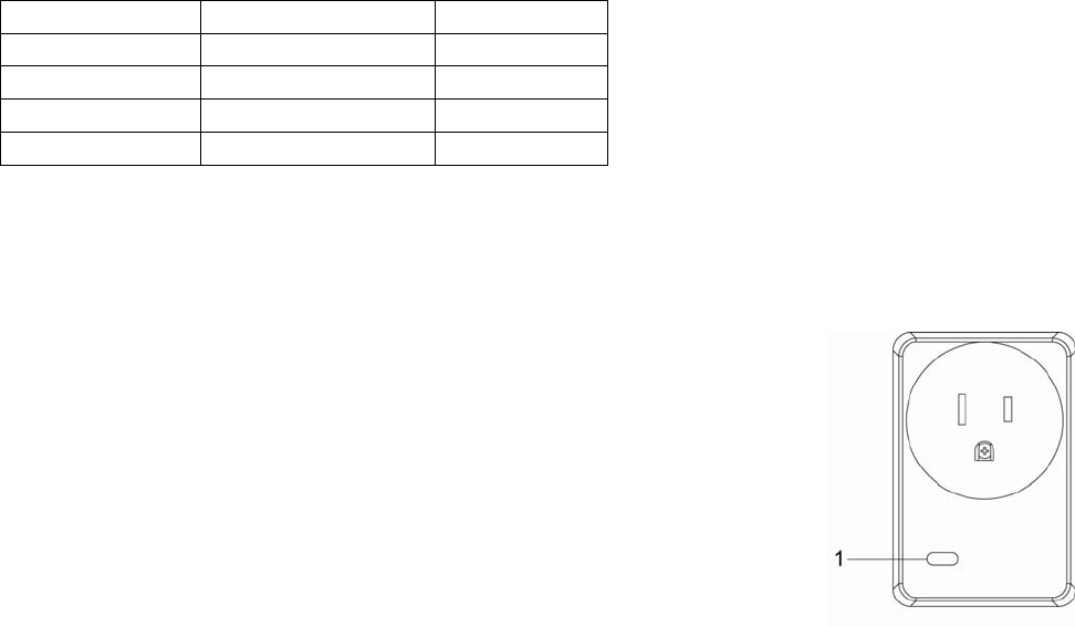
Parts Identification
1. Function Button aka LED indicator
The Function Button also doubles as the LED Indicator. The function button is used to
control the Power Switch. The LED indicator is used to indicate Power Switch status.
LED Indication:
The LED indicator lights up in the following conditions:
- On:
The Power Switch is turned on.
- Off:
The Power Switch is turned off.
- Flashes twice:
The Power Switch has successfully joined a ZigBee network.
- Flashes 5 times
The Power Switch has successfully bound with a controller
- Flashes every 20 minutes
The Power Switch has lost connection to its current ZigBee network
(PSS-29ZBS and PSM-29ZBS only)
Function Button Usage:
- Press the button to toggle on/off the Power Switch
- Press and hold the button for 10 seconds then release to reset the
Power Switch.
- Press and hold the button for 3 seconds then release to bind with a
controller
ZigBee Network Setup
z
z
Z
Zi
ig
gB
Be
ee
e
D
De
ev
vi
ic
ce
e
G
Gu
ui
id
de
el
li
in
ne
e

2
ZigBee is a wireless communication protocol that is reliable, has low power consumption and has high
transmission efficiency. Based on the IEEE802.15.4 standard, ZigBee allows a large amount of devices to
be included in a network and are coordinated for data exchange and signal transmission.
z
z
J
Jo
oi
in
ni
in
ng
g
t
th
he
e
Z
Zi
ig
gB
Be
ee
e
N
Ne
et
tw
wo
or
rk
k
As a ZigBee device, the Power Switch needs to join a ZigBee network to receive commands and transmit
energy consumption information. Follow the steps bellow to join the Power Switch into a ZigBee network.
1. Plug in the Power Switch into a power outlet.
2. Press and hold the function button for 10 seconds as the Power Switch resets and starts searching for
existing ZigBee network. Please make sure the permit-to-join feature on the router or coordinator of your
ZigBee network is enabled.
3. If the Power Switch successfully joins a ZigBee network, the LED Indicator will flash twice to confirm.
4. After joining the ZigBee network, the Power Switch will be registered in the network automatically. Please
check the Zigbee network coordinator, system control panel or CIE (Control and Indicating Equipment) to
confirm if joining and registration is successful.
5. If registration and joining to the network is unsuccessful, please check your ZigBee network coordinator,
system control panel or CIE setting to ensure the permit-to-join function is available, and then use the
Factory Reset function below to join the ZigBee network.
z
z
B
Bi
in
nd
di
in
ng
g
w
wi
it
th
h
C
Co
on
nt
tr
ro
ol
ll
le
er
r
After joining the ZigBee network, the Power Switch can bind itself with a controller device which can be used
to turn on/off the Power Switch. To bind the Power Switch and the device:
1. Press and hold the Function Button for 3 seconds, then release the button. The Power Switch will send
binding request to the coordinator.
2. Refer to your controller manual to send binding request for the device within 16 seconds.
3. If binding is successful, the Power Switch LED indicator will flash 5 times to confirm. You can now use the
controller to adjust power output level for the Power Switch.
4. If binding is unsuccessful, please retry the binding process.
z
z
F
Fa
ac
ct
to
or
ry
y
R
Re
es
se
et
t
If you want to remove the Power Switch from current network and join a new network, you need to use the
Factory Reset function to clear the Power Switch from its stored setting and information first before it can join
another network. To perform Factory Reset:
1. Press and hold the switch button for 10 seconds, release the button until the LED Indicator flash once.
2. The Power Switch has been reset to factory default setting with all its previous network information
removed. It will now actively search for available ZigBee network again and join the network automatically.
3. If the Power Switch successfully joins a ZigBee network, the LED Indicator will flash twice to indicate.
z
z
Z
Zi
ig
gB
Be
ee
e
R
Ro
ou
ut
te
er
r
D
De
ev
vi
ic
ce
e
C
Ca
ap
pa
ac
ci
it
ty
y
(
(P
PS
SS
S-
-2
29
9Z
ZB
BS
SR
R
/
/
P
PS
SM
M-
-2
29
9Z
ZB
BS
SR
R
O
On
nl
ly
y)
)
The Power Switch models with Router function allow other ZigBee devices to join the ZigBee Network
through the Router. The Power Switch Router has maximum capacity of 40 devices/routers; the Power
Switch Meter Router has maximum capacity of 10/routers.
Model No. Maximum ZigBee Device
+ Router Capacity
PSS-29ZBSR 40
PSM-29ZBSR 10
Operation
z
z
I
In
ns
st
ta
al
ll
la
at
ti
io
on
n
z Plug the Power Switch into a power outlet.
z Plug the appliance into the socket of the Power Switch. The appliance must be in ON status.
z IMPORTANT NOTE: The Power Switch does not have a backup battery and will be powered down
when AC power fails. DO NOT use the Power Switch as router for your security sensor or alarm control
devices such as Door Contact, PIR Sensor…etc., otherwise the sensors will lose connection to ZigBee
network if the Power Switch is disconnected from AC power. Plan the installation locations of these
security sensors without using the Power Switch and only use a router with backup battery for them.
The router function of the Power Switch should ONLY be used to provide signal range extension for
other Power Switches/Dimmer.
z
z
A
Ap
pp
pl
li
ia
an
nc
ce
e
C
Co
on
nt
tr
ro
ol
l
z After the Power Switch has successfully joined a ZigBee network, the coordinator can remotely turn
on/off the Power Switch to control the appliance

3
z You can also press the button on the Power Switch to toggle its on/off status
z If you have bound a controller with the Power Switch, you can also use the controller to turn on/off the
Power Switch.
z If the Power Switch is removed from power outlet, after replugging the Power Switch, its previous on/off
status will be restored within 1 minute.
z
z
E
En
ne
er
rg
gy
y
C
Co
on
ns
su
um
mp
pt
ti
io
on
n
M
Mo
on
ni
it
to
or
r
(
(P
PS
SM
M-
-2
29
9Z
ZB
BS
S
/
/
P
PS
SM
M-
-2
29
9Z
ZB
BS
SR
R
O
On
nl
ly
y)
)
z Power Switch models with built-in meter will transmit a signal with its power consumption data every 10
minutes to the ZigBee network coordinator.
z Whenever the Power Switch energy output changes by +/- 2W, it will automatically transmit a signal
with power consumption data to the ZigBee network coordinator for update.
z The Power Switch transmits a signal with power data to coordinator whenever accumulated power
usage increases by 0.1kW/hr.
z If the Power Switch power output is below 20W, the power measurement error may become greater
and the data may be inaccurate.
z To clear the Power Switch of its accumulated power consumption data, follow steps below:
1. Unplug the Power Switch from power outlet.
2. Press and hold the function button and plug in the Power Switch again when holding down the
button.
3. Keep holding the button and release after 3 seconds. The accumulated power consumption data
will be cleared.
z
z
M
Ma
ax
xi
im
mu
um
m
O
Op
pe
er
ra
at
ti
io
on
n
L
Lo
oa
ad
d
z For 120V: the maximum operation load is 15A Resistive or 1/2hp or Tungsten lamp load: 5A
z If the Power Switch is overheating, It will cut off power automatically as a safety measure. The Power
Switch must be unplugged and replugged after cut off to resume normal operation.
Appendix (For developers only)
z
z
C
Cl
lu
us
st
te
er
r
I
ID
D
Device ID: On Off Output :0x0002 / Mains Power Outlet :0x0009
Endpoint:0x0A
Server Side Client Side
Mandatory
Basic (0x0000) None
Identify(0x0003)
Groups(0x0004)
Scenes(0x0005)
On/Off(0x0006)
Optional
Metering(0x0702)(PSM-29ZBS/PSM-29ZBSR Only) None
z
z
A
At
tt
tr
ri
ib
bu
ut
te
e
o
of
f
B
Ba
as
si
ic
c
C
Cl
lu
us
st
te
er
r
I
In
nf
fo
or
rm
ma
at
ti
io
on
n
Identifier Name Type Range Access Default
Mandatory
/ Optional
0x0000 ZCLVersion Unsigned
8-bit integer 0x00 –0xff Read
only 0x01 M
0x0001 ApplicationVersion Unsigned
8-bit integer 0x00 –0xff Read
only 0x00 O
0x0003 HWVersion Unsigned
8-bit integer 0x00 –0xff Read
only 0 O
0x0004 ManufacturerName Character
String 0 – 32
bytes Read
only Climax Technology O
0x0005 ModelIdentifier Character
String 0 – 32
bytes Read
only (Model Version) O
0x0006 DateCode Character
String 0 – 16
bytes Read
only O
0x0007 PowerSource 8-bit 0x00 –0xff Read
only M
0x0010 LocationDescription Character
String 0 – 32
bytes Read /
Write O
0x0011 PhysicalEnvironment 8-bit 0x00 –0xff Read /
Write 0x00 O

4
0x0012 DeviceEnabled Boolean 0x00 –0x0
1 Read /
Write 0x01 M
z
z
A
At
tt
tr
ri
ib
bu
ut
te
e
o
of
f
I
Id
de
en
nt
ti
if
fy
y
C
Cl
lu
us
st
te
er
r
I
In
nf
fo
or
rm
ma
at
ti
io
on
n
Identifier Name Type Range Access Default
Mandatory
/ Optional
0x0000 IdentifyTime Unsigned
16-bit integer 0x00 –0xffff Read /
Write 0x0000 M
z
z
A
At
tt
tr
ri
ib
bu
ut
te
es
s
o
of
f
t
th
he
e
G
Gr
ro
ou
up
ps
s
c
cl
lu
us
st
te
er
r
I
In
nf
fo
or
rm
ma
at
ti
io
on
n
Identifier Name Type Range Access Default
Mandatory
/ Optional
0x0000 NameSupport 8-bit bitmap x0000000 Read only - M
z
z
A
At
tt
tr
ri
ib
bu
ut
te
es
s
o
of
f
t
th
he
e
S
Sc
ce
en
ne
es
s
c
cl
lu
us
st
te
er
r
I
In
nf
fo
or
rm
ma
at
ti
io
on
n
Identifier Name Type Range Access Default
Mandatory
/ Optional
0x0000 NameSupport 8-bit bitmap x0000000 Read only 0x00 M
0x0001 CurrentScene Unsigned 8-bit
integer 0x00 – 0xff Read only 0x00 M
0x0002 CurrentGroup Unsigned 16-bit
integer 0x0000 –
0xfff7 Read only 0x00 M
0x0003 SceneValid Boolean 0x00 – 0x01 Read only 0x00 M
0x0004 NameSupport 8-bit bitmap x0000000 Read only - M
z
z
A
At
tt
tr
ri
ib
bu
ut
te
e
o
of
f
O
On
n/
/O
Of
ff
f
C
Cl
lu
us
st
te
er
r
I
In
nf
fo
or
rm
ma
at
ti
io
on
n
Identifier Name Type Range Access Default
Mandatory
/ Optional
0x0000 OnOff Boolean 0x00 –0x01 Read only 0x00 M
z
z
A
At
tt
tr
ri
ib
bu
ut
te
es
s
o
of
f
t
th
he
e
M
Me
et
te
er
ri
in
ng
g
c
cl
lu
us
st
te
er
r
I
In
nf
fo
or
rm
ma
at
ti
io
on
n
(
(R
Re
ea
ad
di
in
ng
g
I
In
nf
fo
or
rm
ma
at
ti
io
on
n
A
At
tt
tr
ri
ib
bu
ut
te
e
S
Se
et
t)
)
(
(P
PS
SM
M-
-2
29
9Z
ZB
BS
S
/
/
P
PS
SM
M-
-2
29
9Z
ZB
BS
SR
R
O
On
nl
ly
y)
)
Identifier Name Type Range Access Default
Mandatory
/ Optional
0x00 CurrentSummation
Delivered Unsigned
48-bit Integer
0x000000000000
to
0xFFFFFFFFFFFF
Read
Only M
z
z
A
At
tt
tr
ri
ib
bu
ut
te
es
s
o
of
f
t
th
he
e
M
Me
et
te
er
ri
in
ng
g
c
cl
lu
us
st
te
er
r
I
In
nf
fo
or
rm
ma
at
ti
io
on
n
(
(F
Fo
or
rm
ma
at
tt
ti
in
ng
g
A
At
tt
tr
ri
ib
bu
ut
te
e
S
Se
et
t)
)
(
(P
PS
SM
M-
-2
29
9Z
ZB
BS
S
/
/
P
PS
SM
M-
-2
29
9Z
ZB
BS
SR
R
O
On
nl
ly
y)
)
Identifier Name Type Range Access Default
Mandatory
/ Optional
0x00 UnitofMeasure 8-bit
Enumeration 0x00 to 0xFF Read Only 0x00 M
0x01 Multiplier Unsigned
24-bit Integer
0x000000
to
0xFFFFFF Read Only 1 O
0x02 Divisor Unsigned
24-bit Integer
0x000000
to
0xFFFFFF Read Only 10000 O
0x03 SummationFormating 8-bit BitMap 0x00 to 0xFF Read Only 0xF9 M
0x04 DemandFormating 8-bit BitMap 0x00 to 0xFF Read Only 0x93 O
0x06 MeteringDeviceType 8-bit BitMap 0x00 to 0xFF Read Only 0x00 M
z
z
A
At
tt
tr
ri
ib
bu
ut
te
es
s
o
of
f
t
th
he
e
M
Me
et
te
er
ri
in
ng
g
c
cl
lu
us
st
te
er
r
I
In
nf
fo
or
rm
ma
at
ti
io
on
n
(
(H
Hi
is
st
to
or
ri
ic
ca
al
l
A
At
tt
tr
ri
ib
bu
ut
te
e
S
Se
et
t)
)
(
(P
PS
SM
M-
-2
29
9Z
ZB
BS
S
/
/
P
PS
SM
M-
-2
29
9Z
ZB
BS
SR
R
O
On
nl
ly
y)
)
Identifier Name Type Range Access Default
Mandatory
/ Optional
0x00 InstantaneousDemand
Signed 24-bit
Integer -8,388,607 to
8,388,607 Read Only 0x00 O
5
Federal Communication Commission Interference Statement
This equipment has been tested and found to comply with the limits for a Class B digital device, pursuant to Part
15 of the FCC Rules. These limits are designed to provide reasonable protection against harmful interference in a
residential installation.
This equipment generates, uses and can radiate radio frequency energy and, if not installed and used in
accordance with the instructions, may cause harmful interference to radio communications. However, there is no
guarantee that interference will not occur in a particular installation. If this equipment does cause harmful
interference to radio or television reception, which can be determined by turning the equipment off and on, the
user is encouraged to try to correct the interference by one of the following measures:
. Reorient or relocate the receiving antenna.
. Increase the separation between the equipment and receiver.
. Connect the equipment into an outlet on a circuit different from that to which the receiver is connected.
. Consult the dealer or an experienced radio/TV technician for help.
FCC Caution: To assure continued compliance, any changes or modifications not expressly approved by the
party responsible for compliance could void the user's authority to operate this equipment. (Example - use only
shielded interface cables when connecting to computer or peripheral devices).
FCC Radiation Exposure Statement
This equipment complies with FCC RF radiation exposure limits set forth for an uncontrolled environment. This
equipment should be installed and operated with a minimum distance of 20 centimeters between the radiator and
your body.
This transmitter must not be co-located or operating in conjunction with any other antenna or transmitter.
The antennas used for this transmitter must be installed to provide a separation distance of at least 20 cm from all
persons and must not be co-located or operating in conjunction with any other antenna or transmitter.
This device complies with Part 15 of the FCC Rules. Operation is subject to the following two conditions:
(1) This device may not cause harmful interference, and (2) This device must accept any interference received,
including interference that may cause undesired operation.