Climax Technology Co SCMZB Shutter Control User Manual
Climax Technology Co Ltd Shutter Control Users Manual
Users Manual
1
Shutter Control (SCM-1ZBS)
Introduction
SCM-1ZBS is a ZigBee Shutter Control. The user can control the SCM via ZigBee network at a remote distance
or manually by linking a switch to the Shutter Control.
The Shutter Control utilizes ZigBee technology for wireless signal transmission. ZigBee is a wireless
communication protocol that is reliable, has low power consumption and has high transmission efficiency. Based
on the IEEE802.15.4 standard, ZigBee allows a large amount of devices to be included in a network and
coordinated for data exchange and signal transmission.
The Shutter Control serves as an end device in the ZigBee network. It can be included in the ZigBee network to
transmit or receive signal, but cannot permit any other ZigBee device to join the network through the Shutter
Control.
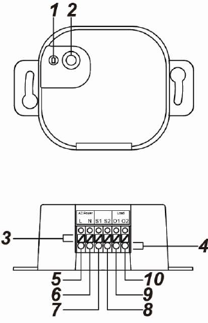
Parts Identification
1. LED indicator
The LED indicator is used to indicate Shutter Control status:
- Flashes once: The Shutter Control has reset.
- Flashes twice: The Shutter Control has successfully joined a
ZigBee network.
- Flashes once every 20 minutes:
The Shutter Control has lost connection to its current ZigBee
network.
2. Function Button
- Press once: Transmit a supervision signal.
- Press and hold for 3~10 seconds: Enter calibration mode.
- Press and hold for 10 seconds: Reset the Shutter Control to
join ZigBee network.
3. Insertion Hole Clipper Opener
Press the button to open the clipper of the respective insertion
hole
4. Wire Insertion Holes (With clippers)
5. Power Input Terminal L (Live Lead)
6. Power input Terminal N (Neutral Lead)
7. Local Switch Terminal S1 (Open Direction)
Connect an external switch to this terminal. Activate this switch to control
the shutter to roll toward “Open” direction by activating the Motor Output O1
Activating this switch when the shutter is rolling towards the “Close”
direction will stop the shutter.
8. Local Switch Terminal S2 (Close Direction)
Connect an external switch to this terminal. Activate this switch to control the
shutter to roll toward “Close” direction by activating the Motor Output O2
Activating this switch when the shutter is rolling towards the open direction
will stop the shutter.
9. Motor Output O1 (Open Direction)
Connect to the Open terminal of the Shutter Motor.
10. Motor Output O2 (Close Direction)
Connect to the Close terminal of the Shutter Motor.
ZigBee Network Setup
Z
Zi
ig
gB
Be
ee
e
D
De
ev
vi
ic
ce
e
G
Gu
ui
id
de
el
li
in
ne
e
ZigBee is a wireless communication protocol that is reliable, has low power consumption and has high
transmission efficiency. Based on the IEEE802.15.4 standard, ZigBee allows a large amount of devices to
be included in a network and are coordinated for data exchange and signal transmission.
2
J
Jo
oi
in
ni
in
ng
g
t
th
he
e
Z
Zi
ig
gB
Be
ee
e
N
Ne
et
tw
wo
or
rk
k
As a ZigBee device, the Shutter Control needs to join a ZigBee network to receive commands. Please
follow the steps bellow to join the Shutter Control into a ZigBee network.
1. Connect the power cable to AC Input connector on Shutter Control.
2. Press and hold the function button for 10 seconds as the Shutter Control resets and starts searching for
existing ZigBee network. Please make sure the permit-to-join feature on the router or coordinator of
your ZigBee network is enabled.
3. If the Shutter Control successfully joins a ZigBee network, the LED Indicator will flash twice to confirm.
4. After joining the ZigBee network, the Shutter Control will be registered in the network automatically.
Please check the ZigBee network coordinator, system control panel or CIE (Control and Indicating
Equipment) to confirm if joining and registration is successful.
5. After joining the ZigBee network, if the Shutter Control loses connection to the current ZigBee network,
the LED indicator will flash every 20 minutes. Please check your ZigBee network condition and Shutter
Control signal range to correct the condition.
Removing Device from ZigBee Network (Factory Reset)
To remove the Shutter Control from current ZigBee network, the Shutter Control must be put to Factory
Reset to complete device removal. Factory Reset function will clear the Shutter Control of its stored setting
information and prompt the device to search for new ZigBee network.
Before removing device, make sure the Shutter Control is within current ZigBee network signal
range
1. Press and hold the function button for 10 seconds, then release the button to reset Shutter Control.
2. Upon reset, the Shutter Control will clear current ZigBee network setting and transmit signal to ZigBee
coordinator to remove itself from current ZigBee network. It will then actively search for available
ZigBee network again and join the network automatically.
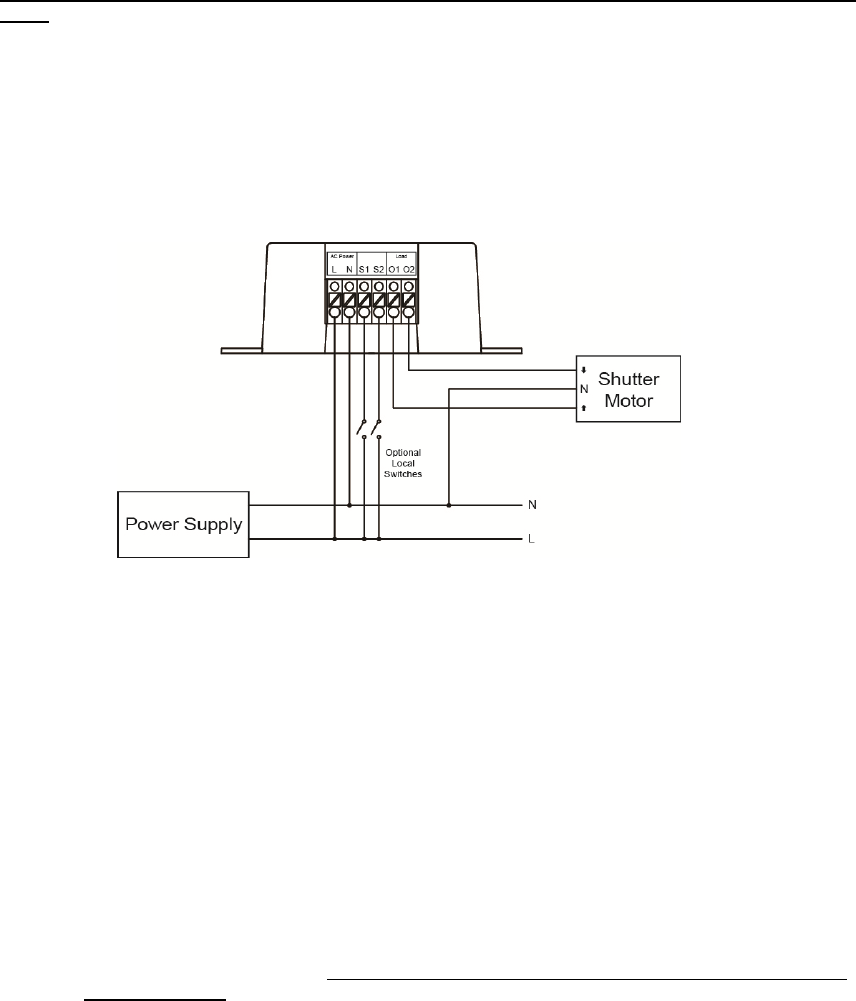
Installation
Please use the recommended wire size of AWG 16-26 or Ø 1.31-0.129 (mm²).
Connect SCM according to the diagram below:
Connect L terminal of SCM to the L terminal of Power Supply.
Connect N terminal of SCM to the N terminal of Power Supply.
Connect O1 terminal of SCM to the Open terminal of the Shutter Motor.
Connect O2 terminal of SCM to the Close terminal of the Shutter Motor.
(Optional local switch) Connect S1 and S2 terminals of SCM to the L terminal of Power Supply.
Operation
C
Ca
al
li
ib
br
ra
at
ti
io
on
n
The Shutter Control default activation time is 4 minutes. When the Up/Down button is pressed or the
ZigBee network coordinator transmits Up/Down command, it will activate the Shutter Motor for 4
minutes.
For the Shutter Control to work properly, its activation time must be calibrated. There are two ways to
adjust the activation time:
ZigBee Command: The activation time can be adjusted by sending command from the ZigBee
network coordinator. (See Appendix – Level Cluster Attribute – OnTransitionTime /
OffTransitionTime, minimum adjustable unit 100ms)

3
Manual Calibration: Calibrate the activation according to procedure below:
1. Before calibration, the external local switches must be connected to the Shutter Control.
2. Press and hold the Function button for 3~10 seconds and release to enter Calibration mode.
The Shutter Control will roll toward the “Open” direction for 4 minutes upon entering
Calibration mode.
3. Wait for 4 minutes for Shutter Control to stop rolling to “Open” direction, then activate the
connected external local “Close” switch to close the shutter.
4. Activate the “Open” external local switch the moment the shutter is fully closed. The Shutter
control will record to time it took between step 3 and 4 as the new “close time”.
5. The Shutter Control will roll toward open direction after step 4.
6. Activate the “Close” external local switch the moment the shutter is fully opened. The Shutter
control will record to time it took between step 5 and 6 as the new “open time”.
Example
If it takes 30 seconds for the shutter to move from Open to Close, and 40 seconds to move
from Close to Open, the new close time will be 30 seconds and new open time will be 40
seconds.
After calibration, whenever the Shutter Control receives close command, it will roll toward
close direction for 30 seconds. When it receives open command, it will roll toward open for
40 seconds.
The activation time will be reset to 4 minutes whenever the Shutter Control joins a ZigBee network.
S
Sh
hu
ut
tt
te
er
r
C
Co
on
nt
tr
ro
ol
l
ZigBee Network
After the Shutter Control has successfully joined a ZigBee network, the coordinator can remotely
control the shutter to open, close or stop by transmitting command though ZigBee network.
When the Shutter Control receives open/close signal from coordinator, it will roll toward open/close
direction according to calibrated activation time to fully open/close the shutter.
The Shutter status can also be adjusted by percentage from 0%, 10%, 20%... to 100% through
ZigBee Coordinator.
The current open percentage is also transmitted to ZigBee coordinator.
Local Switch
If an optional Local Switch is connected, users can also press the switch button to open/close the
shutter.
Press and release the switch for less than 1 second will control the shutter to fully open or close.
Press and hold the switch for more than 1 second will control the shutter to open and close until the
switch is released. When the switch is released, the shutter will stop.
Pressing the switch when the shutter is moving to opposite direction will stop the shutter. Press the
switch again to open/close the shutter.
For example, pressing the down switch when the shutter is opening will stop the shutter, press down
switch again to start closing the shutter.
M
Ma
ax
xi
im
mu
um
m
O
Op
pe
er
ra
at
ti
io
on
n
L
Lo
oa
ad
d
For 110V: the maximum operation load is 440W and 4A.
For 230V: the maximum operation load is 920W and 4A.
Appendix (For developers only)
P
Po
ow
we
er
r
R
Re
el
la
ay
y
S
Sh
hu
ut
tt
te
er
r
C
Co
on
nt
tr
ro
ol
l
w
wi
it
th
h
M
Me
et
te
er
r
C
Cl
lu
us
st
te
er
r
I
ID
D
Device ID: Shade :0x0200
Endpoint:0x01
Server Side Client Side
Mandatory
Basic (0x0000) None
Identify(0x0003)
On/Off(0x0006)
Level Control(0x0008)
Shade Config(0x0x0100)
Groups(0x0004)
Scenes(0x0005)
Optional

4
None None
A
At
tt
tr
ri
ib
bu
ut
te
e
o
of
f
B
Ba
as
si
ic
c
C
Cl
lu
us
st
te
er
r
I
In
nf
fo
or
rm
ma
at
ti
io
on
n
Identifier Name Type Range Access Default Mandatory
/ Optional
0x0000 ZCLVersion Unsigned 8-bit
integer 0x00 –0xff Read only 0x01 M
0x0001 ApplicationVersion Unsigned 8-bit
integer 0x00 – 0xff Read only 0x00 O
0x0003 HWVersion Unsigned 8-bit
integer 0x00 –0xff Read only 0 O
0x0004 ManufacturerName Character String 0 – 32 bytes Read only Climax
Technology O
0x0005 ModelIdentifier Character String 0 – 32 bytes Read only (Model Version) O
0x0006 DateCode Character String 0 – 16 bytes Read only O
0x0007 PowerSource 8-bit 0x00 –0xff Read only M
0x0010 LocationDescription Character String 0 – 32 bytes Read / Write O
0x0011 PhysicalEnvironment 8-bit 0x00 –0xff Read / Write 0x00 O
0x0012 DeviceEnabled Boolean 0x00 –0x01 Read / Write 0x01 M
A
At
tt
tr
ri
ib
bu
ut
te
e
o
of
f
I
Id
de
en
nt
ti
if
fy
y
C
Cl
lu
us
st
te
er
r
I
In
nf
fo
or
rm
ma
at
ti
io
on
n
Identifier Name Type Range Access Default Mandatory
/ Optional
0x0000 IdentifyTime Unsigned 16-bit
integer 0x00 –0xffff Read / Write 0x0000 M
A
At
tt
tr
ri
ib
bu
ut
te
e
o
of
f
O
On
n/
/O
Of
ff
f
C
Cl
lu
us
st
te
er
r
I
In
nf
fo
or
rm
ma
at
ti
io
on
n
Identifier Name Type Range Access Default Mandatory
/ Optional
0x0000 OnOff Boolean 0x00 –0x01 Read only 0x00 M
A
At
tt
tr
ri
ib
bu
ut
te
e
o
of
f
L
Le
ev
ve
el
l
C
Cl
lu
us
st
te
er
r
I
In
nf
fo
or
rm
ma
at
ti
io
on
n
Identifier Name Type Range Access Default Mandatory
/ Optional
0x0000 CurrentLevel Unsigned
8-bit integer 0x00 –0xff Read only 0x00 M
0x0012 OnTransitionTime Unsigned 16-bit
integer
0x0000 –
0xFFFF Read / Write 0x0960 O
0x0013 OffTransitionTime Unsigned 16-bit
integer
0x0000 –
0xFFFF Read / Write 0x0960 O
A
At
tt
tr
ri
ib
bu
ut
te
es
s
o
of
f
t
th
he
e
S
Sh
ha
ad
de
e
c
cl
lu
us
st
te
er
r
I
In
nf
fo
or
rm
ma
at
ti
io
on
n
Identifier Name Type Range Access Default Mandatory
/ Optional
0x0002 Status 8-bit bitmap 0000xxxx B Read / Write 00000000 B M
0x0010 ClosedLimit Unsigned 16-bit
integer
0x0001 –
0xfffe
Read / Write 0x0001 M
0x0011 Mode 8-bit Enumeration 0x00 – 0xfe Read / Write 0x00 M
A
At
tt
tr
ri
ib
bu
ut
te
es
s
o
of
f
t
th
he
e
G
Gr
ro
ou
up
ps
s
c
cl
lu
us
st
te
er
r
I
In
nf
fo
or
rm
ma
at
ti
io
on
n
Identifier Name Type Range Access Default Mandatory
/ Optional
0x0000 NameSupport 8-bit bitmap x0000000 Read only - M
A
At
tt
tr
ri
ib
bu
ut
te
es
s
o
of
f
t
th
he
e
S
Sc
ce
en
ne
es
s
c
cl
lu
us
st
te
er
r
I
In
nf
fo
or
rm
ma
at
ti
io
on
n
Identifier Name Type Range Access Default Mandatory
/ Optional
0x0000 SceneCount Unsigned 8-bit
integer 0x00 – 0xff Read only 0x00 M
0x0001 CurrentScene Unsigned 8-bit
integer 0x00 – 0xff Read only 0x00 M
0x0002 CurrentGroup Unsigned
16-bit integer
0x0000 –
0xfff7 Read only 0x00 M
0x0003 SceneValid Boolean 0x00 – 0x01 Read only 0x00 M
0x0004 NameSupport 8-bit bitmap x0000000 Read only - M
5
Federal Communication Commission Interference Statement
This equipment has been tested and found to comply with the limits for a
Class B digital device, pursuant to Part 15 of the FCC Rules. These limits are
designed to provide reasonable protection against harmful interference in a
residential installation.
This equipment generates, uses and can radiate radio frequency energy and,
if not installed and used in accordance with the instructions, may cause
harmful interference to radio communications. However, there is no
guarantee that interference will not occur in a particular installation. If this
equipment does cause harmful interference to radio or television reception,
which can be determined by turning the equipment off and on, the user is
encouraged to try to correct the interference by one of the following
measures:
. Reorient or relocate the receiving antenna.
. Increase the separation between the equipment and receiver.
. Connect the equipment into an outlet on a circuit different from that to
which the receiver is connected.
. Consult the dealer or an experienced radio/TV technician for help.
FCC Caution
: To assure continued compliance, any changes or modifications
not expressly approved by the party responsible for compliance could void
the user's authority to operate this equipment. (Example - use only shielded
interface cables when connecting to computer or peripheral devices).
FCC Radiation Exposure Statement
This equipment complies with FCC RF radiation exposure limits set forth for
an uncontrolled environment. This equipment should be installed and
operated with a minimum distance of 20 centimeters between the radiator
and your body.
This transmitter must not be co-located or operating in conjunction with
any other antenna or transmitter.
The antennas used for this transmitter must be installed to provide a
separation distance of at least 20 cm from all persons and must not
be co-located or operating in conjunction with any other antenna or
transmitter.
This device complies with Part 15 of the FCC Rules. Operation is subject to
the following two conditions:
(1) This device may not cause harmful interference, and
(2) This device must accept any interference received, including interference
that may cause undesired operation.