Climax Technology Co SDC1 Slim Door Contact User Manual SDC 1 20180425 FCCx
Climax Technology Co Ltd Slim Door Contact SDC 1 20180425 FCCx
Users Manual

Slim Door Contact (SDC-1) User Manual
The Slim Door Contact monitors the opening/closing of specified devices (e.g. door or window). The Door Contact is fixed to
the monitored device frame with an actuating magnet fixed to the device. When the door or window opens, the magnet
moves away from the Door Contact, activating an internal magnetic switch causing the Door Contact to transmit alarm signal
to the Control Panel. The device also has the capabilities of communicating signal problems along with low battery situations.
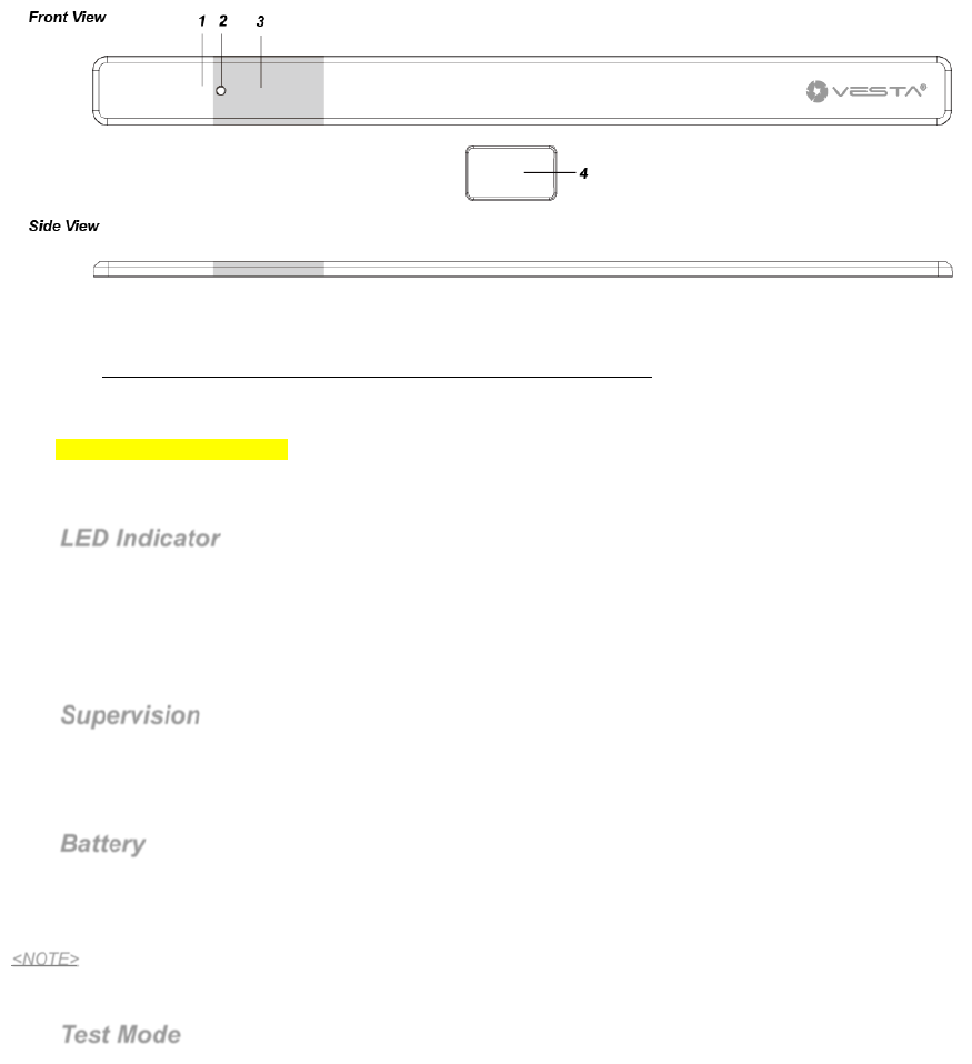
Identifying the parts
1. LED Indicator
2. Learn/Test Button
*(Use a sharp tool such as a paper clip to press the Learn/Test button).
- Press the button to transmit a learn code.
- Press the button once to enter Test Mode for 3 minutes.
3. Magnet Detection Area
4. Magnet
- Please refer to Magnet Scope Positioning for how to use the magnet with the Door Contact correctly.
LED Indicator
In Normal operation mode, the LED indicator remains off except in the following situations:
When the Door Contact is activated under Low battery condition.
When the Door Contact is activated and transmitting the signal under the Test mode.
Features
Supervision
The Door Contact will automatically transmit supervision signals to the Control Panel at random intervals of
30 to 50 minutes in Normal Operation Mode.
If the Control Panel has not received the signal from the Door Contact for a preset period time, the Control
Panel will indicate that the Door Contact is experiencing an out-of-signal problem.
Battery
The Door Contact uses a pack of 10 x CR1616 battery as power source
The Door Contact is also capable of detecting low battery condition. When the battery is low, a low battery
signal will be sent to the Control Panel along with regular transmission. The LED will light up when the Door
Contact is activated under low battery status.
<NOTE>
The pre-inserted battery in the Slim Door Contact cannot be replaced or switched out.
Test Mode
The Door Contact can be put into Test mode for 3 minutes by pressing the Learn/Test Button once.
During Test mode, the LED indicator will light up upon triggering.
Each press on the Test Button will lead the Door Contact to transmit a test signal to the Control Panel for
radio range test and reset the test mode to the 3-minute duration.
The Door Contact will automatically exit Test Mode after the 3-minute duration and return to Normal
Operation mode.
1

Getting Started
Pairing and Installation
Step 1: Put the Control Panel into learning mode, refer to the Control Panel manual for detail.
Step 2: Press the Learn/Test Button on Door Contact to send signal to the Control Panel.
Step 3: If the Control Panel successfully receives the signal, the Control Panel will respond (e.g. emitting beeps).
Refer to your Control Panel manual to complete the learning process.
Step 4: After the Door Contact is learnt-in, put the Control Panel into “Walk Test” mode, hold the Door Contact at
the desired location, and press the Learn/Test button to confirm if this location is within signal range of the
Control Panel.
Step 5: When you are satisfied with the Door Contact at the chosen location, remove paper backing of the
adhesive tape on the back of the Door Contact.
Step 6. Apply the Door Contact to your chosen location
Step 7. Remove the paper backing of the adhesive tape on the magnet
Step 8. Apply the magnet on a mobile object, e.g. the door/window. The magnet must be aligned with the Door
Contact (Please refer to Magnet Scope Positioning below.)
<NOTE>
The 3M adhesive tape cannot be reused.
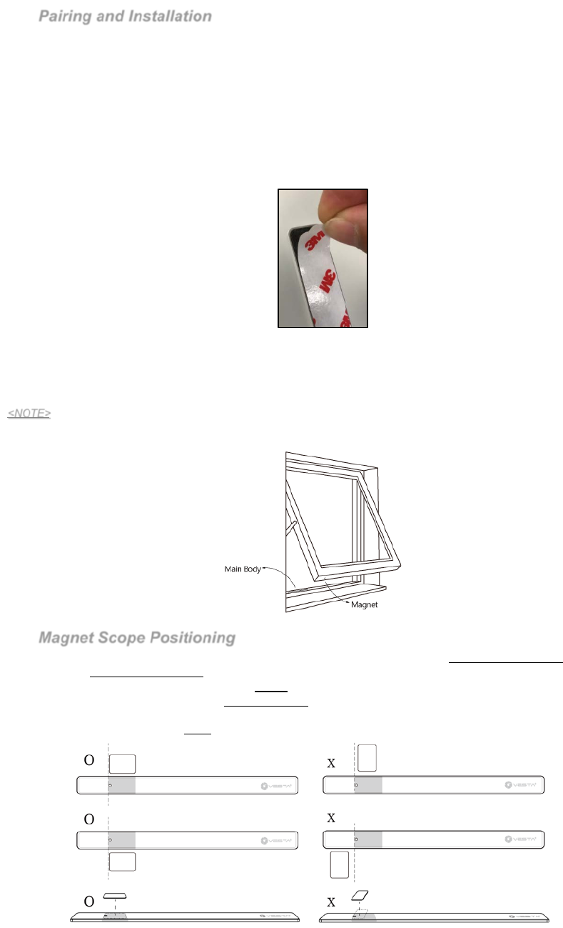
Magnet Scope Positioning
The Learn/Test Button located on the front side of Door Contact is the main magnet detection area.
The magnet detection area is polished for easy identification.
The magnet should be no more than 15mm from the detector when the door/window is closed.
The magnet should be applied vertically parallel to the Door Contact as pictures shown below.
When installing within a door / window slot (similar as image above), the window and window frame spacing
should be greater than 5mm, or the window cannot be properly closed.
2
This device complies with Part 15 of the FCC Rules. Operation is subject to the following
two conditions:
(1) This device may not cause harmful interference, and
(2) This device must accept any interference received, including interference that may
cause undesired operation.
3