Climax Technology Co SRACZB AC Powered Indoor Siren User Manual
Climax Technology Co Ltd AC Powered Indoor Siren Users Manual
UserManual.wiki
>
Climax Technology Co
>
SRACZB User Manual
Users Manual
Navigation menu
Upload a User Manual
Namespaces
Wiki Guide
HTML
PDF
Info
Views
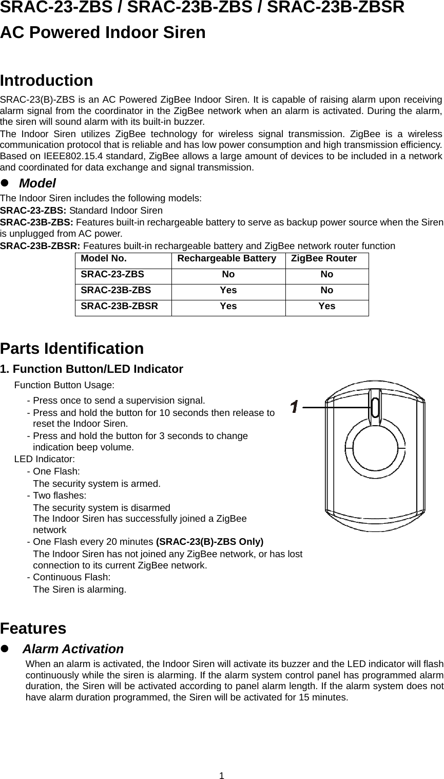
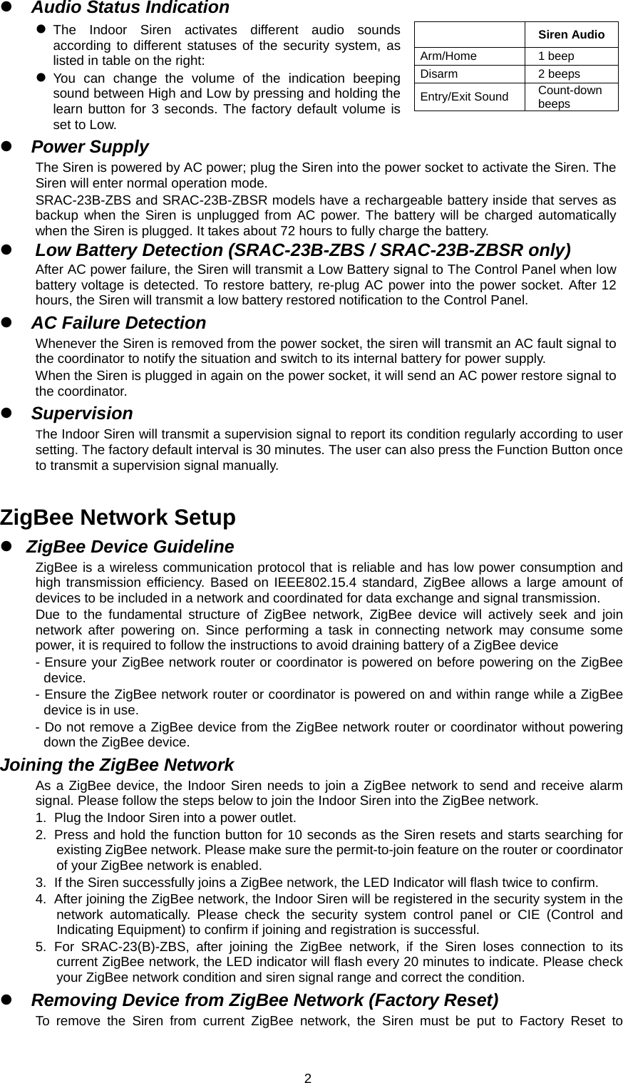
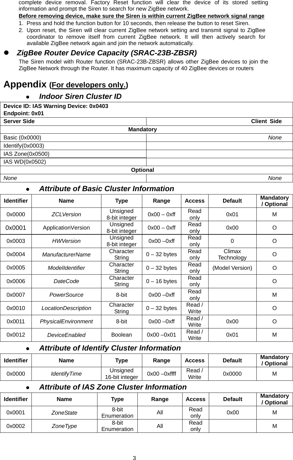
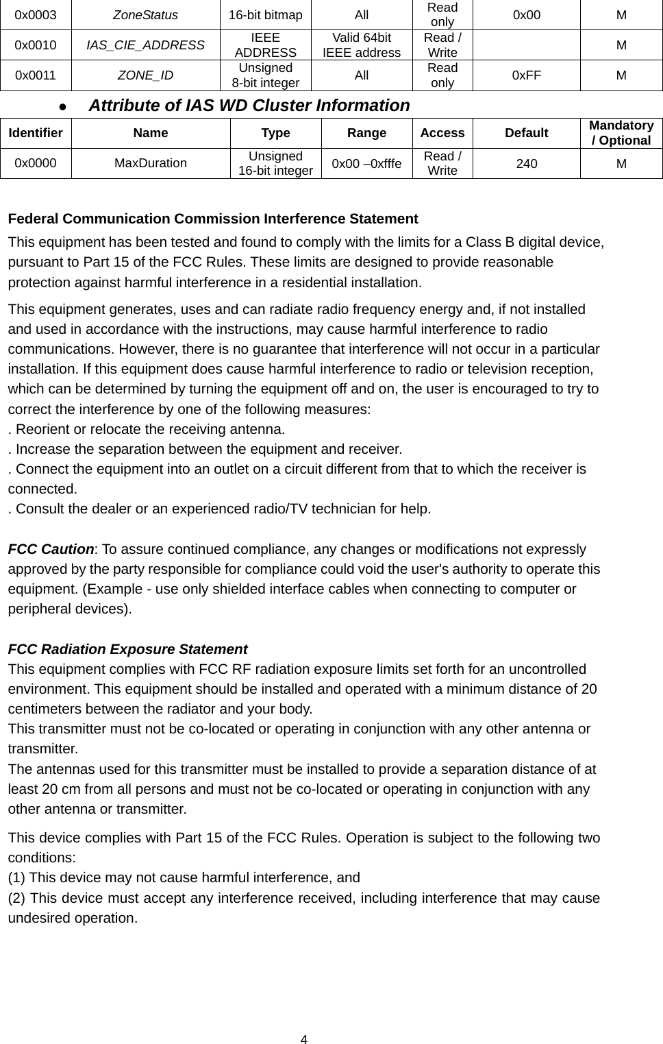
User Manual
Discussion / Help
Navigation