Climax Technology Co SVGS Shock, Vibration & Glass break sensor User Manual SVGS 1ZBS 20160310
Climax Technology Co Ltd Shock, Vibration & Glass break sensor SVGS 1ZBS 20160310
Users Manual
SVGS-1ZBS Shock, Vibration & Glass break sensor
SVGS-1ZBS is a ZigBee Shock, Vibration/Glass Break Sensor. It is capable of sending wireless signals to the coordinator in the
ZigBee network upon detection of window glass break or shock vibration detection.
The Sensor utilizes ZigBee technology for wireless signal transmission. ZigBee is a wireless communication protocol that is
reliable and has low power consumption and high transmission efficiency. Based on the IEEE 802.15.4 standard, ZigBee allows
a large amount of devices to be included in a network and coordinated for data exchange and signal transmission.
The Sensor serves as an end device in the ZigBee network. It can be included in the ZigBee network to transmit signal upon
activation, but cannot permit any other ZigBee device to join the network through the Sensor.
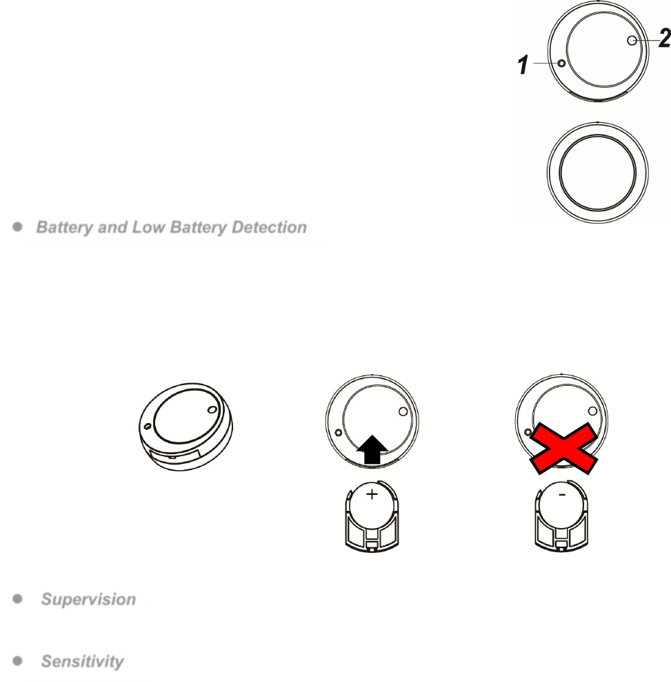
Parts Identification
1. Function Button
Using sharp tools such as paper clip to press and hold the Function Button for 10
seconds to send learning signal to the Control Panel / or Reset to factory
settings.
2. LED Indicator
The LED indicator lights up in the following conditions:
LED flash Once: The Sensor has been reset.
LED flash Twice: The Sensor has successfully joined ZigBee network.
Features
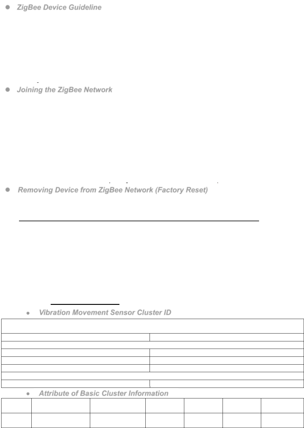
Battery and Low Battery Detection
The Sensor use one CR2032 3V Lithium battery as its power source. Please note: ALWAYS replace battery with the
correct size and voltage.
The Sensor can detect if the battery is low. When the Battery is low, a low battery signal will be sent to the Control
Panel along with regular transmission.
When changing battery, use a sharp tool to open the battery slot to remove and insert battery.
When inserting batteries, the positive(+) side of the battery must face upward. NEVER insert the battery with
negative(-) side facing upward.
Supervision
The
Sensor will transmit a supervision signal to report its condition regularly according to the user’s setting. The factory
default interval is 30 minutes. The user can also press the Function Button once to transmit a supervision signal manually.
Sensitivity
The Sensor can send alarm signal to the Control Panel according to different sensitivity levels set in the Control Panel.
The Sensitivity levels include high, medium, and low (default is medium), the higher the sensitivity the easier to trigger the
Sensor when window/glass break or shock vibration detected.
Please use sharp tools such as a paper clip and to press the Sensor’s function button once. The Sensor will wake up
(for 1 minutes) and send test signal to the Control Panel before setting sensitivity.
Start setting sensitivity level on the Control Panel (Please refer to your Control Panel for details).
ZigBee Network Setup
ZigBee Device Guideline
ZigBee is a wireless communication protocol that is reliable and has low power consumption and high transmission
efficiency. Based on IEEE802.15.4 standard, ZigBee allows a large amount of devices to be included in a network and
coordinated for data exchange and signal transmission.
Due to the fundamental structure of ZigBee network, ZigBee device will actively seek and join network after powering on.
Since performing a task in connecting network may consume some power, it is required to follow the instructions to avoid
draining battery of a ZigBee device.
- Ensure your ZigBee network router or coordinator is powered on before inserting battery into the ZigBee device.
- Ensure the ZigBee network router or coordinator is powered on and within range while a ZigBee device is in use.
- Do not remove a ZigBee device from the ZigBee network router or coordinator without removing the battery from a
ZigBee device.
Joining the ZigBee Network
As a ZigBee device, the Sensor needs to join a ZigBee network to transmit signal when it is triggered. Please follow the
steps bellow to join the Sensor into the ZigBee network.
1. Remove the insulator from the Sensor to power on.
2. After powering up, use sharp tools such as a paper clip to press and hold the Function button for 10 seconds until LED
flash once, then release it to join the network. Please make sure the permit-join feature on the router or coordinator of
your ZigBee network is enabled.
3. If the Sensor successfully joins a ZigBee network, the LED Indicator will flash twice to confirm (refer to you Control
Panel to complete learning).
4. After joining the ZigBee network, the Sensor will be registered in the network automatically. Please check the ZigBee
coordinator, system control panel or CIE (Control and Indicating Equipment) to confirm if joining and registration is
successful.
5. After joining the ZigBee network, if the Sensor loses connection to current ZigBee network, the LED will flash every 20
minutes to indicate. Please check your ZigBee network condition and Sensor signal range to correct the situation.
Removing Device from ZigBee Network (Factory Reset)
To remove the Sensor from current ZigBee network, the Sensor must be put to Factory Reset to complete device removal.
Factory Reset function will clear the Sensor of its stored setting and information and prompt the Sensor to search for new
ZigBee network.
Before removing device, make sure the Sensor is within current ZigBee network signal range
1. Press and hold the function button for 10 seconds, then release the button to reset Sensor.
2. Upon reset, the Sensor will clear current ZigBee network setting and transmit signal to ZigBee coordinator to remove
itself from current ZigBee network. It will then actively search for available ZigBee network again and join the network
automatically.
Installation
The Sensor should be installed on a glass to detect shock/vibration or glass breakage. Use the double side adhesive tape
provided to secure the Sensor on the window.
Appendix (For developers only)
Vibration Movement Sensor Cluster ID
Device ID: IAS Zone 0x402
Endpoint: 0x01
Server Side Client Side
Mandatory
Basic (0x0000) Basic (0x0000)
Identify(0x0003)
IAS Zone(0x0500)
Optional
None None
Attribute of Basic Cluster Information
Identifier
Name Type Range Access Default Mandatory /
Optional
0x0000 ZCLVersion Unsigned 8-bit
integer 0x00 –0xff Read only 0x01 M
0x0001 ApplicationVersion Unsigned 8-bit
integer 0x00 –0xff Read only 0x00 O
0x0003 HWVersion Unsigned 8-bit
integer 0x00 –0xff Read only 0 O
0x0004 ManufacturerName Character String 0 – 32 bytes
Read only Climax
Technology O
0x0005 ModelIdentifier Character String 0 – 32 bytes
Read only (Model
Version) O
0x0006 DateCode Character String 0 – 16 bytes
Read only O
0x0007 PowerSource 8-bit 0x00 –0xff Read only M
0x0010 LocationDescription
Character String 0 – 32 bytes
Read / Write
O
0x0011 PhysicalEnvironment
8-bit 0x00 –0xff Read / Write
0x00 O
0x0012 DeviceEnabled Boolean 0x00 –0x01
Read / Write
0x01 M
Attribute of Identify Cluster Information
Identifier
Name Type Range Access Default Mandatory /
Optional
0x0000 IdentifyTime Unsigned 16-bit
integer 0x00 –0xffff
Read / Write
0x0000 M
Attribute of IAS Zone Cluster Information
Identifier
Name Type Range Access Default Mandatory /
Optional
0x0001 ZoneState 8-bit Enumeration All Read only 0x00 M
0x0002 ZoneType 8-bit Enumeration All Read only M
0x0003 ZoneStatus 16-bit bitmap All Read only 0x00 M
0x0010 IAS_CIE_ADDRESS
IEEE ADDRESS
Valid 64bit
IEEE
address
Read / Write
M
0x0011 ZONE_ID Unsigned 8-bit
integer All Read only 0xFF M
0x1000 VibrationSensitivity Unsigned 8-bit
integer 0x01 – 0x03
Read / Write
0x02 O
Federal Communication Commission Interference Statement
This equipment has been tested and found to comply with the limits for a Class B digital device,
pursuant to Part 15 of the FCC Rules. These limits are designed to provide reasonable protection
against harmful interference in a residential installation.
This equipment generates uses and can radiate radio frequency energy and, if not installed and used in
accordance with the instructions, may cause harmful interference to radio communications. However,
there is no guarantee that interference will not occur in a particular installation. If this equipment does
cause harmful interference to radio or television reception, which can be determined by turning the
equipment off and on, the user is encouraged to try to correct the interference by one of the following
measures:
. Reorient or relocate the receiving antenna.
. Increase the separation between the equipment and receiver.
. Connect the equipment into an outlet on a circuit different from that to which the receiver is
connected.
. Consult the dealer or an experienced radio/TV technician for help.
FCC Caution: To assure continued compliance, any changes or modifications not expressly approved by
the party responsible for compliance could void the user's authority to operate this equipment.
(Example - use only shielded interface cables when connecting to computer or peripheral devices).
FCC Radiation Exposure Statement
This equipment complies with FCC RF radiation exposure limits set forth for an uncontrolled
environment. This equipment should be installed and operated with a minimum distance of 20
centimeters between the radiator and your body.
This transmitter must not be co-located or operating in conjunction with any other antenna or
transmitter.
The antennas used for this transmitter must be installed to provide a separation distance of at least 0.5
cm from all persons and must not be co-located or operating in conjunction with any other antenna or
transmitter.
This device complies with Part 15 of the FCC Rules. Operation is subject to the following two conditions:
(1) This device may not cause harmful interference, and (2) This device must accept any interference
received, including interference that may cause undesired operation.