Climax Technology Co TGF1 NFC Reader User Manual TG 15 F1 20160127 FCCx
Climax Technology Co Ltd NFC Reader TG 15 F1 20160127 FCCx
Users Manual

1
Tag Reader (TG-15 F1)
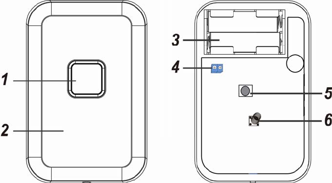
Identifying the parts:
1. Power LED (Green)
Status LED (Red)
Arm Button
2. Tag Reader Sensor
(for tag)
3. Power Terminal
(5V DC Adapter)
4. Battery Compartment
5. Learn Button
6. Tamper
LED Indicator:
Mode (Green LED):
Flash: When Control Panel is under Arm Mode.
OFF: When Control Panel is under Disarm Mode.
System Status (Red LED) :
Flash 5 times: Learning failed or no response from Control Panel.
OFF: When Control Panel is under Disarm Mode.
Continuous flash: When alarming.
Power:
The Tag Reader is powered by AC Adapter 5V or by inserting batteries. Wire the 5V DC Adapter
to the power terminal on the Tag Reader or use two AA 1.5V L91 Lithium batteries as power
source.
When Both AC Adapter and batteries are in use, the Tag Reader will only power on through AC
Adapter.
The Tag Reader can also detect the battery status when batteries are inserted.
If the battery voltage is low during operation, the low battery signal will be sent to the Control
Panel along with regular signal transmissions for the Control Panel to display the status
accordingly.
If battery voltage is exhausted, both Green and Red LED will flash every 4 seconds and the Tag
Reader will stop all operation.
Power Saving Feature:
When idle, Tag Reader is in “power saving” mode and uses no power. It will activate and
“wake-up” for 6 seconds when put the tag on the Tag Reader sensor.
After 6 seconds of inactivity, the power goes off and it returns to power saving mode.
Supervision:
Tag Reader will transmit a supervision signal to report its condition regularly every 30 ~ 45
minutes
Tamper Protection:
Tag Reader is protected against any attempt to open the lid or to detach Tag Reader from its

2
mounting surface (see Mounting Tag Reader for details).
When Tag Reader’s tamper is triggered, a tamper signal will be sent to the Control Panel for the
Control Panel to display the status. Once the signal is sent, Tag Reader returns to power saving
mode.
Getting Started:
Step 1. Remove the cover by losing the fixing screw.
Step 2. Power on the Tag Reader (see Power for details).
Step 3. Adding Tag Reader into the Control Panel:
(a) Put Control Panel into Learning Mode (Refer to the operation manual of your Control Panel
for details), then Remove the Tag Reader’s cover.
(b) Press the Learn Button, Tag Reader will emit a beep and its info will display in the Control
Panel.
(c) Press the Add button, the Control Panel will send acknowledgement back to Tag Reader
and it will emit 3 beeps to indicate successful learning.
(c) If the Add button is not pressed within 10 seconds, Tag Reader will transmit a failed signal
with Red LED flashing 5 times. Please press the Learn Button again to learn into the
Control Panel.
Step 4. Navigate the Control Panel into “Walk Test” mode. Hold the Tag Reader in the desired
location, and put the tag near Tag Reader tag sensor with 1 beep sound, to confirm this
location is within signal range of the Control Panel, if success the Tag Reader will emit 3
beeps.
Step 5. When you are satisfied that the Tag Reader works in the chosen location, you can proceed
to mount the Tag Reader by following the below steps.
Mounting Tag Reader:
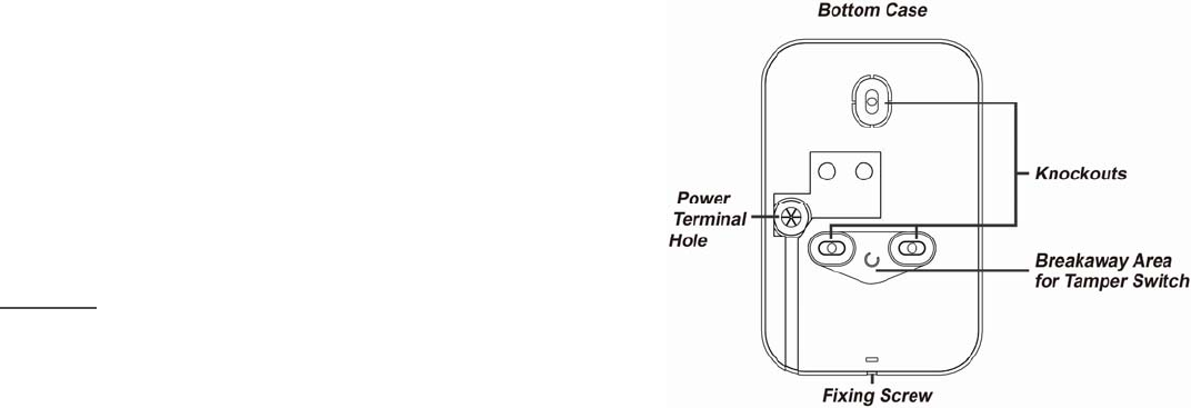
The Tag Reader consists of a two-part design made up of a cover and base. The cover contains all
the electronics and the base provides a mean of fixing. The tamper switch protects the enclosure
from being opened or being removed from the mounting surface.
The base has three knockouts for mounting purpose. To mount the Tag Reader:
I. Remove the fixing screw at the bottom
II. Remove the cover assembly
III. Break through the appropriate knockouts on the
mounting holes.
IV. Use the Mounting holes of the base as a template,
drill holes in the surface.
V. Insert the wall plugs if fixing into plaster or brick
VI. Screw the base into the wall plugs
VII. Fix the cover with the screw and clips to the base
<NOTE>
If the mounted Tag Reader is forcedly removed,
the Breakaway Area will be left on the wall
separated from the Tag Reader, the tamper will
then be triggered (only available by using the
Mounting Holes method).
When connecting with an AC Adapter through the power terminal, pull the two-wired power
adapter through the power terminal hole before using the Tag Reader.
Tag Learning
After first power on the Tag Reader, please wait for 10 seconds for Tag Reader to enable tag sensor
function.
Please start learning the tag into the Control Panel, follow the steps as below:

3
Step 1. Put Control Panel into Tag Learning Mode (Please refer to you Control Panel for details).
Step 2. Place the tag near the Tag Reader Sensor to record a tag ID into the Control Panel.
Step 3. The Tag Reader will emit 4 beeps to indicate a learning signal is sent to the Control Panel. If
Control Panel successfully received the tag ID, tag information will be displayed on the
Control Panel. If Control Panel fails to receive tag ID, Tag Reader’s Red LED will flash 5
times.
<NOTE>
If Tag Reader has not yet learned into the Control Panel, placing the tag near the Tag Reader
Sensor will emit 2 beeps indicating no transmission has been sent.
Operation:
After you complete learning the tag into the Control Panel, you can now switch the system to Arm,
Disarm Mode:
a) Disarm Mode Control: Apply tag near Tag Reader Sensor, the Control Panel will
automatically switch to Disarm Mode, the Tag Reader will emit 2 beeps.
b) Arm Mode Control: Press the Arm Button once, the Green LED will quickly flash for 5
seconds, then apply tag near Tag Reader Sensor, the Tag Reader will emit 1 long beep for
3 seconds to indicate arming success.
c) LED flash: If system is Armed, Green LED will light on for 3 seconds, after 3 seconds it will
continuously flash. When Disarmed, Green and Red LED will be off.
d) Alarm: The Red LED continuous flash when alarm is triggered.
e) Tamper: When Tamper is triggered, the Tag Reader will transmit tamper alarm signal to the
Control Panel immediately and returns to power saving mode.
Changing Battery:
Step 1: Remove the Tag Reader cover by losing the fixing screw.
Step 2: Remove the old batteries.
Step 3: Press Learn button to fully discharge.
Step 4: Insert new batteries. The Tag Reader will emit one beep to indicate.
Step 5. Press Learn button again to send low battery restore to Control Panel.
Step 6: Fix the cover with the screw and mount back to its location.
Factory Default (Reset Learning Record):
Step 1: Remove the cover by losing the fixing screw.
Step 2: Remove battery, then press the Learn Button and insert the batteries to power back on.
Step 3: The Tag Reader will be removed from the Control Panel until it emits 3 beeps.
4
Federal Communication Commission Interference Statement
This equipment has been tested and found to comply with the limits for a Class B digital device, pursuant
to Part 15 of the FCC Rules. These limits are designed to provide reasonable protection against harmful
interference in a residential installation.
This equipment generates, uses and can radiate radio frequency energy and, if not installed and used in
accordance with the instructions, may cause harmful interference to radio communications. However,
there is no guarantee that interference will not occur in a particular installation. If this equipment does
cause harmful interference to radio or television reception, which can be determined by turning the
equipment off and on, the user is encouraged to try to correct the interference by one of the following
measures:
. Reorient or relocate the receiving antenna.
. Increase the separation between the equipment and receiver.
. Connect the equipment into an outlet on a circuit different from that to which the receiver is connected.
. Consult the dealer or an experienced radio/TV technician for help.
FCC Caution: To assure continued compliance, any changes or modifications not expressly approved by
the party responsible for compliance could void the user's authority to operate this equipment. (Example -
use only shielded interface cables when connecting to computer or peripheral devices).
This device complies with Part 15 of the FCC Rules. Operation is subject to the following two conditions:
(1) This device may not cause harmful interference, and (2) This device must accept any interference
received, including interference that may cause undesired operation.