Climax Technology Co TMSTZB Thermostat User Manual
Climax Technology Co Ltd Thermostat Users Manual
Users Manual
1
TMST-2B-ZBS Thermostat
Introduction
TMST-2B-ZBS is a battery powered ZigBee Thermostat. It is designed to be incorporated into household
heating and cooling system for home environment control. The Thermostat can be operated manually
using the LCD screen and buttons, or accessed remotely via ZigBee network. It feature Cooling, Heating,
Auto modes with temperature set point and automatic schedule for you to control your home
environment easily.
The Thermostat utilizes ZigBee technology for wireless signal transmission. ZigBee is a wireless
communication protocol that is reliable and has low power consumption and high transmission efficiency.
Based on the IEEE802.15.4 standard, ZigBee allows a large amount of devices to be included in a
network and coordinated for data exchange and signal transmission
The Thermostat serves as an end device in the ZigBee network. It can be included in the ZigBee network
to transmit signal upon activation, but cannot permit any other ZigBee device to join the network through
the Thermostat.
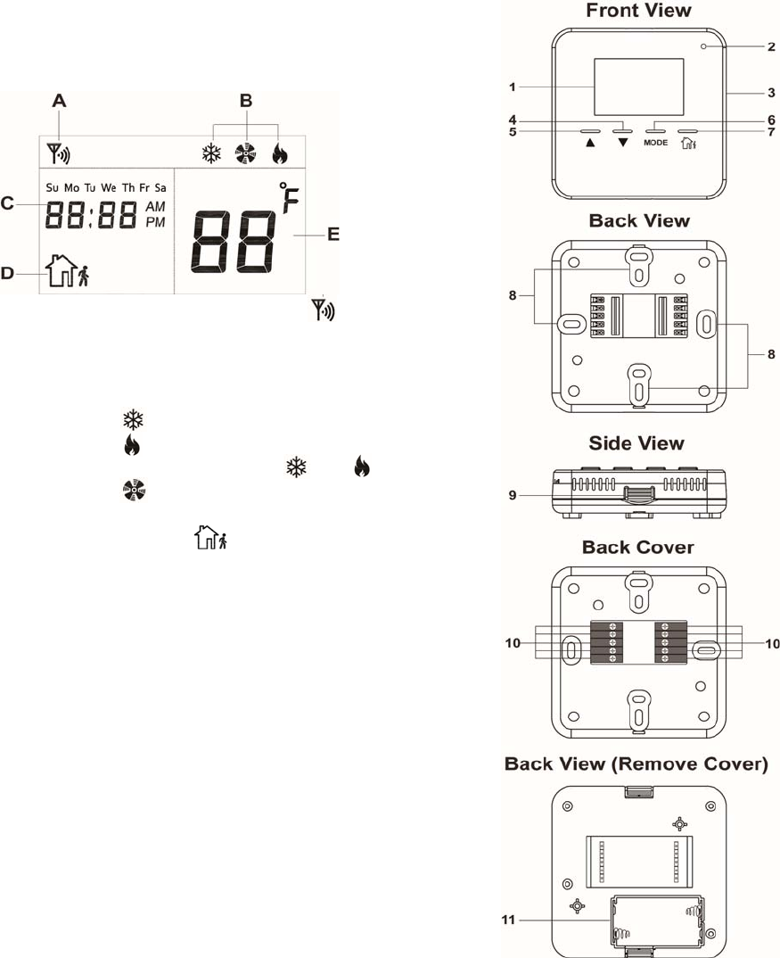
Parts Identification
1. LCD Display
The LCD displays the following information:
A. ZigBee network connectivity icon will be displayed
when the Thermostat has joined ZigBee network and is
within signal range.
B. The current mode will be displayed when the Up, Down or
Mode button is pressed.
Cool:
Heat:
Auto: Interval flash between and
Fan:
C. Current time and weekday
D. Away mode icon will be displayed when Thermostat
is under Away mode.
E. The temperature can displayed in Celsius or Fahrenheit
format.
2. Low Battery LED Indicator
The LED flashes when low battery voltage is detected
3. Test / ZigBee Network Button
- Press the button once to:
Send a supervision signal with temperature and set point info.
- Press and hold for 10 seconds then release to reset the Thermostat.
4. Down Button
Press the button to change set point.
5. Up Button
Press the button to change set point.
6. Mode Button
Press the button to change Thermostat mode.
2
7. Away Button
Press the button to change Thermostat to Away Mode.
8. Wall Mounting Holes
9. Back Cover Latch
Press both latches on the back cover to remove cover if needed.
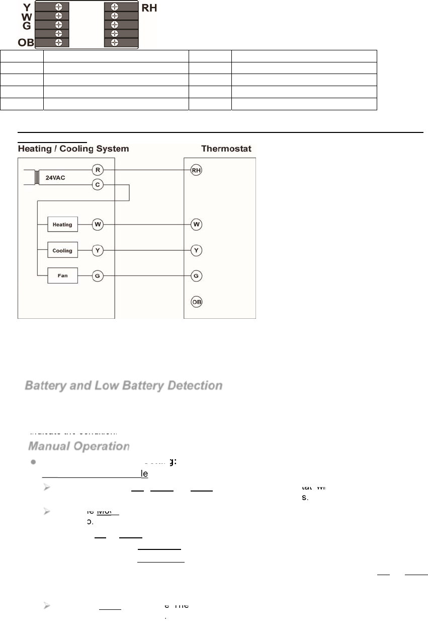
10. Wiring Connection Terminals
Name Description Name Description
Y Cooling RH 24VAC Power Input
W Heating
G Fan
OB Reversing Valve
Refer to Wiring Diagram below for detail.
Wiring of the Thermostat should be performed by a certified technician with proper equipment
to ensure safety
11. Battery Compartment
Insert 2 AA Alkaline batteries to power on the Thermostat.
Features
Battery and Low Battery Detection
The Thermostat uses 2 AA Alkaline batteries as its power source. The Thermostat features Low
Battery Detection function. When the battery voltage is low, the Thermostat will transmit Low
Battery signal to the coordinator in ZigBee network. The Low Battery LED will also begin to flash to
indicate the condition.
Manual Operation
Mode and Temperature Setting:
Cool, Heat and Auto Mode
Press any of the UP, Down or Mode button, the Thermostat will display current mode,
temperature set point and light up LCD backlight for 4 seconds.
Press the Mode button again during this period to set Thermostat mode between Cool, Heat
and Auto.
Press the Up or Down button to select temperature set point.
Heat setpoint range: 9˚C ~ 30˚C.
Cool setpoint range: 11˚C ~ 32˚C.
When under Auto mode, you will first select Auto Cool set point and pressing UP or Down
button, press Mode button again to select to Auto Heat set point. The Cool set point must be
at least 2℃ higher then Heat set point.
Press the Mode button The Thermostat will exit setting screen and apply the new setting
after 4 seconds of inactivity.
3
Away Mode
The Thermostat can be put into Away mode when the user leaves the house by pressing the
Away button.
To program Away Mode setting, press and hold Mode button for 3 seconds. You will first
program Away Cool set point, press Mode button after finish setting to program Away Heat
set point, the Cool set point must be at least 2℃ higher then Heat set point. Press Mode
button again to program Fan setting when done.
Fan Setting
When in Fan setting, press UP or Down button to select fan option between Always on or
Auto mode.
Always On ( icon steady on) – The fan is always turned on except under Off Mode
Auto mode ( icon flash) – The fan will be turned on according to Away, Cool and Heat
mode setting.
Off Mode
The Thermostat can be put into Off mode by pressing and holding the Away button for 3
seconds. When under Off mode, the Thermostat stop all function and only display current time.
Time / Temperature Display / HVAC Type Setting:
Press and hold the Mode button for 10 seconds to enter setting mode. The time on LCD display
will begin to flash:
Use the Up and Down buttons to select time and Mode button to proceed to next option.
Available options include:
1.
Weekday
2.
Hour
3.
Minute,
4.
AM/PM or 24-hour format display. (You can only change the time display format when
the time is set to between 1:01~12:59)
5.
Celsius or Fahrenheit display
6.
HVAC type: Type 1 = Gas/Electric, Type 2 = Heat Pump(O), Type 3 = Heat Pump(B).
Factory Default HVAC Type = 1 Gas/Electric
HVAC Type
According to the HVAC system in the home environment, select the HVAC type in Thermostat
setting.
Type 1: General Gas/Electric HVAC system
Type 2: HVAC system with Reversing Valve which operates during Cooling (Heat Pump “O”)
Type 3: HVAC system with Reversing Valve which operates during Heating (Heat Pump “B”)
Remote Control
After the Thermostat joins a ZigBee network, you can control the Thermostat via ZigBee network
coordinator or gateway. Please refer to your ZigBee coordinator/gateway manual for more
information.
The following functions are only available for setting via ZigBee coordinator and gateway:
Schedule:
You can only program Schedule configuration via ZigBee network coordinator/gateway.
Schedule Setting: Up to 5 schedules can be programmed for every weekday with Mode,
Setpoint and Start time.
Schedule Control:
Normal - The Thermostat will execute programmed schedule setting accordingly.
Hold – The Thermostat will bypass currently timed schedule and perform the next schedule
when it begins
No Schedule – The Thermostat will not execute any set schedule until it is set to Normal again.
Temperature Detection
The Thermostat has built-in temperature sensors and will display the temperature reading on
the LCD display
The Thermostat will transmit temperature signals regularly according to setting. The factory
default interval is 10 minutes.
When the temperature changes by +/- 2˚C, the Thermostat will also transmit a signal.
You can also press the ZigBee Network Button once to transmit a temperature signal manually.
4
Supervision
The Thermostat will transmit a supervision signal every 10 minutes along with the temperature,
current mode and set point information to report its condition regularly.
ZigBee Network Setup
ZigBee Device Guideline
ZigBee is a wireless communication protocol that is reliable and has low power consumption and
high transmission efficiency. Based on IEEE802.15.4 standard, ZigBee allows a large amount of
devices to be included in a network and coordinated for data exchange and signal transmission.
Due to the fundamental structure of ZigBee network, ZigBee device will actively seek and join
network after powering on. Since performing a task in connecting network may consume some
power, it is required to follow the instructions to avoid draining battery of a ZigBee device
- Ensure your ZigBee network router or coordinator is powered on before inserting battery into the
ZigBee device.
- Ensure the ZigBee network router or coordinator is powered on and within range while a ZigBee
device is in use.
- Do not remove a ZigBee device from the ZigBee network router or coordinator without removing
the battery from a ZigBee device.
Joining the ZigBee Network
As a ZigBee device, the Thermostat needs to join a ZigBee network to for user to control it remotely.
Please follow the steps bellow to join the Thermostat into the ZigBee network.
1. Remove the Thermostat back cover and insert 2 AA Alkaline batteries to power up the
Thermostat.
2. Press and hold the ZigBee network button for 10 seconds then release to join ZigBee network.
Please make sure the permit-join feature on the router or coordinator of your ZigBee network is
enabled.
3. Wait for several seconds for the Thermostat to join ZigBee network, if the Thermostat successfully
joins a network, the ZigBee connection icon will appear on LCD display.
4. After joining the ZigBee network, the Thermostat will be registered in the security system in the
network automatically. Please check the security system control panel or CIE (Control and
Indicating Equipment) to confirm if joining and registration is successful.
5. After joining the ZigBee network, if the Thermostat loses connection to current ZigBee network,
the ZigBee connection icon will disappear after 10 minutes. Please check the ZigBee network
condition and Thermostat signal range to correct the situation.
Removing Device from ZigBee Network (Factory Reset)
To remove the Thermostat from current ZigBee network, the Thermostat must be put to Factory
Reset to complete device removal. Factory Reset function will clear the Thermostat of its stored
setting information and prompt the device to search for new ZigBee network.
Before removing device, make sure the Thermostat is within current ZigBee network signal
range
1. Press and hold the function button for 10 seconds, then release the button to reset Thermostat.
2. Upon reset, the Thermostat will clear current ZigBee network setting and transmit signal to
ZigBee coordinator to remove itself from current ZigBee network. It will then actively search for
available ZigBee network again and join the network automatically.
Thermostat Mode Setting Reset
The Thermostat mode setting can be reset to factory default by following instruction below:.
1. Remove batteries to power down the Thermostat.
2. Press and hold both Up and Down buttons and insert batteries when holding down the button.
3. Release the buttons after the Thermostat is powered up. The Thermostat setting has been
restored to factory default:
Mode: Heat
Heat set point: 20℃
Cool set point: 26℃
Away mode heat set point: 10℃
Away mode cool set point: 30℃
Time: 00:00
Time display: 24-hour format
5
Appendix(For developers only.)
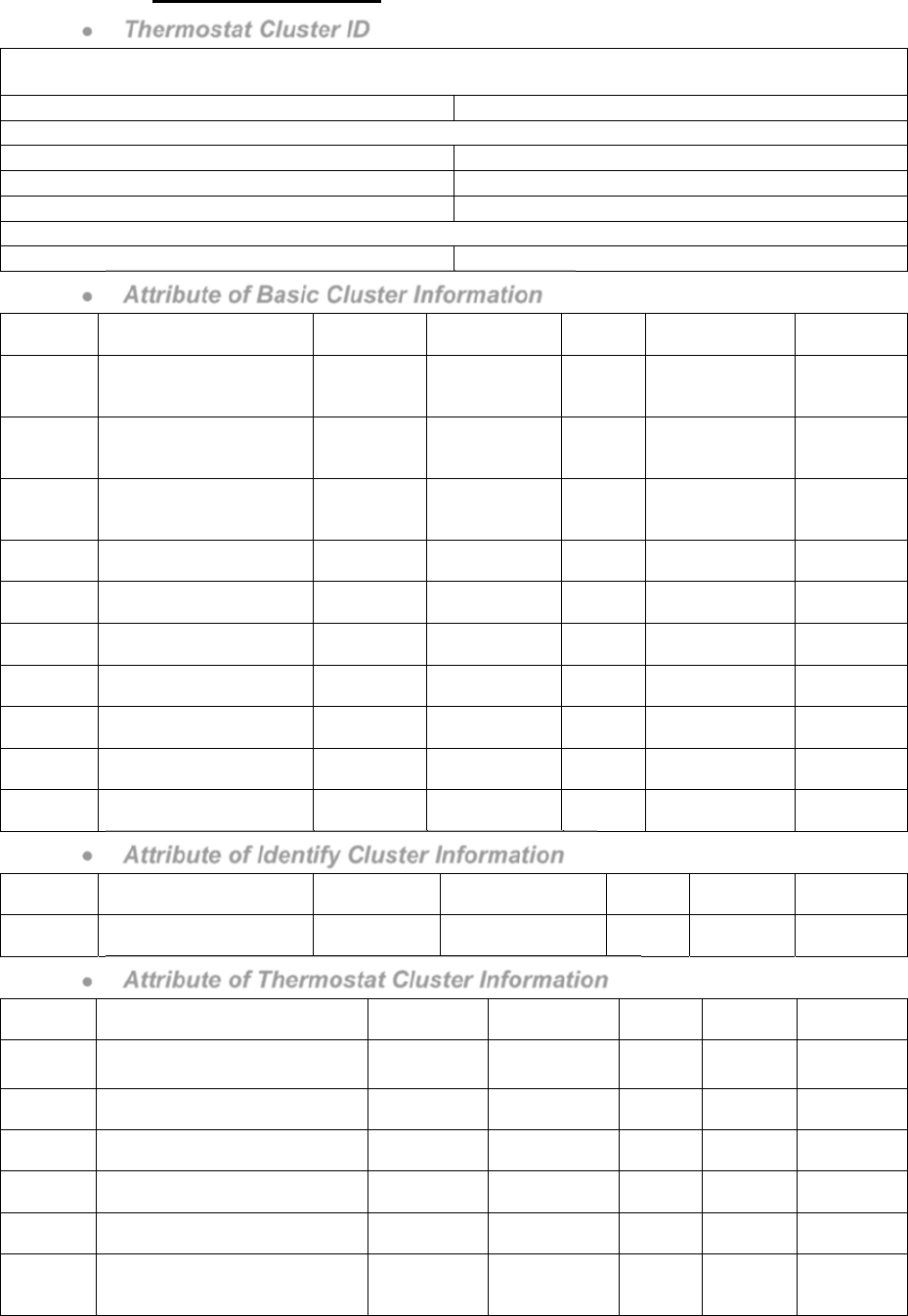
Thermostat Cluster ID
Device ID: ZCL_HA_DEVICEID_THERMOSTAT 0x0301
Endpoint: 0x01
Server Side Client Side
Mandatory
Basic (0x0000) Identify(0x0003)
Identify(0x0003)
HVAC THERMOSTAT (0x0201)
Optional
None None
Attribute of Basic Cluster Information
Identifier Name Type Range Access Default Mandatory
/ Optional
0x0000 ZCLVersion Unsigned
8-bit
integer
0x00 –0xff Read
only 0x01 M
0x0001 ApplicationVersion
Unsigned
8-bit
integer
0x00 –0xff Read
only 0x00 O
0x0003 HWVersion Unsigned
8-bit
integer
0x00 –0xff Read
only 0 O
0x0004 ManufacturerName Character
String 0 – 32 bytes Read
only
Climax
Technology O
0x0005 ModelIdentifier Character
String 0 – 32 bytes Read
only (Model Version) O
0x0006 DateCode Character
String 0 – 16 bytes Read
only
O
0x0007 PowerSource 8-bit 0x00 –0xff Read
only M
0x0010 LocationDescription Character
String 0 – 32 bytes Read /
Write O
0x0011 PhysicalEnvironment 8-bit 0x00 –0xff Read /
Write 0x00 O
0x0012 DeviceEnabled Boolean 0x00 –0x01 Read /
Write 0x01 M
Attribute of Identify Cluster Information
Identifier Name Type Range Access Default Mandatory
/ Optional
0x0000 IdentifyTime Unsigned
16-bit integer 0x00 –0xffff Read /
Write 0x0000 M
Attribute of Thermostat Cluster Information
Identifier Name Type Range Access Default Mandatory
/ Optional
0x0000 LOCAL_TEMPERATURE 16-bit 0x954d –
0x7fff
Read
only 0x0000 M
0x0003 MIN_HEAT_SETPOINT_LIMIT 16-bit 0x954d –
0x7fff
Read
only 0x01F4 O
0x0004 MAX_HEAT_SETPOINT_LIMIT 16-bit 0x954d –
0x7fff
Read
only 0x0DAC O
0x0005 MIN_COOL_SETPOINT_LIMIT 16-bit 0x954d –
0x7fff
Read
only 0x01F4 O
0x0006 MAX_COOL_SETPOINT_LIMIT 16-bit 0x954d –
0x7fff
Read
only 0x0DAC O
0x0011 OCCUPIED_COOLING_SETPOINT 16-bit
Min Cool
Setpoint Limit
– Max Cool
Read /
Write 0x0A28 M

6
Setpoint Limit
0x0012 OCCUPIED_HEATING_SETPOINT 16-bit
Min Heat
Setpoint Limit
–Max Heat
Setpoint Limit
Read /
Write 0x07D0 M
0x001B CTRL_SEQ_OF_OPER 8-bit
Enumeration 0x00 – 0x05 Read /
Write 0x04 M
0x001C SYSTEM MODE 8-bit
Enumeration 0x00 – 0x09 Read /
Write 0x04 M
Federal Communication Commission Interference Statement
This equipment has been tested and found to comply with the limits for a Class B
digital device, pursuant to Part 15 of the FCC Rules. These limits are designed to
provide reasonable protection against harmful interference in a residential
installation.
This equipment generates, uses and can radiate radio frequency energy and, if not
installed and used in accordance with the instructions, may cause harmful interference
to radio communications. However, there is no guarantee that interference will not
occur in a particular installation. If this equipment does cause harmful interference to
radio or television reception, which can be determined by turning the equipment off
and on, the user is encouraged to try to correct the interference by one of the following
measures:
. Reorient or relocate the receiving antenna.
. Increase the separation between the equipment and receiver.
. Connect the equipment into an outlet on a circuit different from that to which the
receiver is connected.
. Consult the dealer or an experienced radio/TV technician for help.
FCC Caution
: To assure continued compliance, any changes or modifications not
expressly approved by the party responsible for compliance could void the user's
authority to operate this equipment. (Example - use only shielded interface cables
when connecting to computer or peripheral devices).
FCC Radiation Exposure Statement
This equipment complies with FCC RF radiation exposure limits set forth for an
uncontrolled environment. This equipment should be installed and operated with
a minimum distance of 20 centimeters between the radiator and your body.
This transmitter must not be co-located or operating in conjunction with any other
antenna or transmitter.
The antennas used for this transmitter must be installed to provide a separation
distance of at least 20 cm from all persons and must not be co-located or operating in
conjunction with any other antenna or transmitter.
This device complies with Part 15 of the FCC Rules. Operation is subject to the
following two conditions:
(1) This device may not cause harmful interference, and
(2) This device must accept any interference received, including interference that may
cause undesired operation.
7