Climax Technology Co TRVZB Thermostatic Radiator Valve User Manual
Climax Technology Co Ltd Thermostatic Radiator Valve Users Manual
Users Manual
TRV-1ZBS Thermostatic Radiator Valve
Introduction
TRV-1ZBS is a ZigBee Radiator Valve designed to control the surrounding temperature by controlling the flow of
hot water of radiators in the ZigBee network, i.e. indoor room temperatures.
The Radiator Valve utilizes ZigBee technology for wireless signal transmission. ZigBee is a wireless
communication protocol that is reliable and has low power consumption and high transmission efficiency. Based
on the IEEE802.15.4 standard, ZigBee allows a large amount of devices to be included in a network and
coordinated for data exchange and signal transmission.
The Radiator Valve serves as an end device in the ZigBee network. It can be included in the ZigBee network to
transmit signal upon activation, it can be controlled manually or remotely.
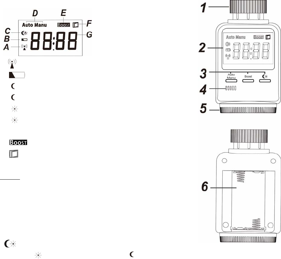
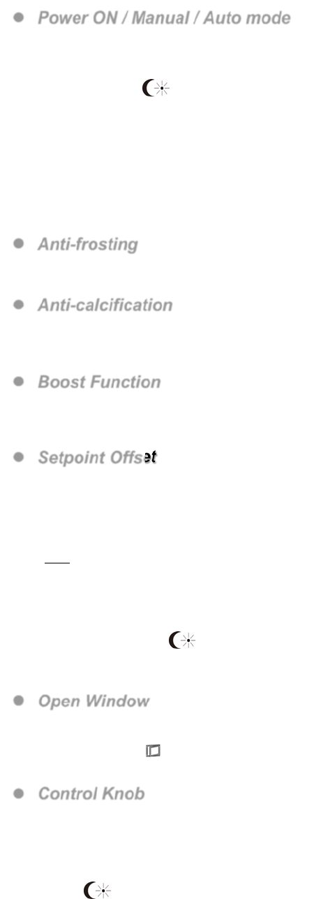
Parts Identification
1. Valve Cap
2. LCD Display
A. ON when device is already learned into Zig-Bee network.
B. Low Battery Indicator.
C. On: Device set to default temperature 17 °C.
Flash: Valve closing.
On: Device set to default temperature 21 °C.
Flash: Valve opening.
D. Auto / Manual Mode.
E. Boost function.
F. Open Window.
G. Temperature Indicator.
Others: InS: When power on device (also for learning period).
AdA: device motor working.
F1/F3: the valve is jammed, F2: no valve installed.
3. Function Buttons
-Manual/Auto: Enter Manual or Auto mode.
-Boost/ ZigBee: Speed up heating process/learn into ZigBee Network.
‐Press this button to instantly switch day and night temperatures.
Default day temperature: 21 °C, Default night temperature: 17 °C
4. Temperature Sensor
5. Control Knob
Adjust temperature manually.
6. Battery Compartment
The Radiator Valve is powered by two 1.5V AA alkaline batteries.
Features
Power ON / Manual / Auto mode
Power ON: When the Radiator Valve powers on, it’s motor starts working with LCD displaying InS, device is
ready for installation and start learning process. (see Installation for details)
Manual Mode: In the Manual mode, you can use the following functions:
- button: switch day/night temperatures instantly.
- Boost button: Speed up heating, learning device into Control Panel.
- Control Knob : Control temperature, set to ON (summer season mode) and OFF (winter
season mode)..
Auto Mode: The Auto mode is only available when device is learned with a control panel. After learning with
the Control Panel you can control and set the time schedule for the Radiator Valve
automatically through the control panel (please refer to your control panel manual for details).
In the Auto Mode, you can use the same functions as in Manual mode except the Control Knob
Set to ON and OFF function.
Anti-frosting
When the Radiator Valve detects a frosting hazard, it will automatically open the valve for hot water to flow in
order to maintain the temperature and to prevent further frosting.
Anti-calcification
The Radiator Valve will open and close the valve weekly to prevent calcification. During anti-calcification
process the LCD will display a CAL.
The default value for anti-calcification process is 23:00p.m every Saturday.
Boost Function
Press the Boost button to temporarily speed up heating process by further opening the valve. The boost
function lasts 5 minutes (LCD displays: 300 seconds countdown). If you wish to cancel boost function, press
the button again.
Setpoint Offset
The device is usually installed at the corner of the room and near the heating pipe. As a result its
temperature reading may deviate from room temperature at center of room. Use the Setpoint Offset
function to compensate the deviation.
To calculate setpoint offset, simply subtract room temperature with device temperature.
For example: If device temperature is 20°C and room temperature is 18°C, then setpoint offset = 18 – 20 =
-2°C.
After setpoint offset is applied, the device will operate according to adjusted temperature.
For example: If device temperature reading is 20°C, setpoint offset is -2°C, the device will operate using
18°C as actual reference.
To program Setpoint Offset:
1. Press and hold the button for 3 seconds to enter offset adjustment.
2. Rotate the Control Knob to desired offset temperature.
3. Press any key to finish and exit offset adjustment.
Open Window
If Radiator Valve detects indoor temperature drops rapidly by opening the window, the Radiator Valve will
activate Open Window function by partly closing the valve to reduce temperature setting for 15 minutes. The
LCD will display symbol, the device will check the temperature every minute. After 15 minutes, the
Radiator Valve will return to the set temperature with valve opening again, Open Window Function closes.
Control Knob
Rotate the Control Knob to adjust the temperature, rotate clockwise to reduce temperature and
anti-clockwise to increase the temperature. The adjustable temperature range is 5°C to 30°C. If you rotate
the Control Knob over 30°C to ON, after 1 minute, the Radiator Valve will open the valve completely, to
preserve battery power. If you rotate the Control Knob lower than 5°C to OFF, after 1 minute, the Radiator
Valve will close the valve completely. To disable ON/Off status please rotate the control knob or press
button.
ON: When turned to ON, the valve is opened completely. This function is used to preserver battery life
during summer, when heating is not required. Do not use this function in winter when heater is activated,
otherwise the room temperature will rise uncontrolled.
OFF: When turn to OFF, the valve is closed completely. This function is used when heater is activated but
heating is not required in a room with no occupants.
Key Lock Function
Press and hold both the Auto/Manual button and the button for 3 seconds to enable key lock function.
If successful the LCD will display the symbol. All keys and Control Knob actions will not respond. If
you wish to cancel key lock function, please press and hold both the Auto/Manual button and button for
3 seconds likewise.
Remote Control
After the Radiator Valve joins a ZigBee network, you can control the Radiator Valve via ZigBee network
coordinator or gateway. Please refer to your ZigBee coordinator/gateway manual for more information.
The following functions are only available for setting via ZigBee coordinator and gateway:
Schedule:
You can only program Schedule configuration via ZigBee network coordinator/gateway.
Schedule Setting: Up to 5 schedules can be programmed for every weekday with Mode, Setpoint and
Start time.
Schedule Control:
Normal - The Radiator Valve will execute programmed schedule setting accordingly.
No Schedule – The Radiator Valve will not execute any set schedule until it is set to Normal again.
Zig-Bee Network Setup and Installation
ZigBee Device Guideline
ZigBee is a wireless communication protocol that is reliable and has low power consumption and high
transmission efficiency. Based on IEEE802.15.4 standard, ZigBee allows a large amount of devices to be
included in a network and coordinated for data exchange and signal transmission.
Due to the fundamental structure of ZigBee network, ZigBee device will actively seek and join network after
powering on. Since performing a task in connecting network may consume some power, it is required to
follow the instructions to avoid draining battery of a ZigBee device.
- Ensure your ZigBee network router or coordinator is powered on before inserting battery into ZigBee device.
- Ensure the ZigBee network router or coordinator is powered on and within range while a ZigBee device is in
use.
- Do not remove a ZigBee device from the ZigBee network router or coordinator without removing the battery
from a ZigBee device.
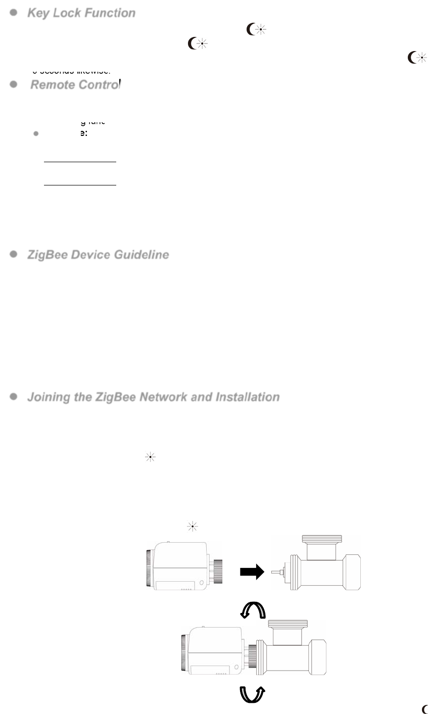
Joining the ZigBee Network and Installation
As a ZigBee device, the Radiator Valve needs to join a ZigBee network for user to control it remotely.
Joining ZigBee network should be performed together with installation at the same time. Please follow the
steps bellow to join the Radiator Valve into the ZigBee network.
1. Remove the Radiator Valve back cover and insert 2 AA Alkaline batteries to power up the Radiator Valve,
LCD will display InS and icon will flash to indicate Radiator Valve’s motor is working.
2. Press and hold the Boost button for 10 seconds, LCD will flash 888 to indicate release button to join
ZigBee network. Please make sure the permit-join feature on the router or coordinator of your ZigBee
network is enabled.
3. Wait for several seconds for the Radiator Valve to join ZigBee network. Please check the security system
control panel or CIE (Control and Indicating Equipment) to confirm if joining and registration is successful.
4. When the motor stops working and icon changes to steady on, attach the Valve cap to the pipe.
5. Rotating the Valve cap clockwise to tighten the Radiator Valve.
6. Press the Auto/Manual button, LCD displays AdA and valve motor starts working again, the icon will
flash. The device motor is measuring the distance to adjust the current temperature.
7. When the valve motor stops, the system will enter Manual mode with LCD displaying the default set
temperature 18.0°C, the installation is now complete.
8. After joining ZigBee network and completing installation, the ZigBee connection icon will appear on
LCD display.
9. After joining the ZigBee network, if the Radiator Valve loses connection to current ZigBee network, the
ZigBee connection icon will disappear after 10 minutes. Please check the ZigBee network condition and
Radiator Valve signal range to correct the situation.
Removing Device from ZigBee Network (Factory Reset)
To remove the Radiator Valve from current ZigBee network, the device must be put to Factory Reset to
complete device removal. Factory Reset function will clear the Radiator Valve of its stored setting and
information and prompt it to search for new ZigBee network.
Before removing device, make sure the Radiator Valve is within current ZigBee network signal range
1. Press and hold the function button for 10 seconds, then release the button to reset Radiator Valve.
2. Upon reset, the Radiator Valve will clear current ZigBee network setting and transmit signal to ZigBee
coordinator to remove itself from current ZigBee network. It will then actively search for available ZigBee
network again and join the network automatically.
Appendix(For developers only.)
Thermostat Cluster ID
Device ID: ZCL_HA_DEVICEID_THERMOSTAT 0x0301
Endpoint: 0x01
Server SideClient Side
Mandatory
Basic (0x0000)Identify(0x0003)
Power Config(0x0001) TIME(0x000A)
Identify(0x0003)
HVAC THERMOSTAT (0x0201)
Optional
NoneNone
Attribute of Basic Cluster Information
IdentifierNameTypeRangeAccessDefaultMandatory
/ Optional
0x0000
ZCLVersionUnsigned 8-bit
integer
0x00 –0xffRead only 0x01M
0x0001
ApplicationVersionUnsigned 8-bit
integer 0x00 –0xff
Read only 0x00O
0x0003
HWVersionUnsigned 8-bit
integer 0x00 –0xff
Read only 0O
0x0004
ManufacturerNameCharacter String
0 – 32 bytes Read only Climax
TechnologyO
0x0005
ModelIdentifierCharacter String
0 – 32 bytes Read only (Model
Version)O
0x0006
DateCodeCharacter String
0 – 16 bytes Read only
O
0x0007
PowerSource8-bit 0x00 –0xff Read only
M
0x0010
LocationDescriptionCharacter String
0 – 32 bytes Read /
Write O
0x0011
PhysicalEnvironment8-bit
0x00 –0xffRead /
Write 0x00O
0x0012
DeviceEnabledBoolean
0x00 –0x01 Read /
Write 0x01M
Attribute of Power Configuration Cluster Information
IdentifierNameTypeRangeAccessDefaultMandatory
/ Optional
0x0035BatteryAlarmMaskBitmap (8-bits) 0000 - 000x Read / Write 0000 0000O
Attribute of Identify Cluster Information
IdentifierNameType Range Access DefaultMandatory

/ Optional
0x0000IdentifyTimeUnsigned
16-bit integer 0x00 –0xffffRead /
Write 0x0000M
Attribute of Thermostat Cluster Information
IdentifierNameTypeRangeAccess DefaultMandatory
/ Optional
0x0000LOCAL_TEMPERATURE16-bit0x954d – 0x7fffRead
only 0x0000M
0x0003MIN_HEAT_SETPOINT_LI
MIT 16-bit0x954d – 0x7fffRead
only 0x01F4O
0x0004MAX_HEAT_SETPOINT_LI
MIT 16-bit0x954d – 0x7fffRead
only 0x0DACO
0x0005MIN_COOL_SETPOINT_LI
MIT 16-bit0x954d – 0x7fffRead
only 0x01F4O
0x0006MAX_COOL_SETPOINT_LI
MIT 16-bit0x954d – 0x7fffRead
only 0x0DACO
0x0011OCCUPIED_COOLING_SE
TPOINT16-bit
Min Cool Setpoint
Limit – Max Cool
Setpoint Limit
Read /
Write0x0A28M
0x0012OCCUPIED_HEATING_SET
POINT16-bit
Min Heat Setpoint
Limit – Max Heat
Setpoint Limit
Read /
Write0x07D0M
0x0019MIN_SETPOINT_DEAD_BA
ND 8-bit0x0A – 0x19Read /
Write 0x14O
0x001BCTRL_SEQ_OF_OPER8-bit
Enumeration 0x00 – 0x05Read /
Write 0x04M
0x001CSYSTEM MODE8-bit
Enumeration 0x00 – 0x09Read /
Write 0x04M
0x0020 START OF WEEK 8-bit
Enumeration 0x00 – 0x06 Read - O
0x0021NUMBER OF WEEKLY
TRANSITIONS
8-bit
unsigned 0x00 – 0xFF ReadN/A O
0x0022 NUMBER OF DAILY
TRANSITIONS
8-bit
unsigned 0x00 – 0xFF Read N/A O
0x0023 TEMPERATURE
SETPOINT HOLD
8-bit
enumeration 0x00- 0x01 Read/
Write 0x00 O
0x0024
TEMPERATURE
SETPOINT HOLD
DURATION
16-bit
unsigned 0xFFFF – 0x05A0 Read/
Write 0xFFFF O
0x0025 PROGRAMMING
OPERATION MODE 8-bit bitmap 00xxxxxx Read/
Write 00000000 O
Federal Communication Commission Interference Statement
ThisequipmenthasbeentestedandfoundtocomplywiththelimitsforaClassBdigital
device,pursuanttoPart15oftheFCCRules.Theselimitsaredesignedtoprovide
reasonableprotectionagainstharmfulinterferenceinaresidentialinstallation.
Thisequipmentgenerates,usesandcanradiateradiofrequencyenergyand,ifnotinstalled
andusedinaccordancewiththeinstructions,maycauseharmfulinterferencetoradio
communications.However,thereisnoguaranteethatinterferencewillnotoccurina
particularinstallation.Ifthisequipmentdoescauseharmfulinterferencetoradioor
televisionreception,whichcanbedeterminedbyturningtheequipmentoffandon,the
userisencouragedtotrytocorrecttheinterferencebyoneofthefollowingmeasures:
.Reorientorrelocatethereceivingantenna.
.Increasetheseparationbetweentheequipmentandreceiver.
.Connecttheequipmentintoanoutletonacircuitdifferentfromthattowhichthereceiver
isconnected.
.Consultthedealeroranexperiencedradio/TVtechnicianforhelp.
FCCCaution:Toassurecontinuedcompliance,anychangesormodificationsnotexpressly
approvedbythepartyresponsibleforcompliancecouldvoidtheuser'sauthoritytooperate
thisequipment.(Example‐useonlyshieldedinterfacecableswhenconnectingtocomputer
orperipheraldevices).
FCCRadiationExposureStatement
ThisequipmentcomplieswithFCCRFradiationexposurelimitssetforthforanuncontrolled
environment.Thisequipmentshouldbeinstalledandoperatedwithaminimumdistance
of20centimetersbetweentheradiatorandyourbody.
Thistransmittermustnotbeco‐locatedoroperatinginconjunctionwithanyotherantenna
ortransmitter.
Theantennasusedforthistransmittermustbeinstalledtoprovideaseparationdistanceof
atleast20cmfromallpersonsandmustnotbeco‐locatedoroperatinginconjunctionwith
anyotherantennaortransmitter.
ThisdevicecomplieswithPart15oftheFCCRules.Operationissubjecttothefollowingtwo
conditions:
(1)Thisdevicemaynotcauseharmfulinterference,and
(2)Thisdevicemustacceptanyinterferencereceived,includinginterferencethatmaycause
undesiredoperation.