Climax Technology Co WTGS THE WRIST TRANSMITTER User Manual User s Manual
Climax Technology Co Ltd THE WRIST TRANSMITTER User s Manual
UserManual.wiki
>
Climax Technology Co
>
WTGS User Manual
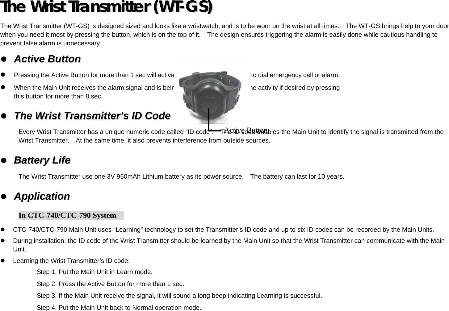
USERS MANUAL
Navigation menu
Upload a User Manual
Namespaces
Wiki Guide
HTML
PDF
Info
Views
User Manual
Discussion / Help
Navigation