Climax Technology Co Z1 Smart Home Alarm System User Manual
Climax Technology Co Ltd Smart Home Alarm System Users Manual
UserManual.wiki
>
Climax Technology Co
>
Z1 User Manual
Users Manual
Navigation menu
Upload a User Manual
Namespaces
Wiki Guide
HTML
PDF
Info
Views
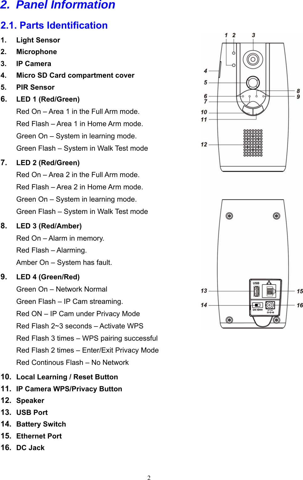
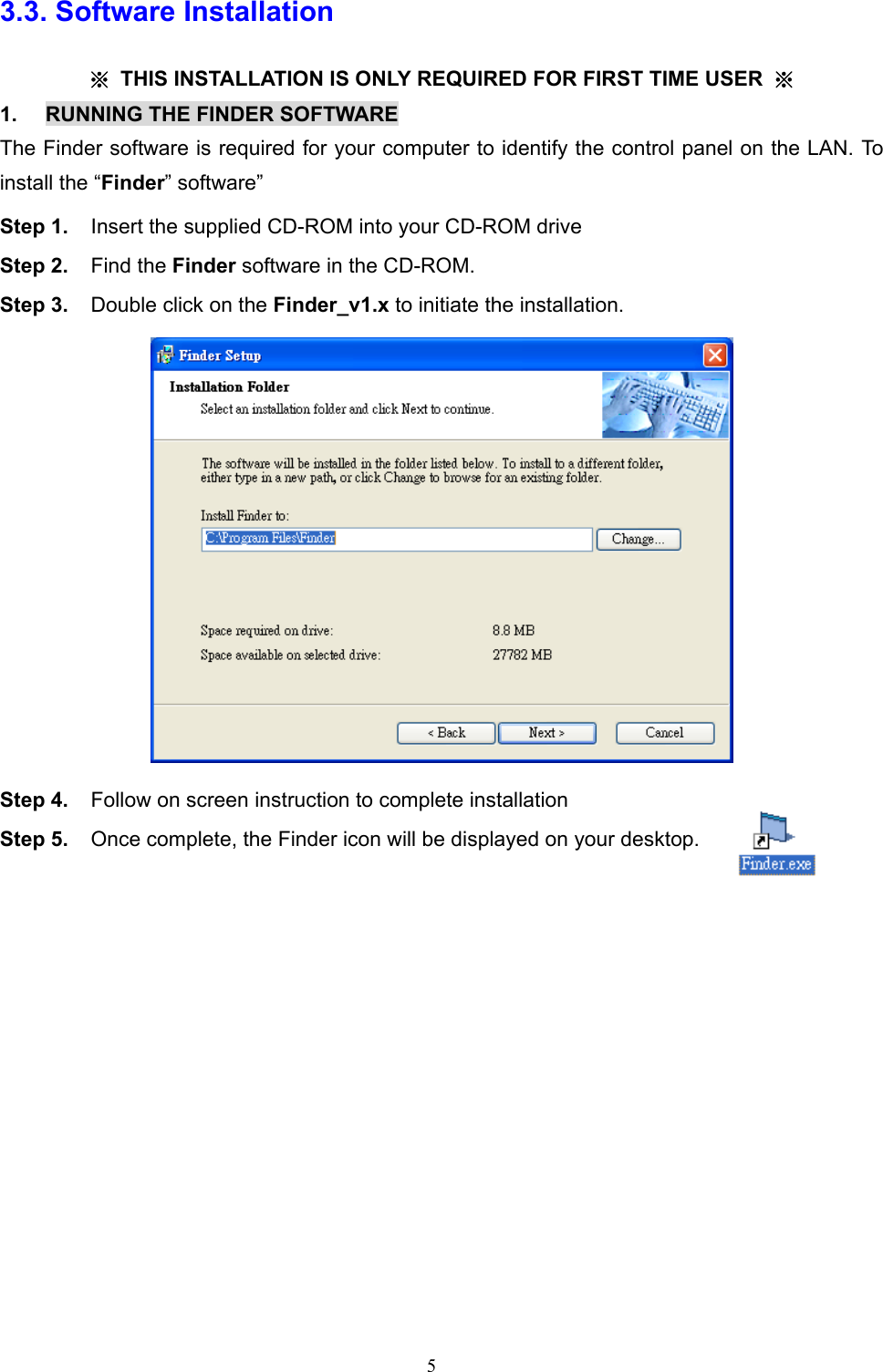
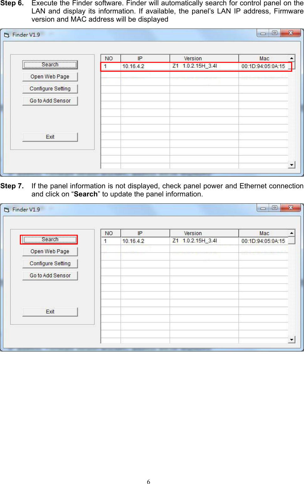
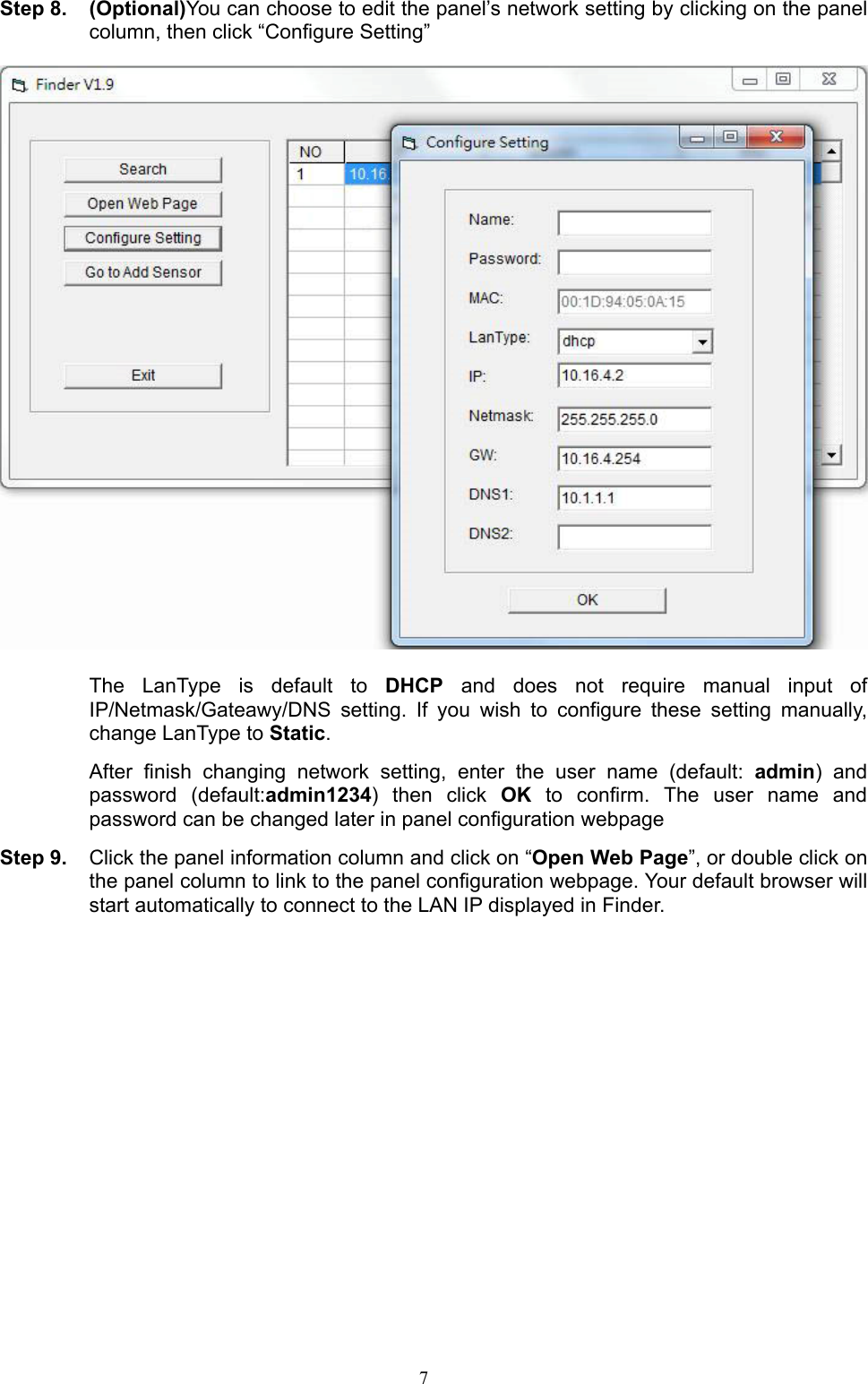
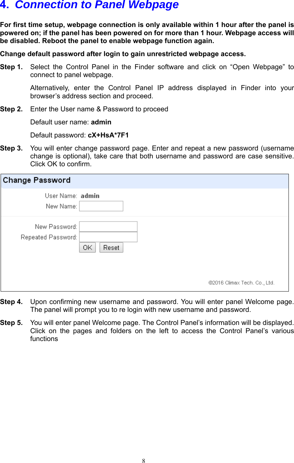
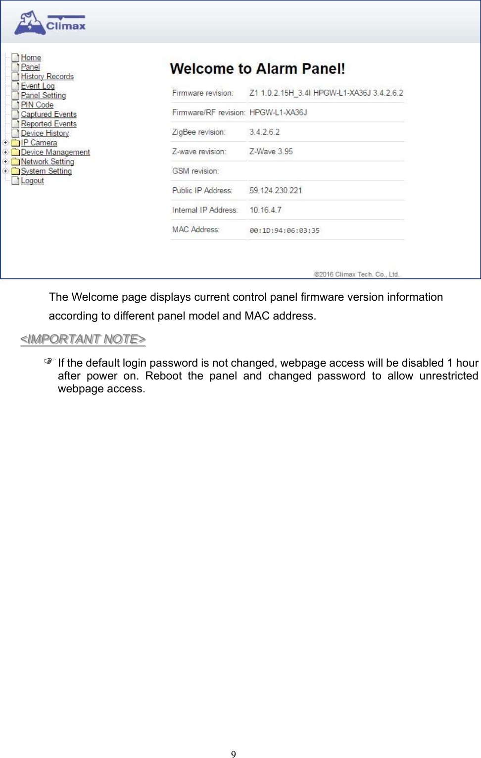
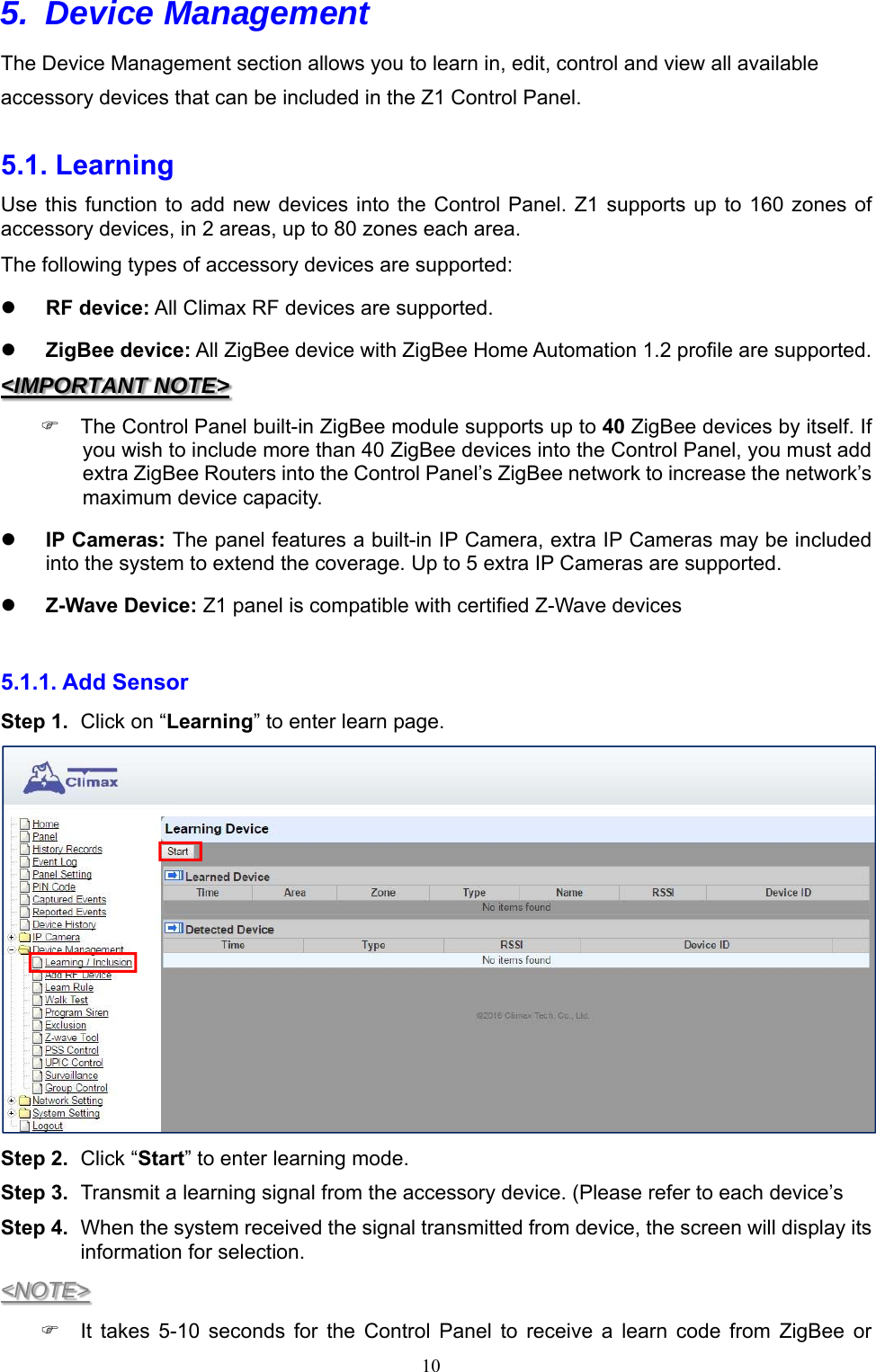
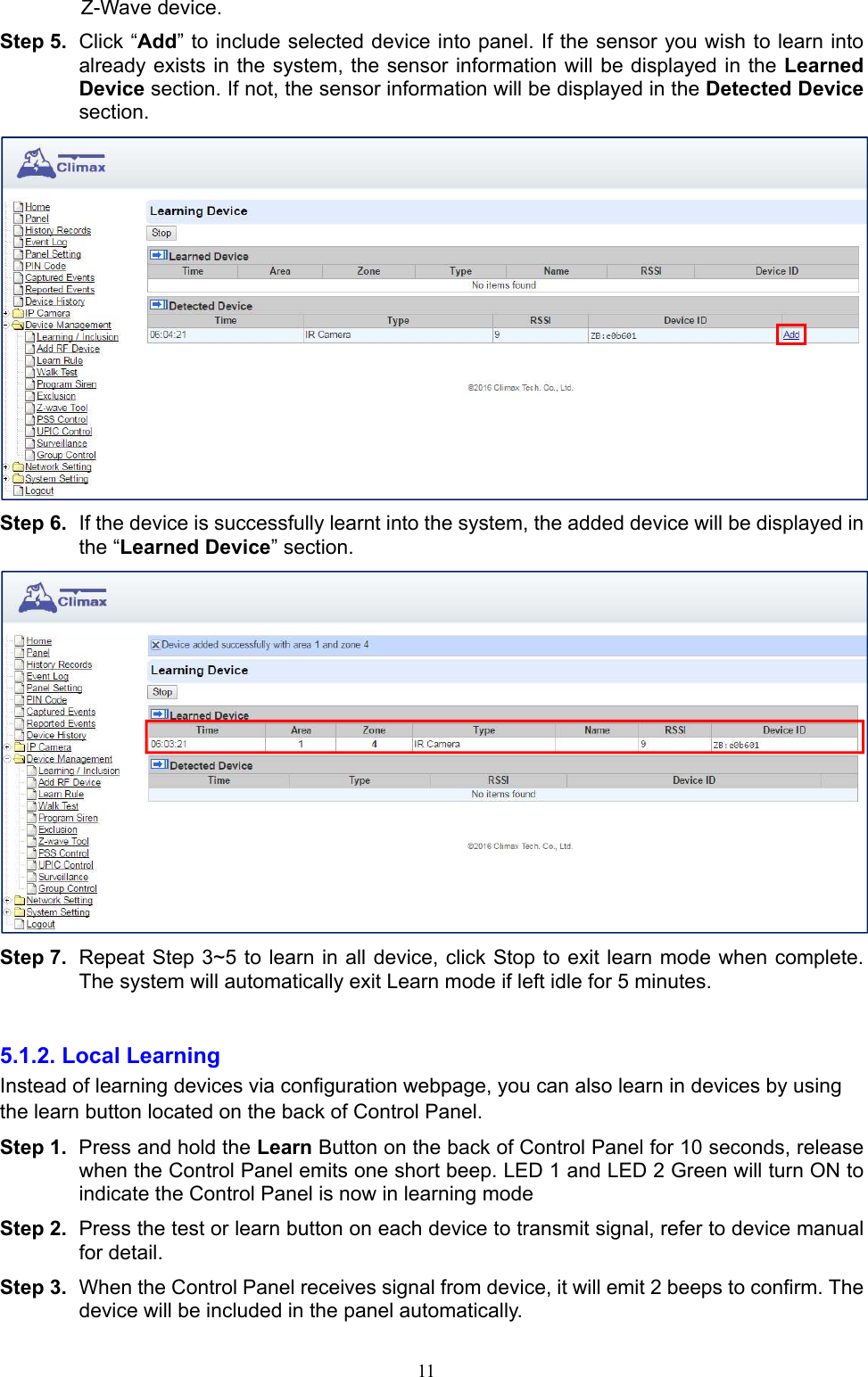
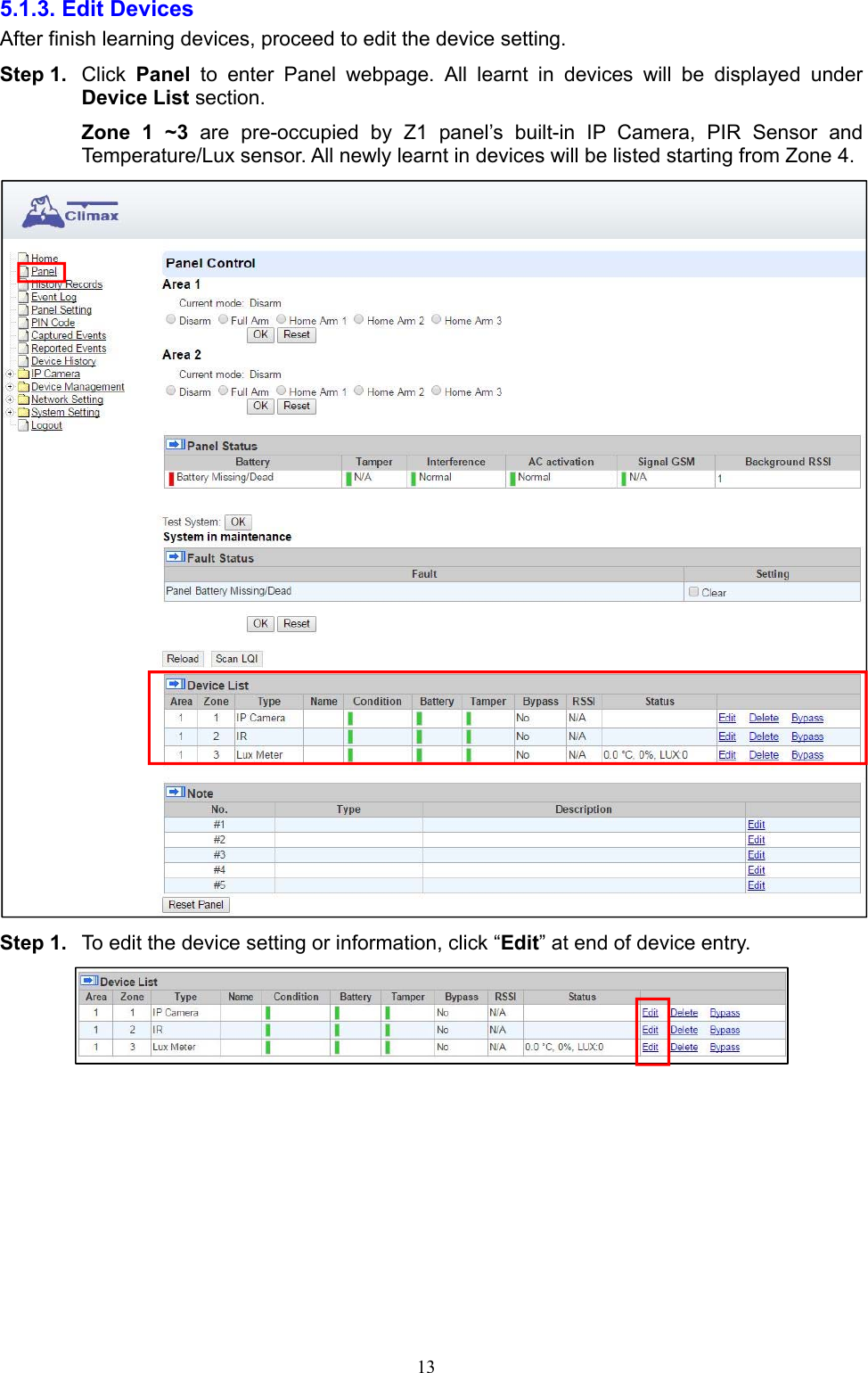
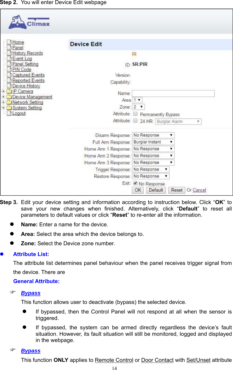
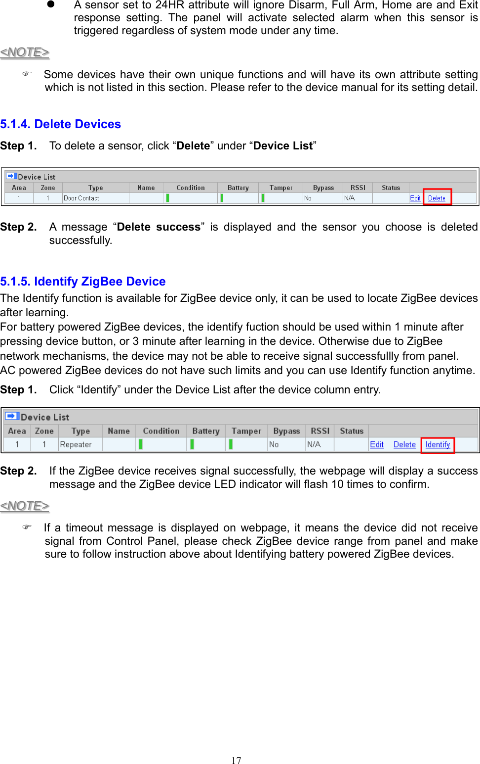
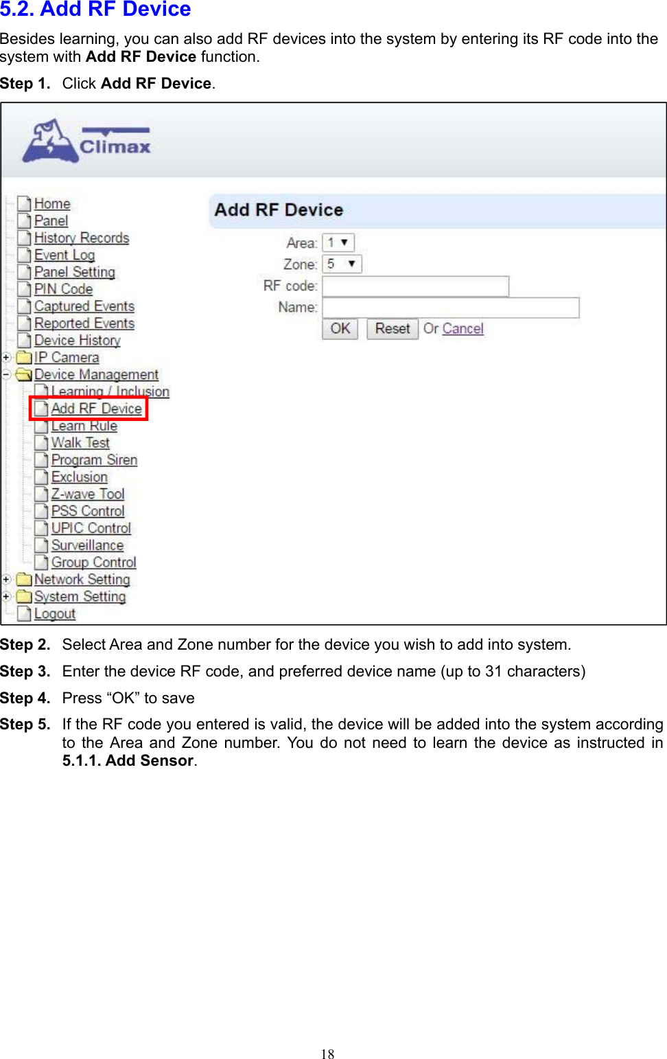
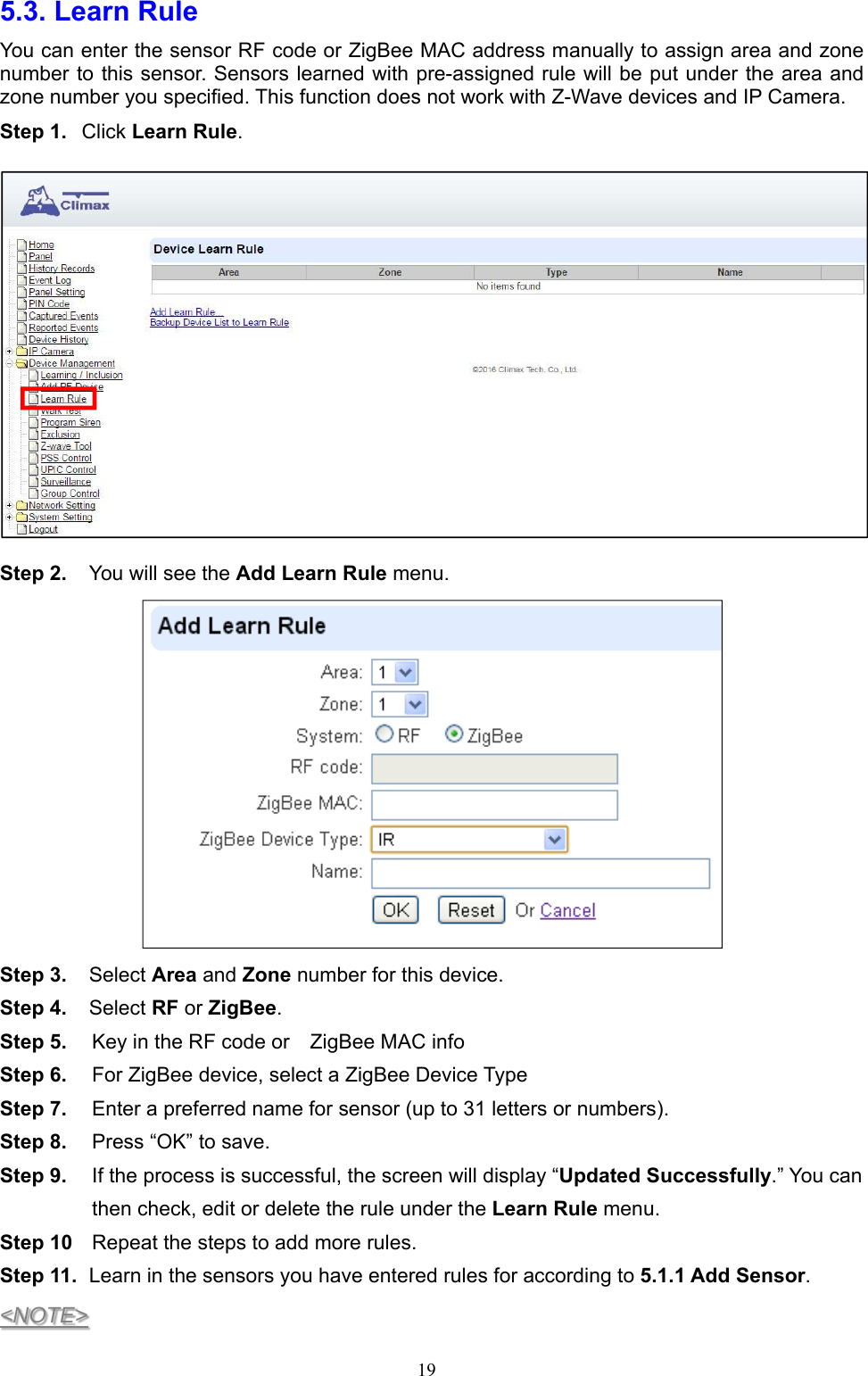
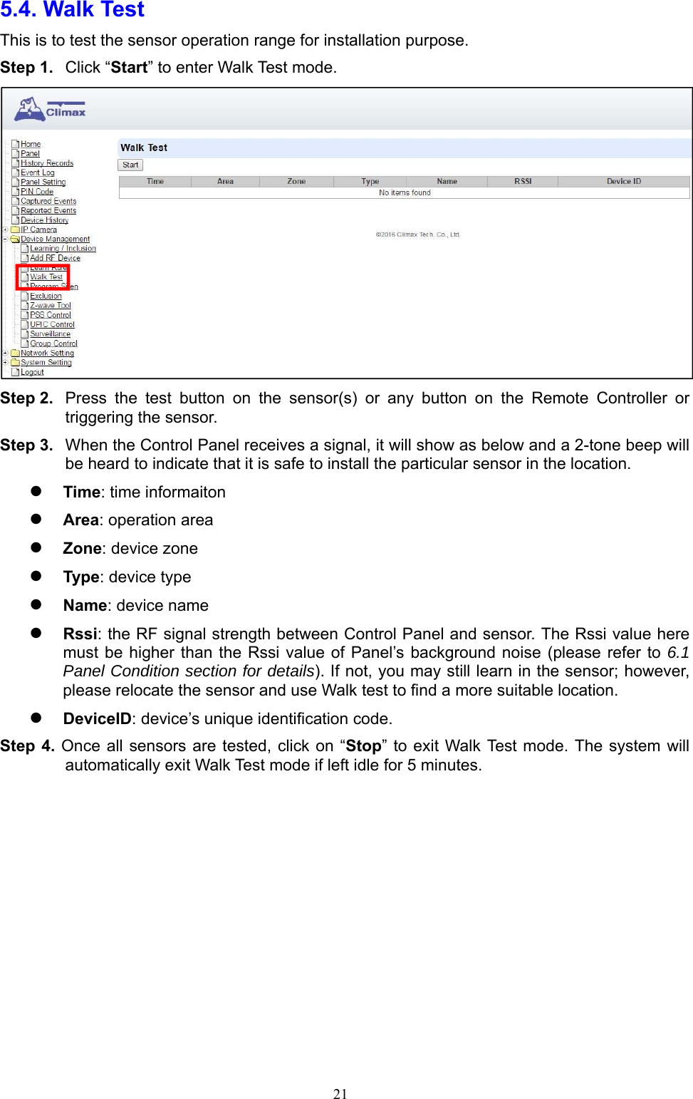
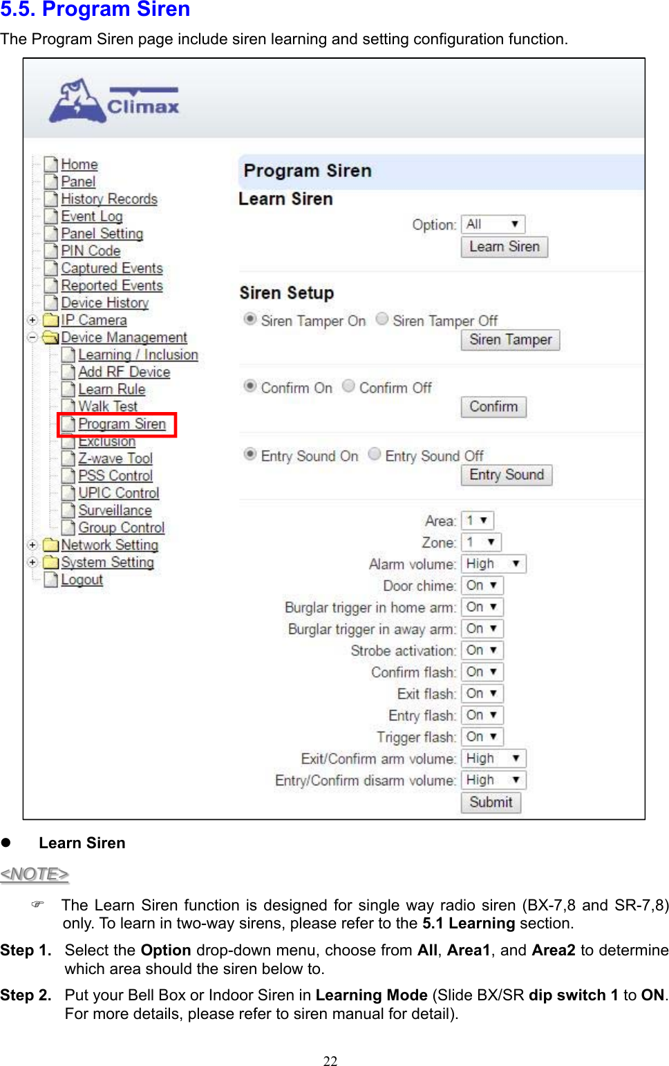
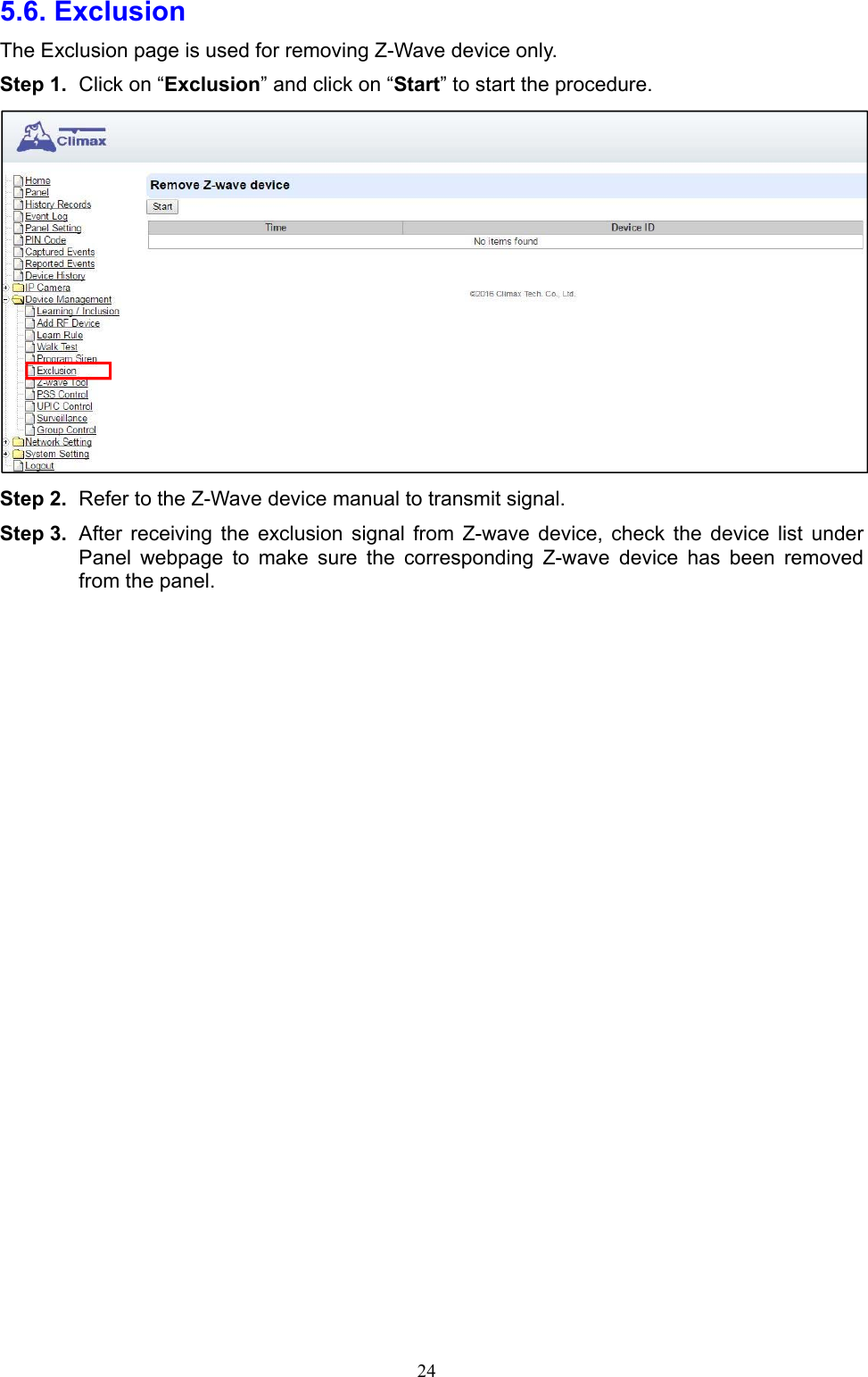
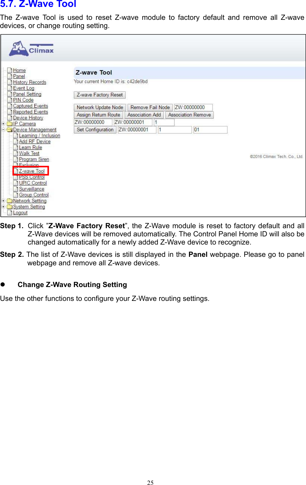
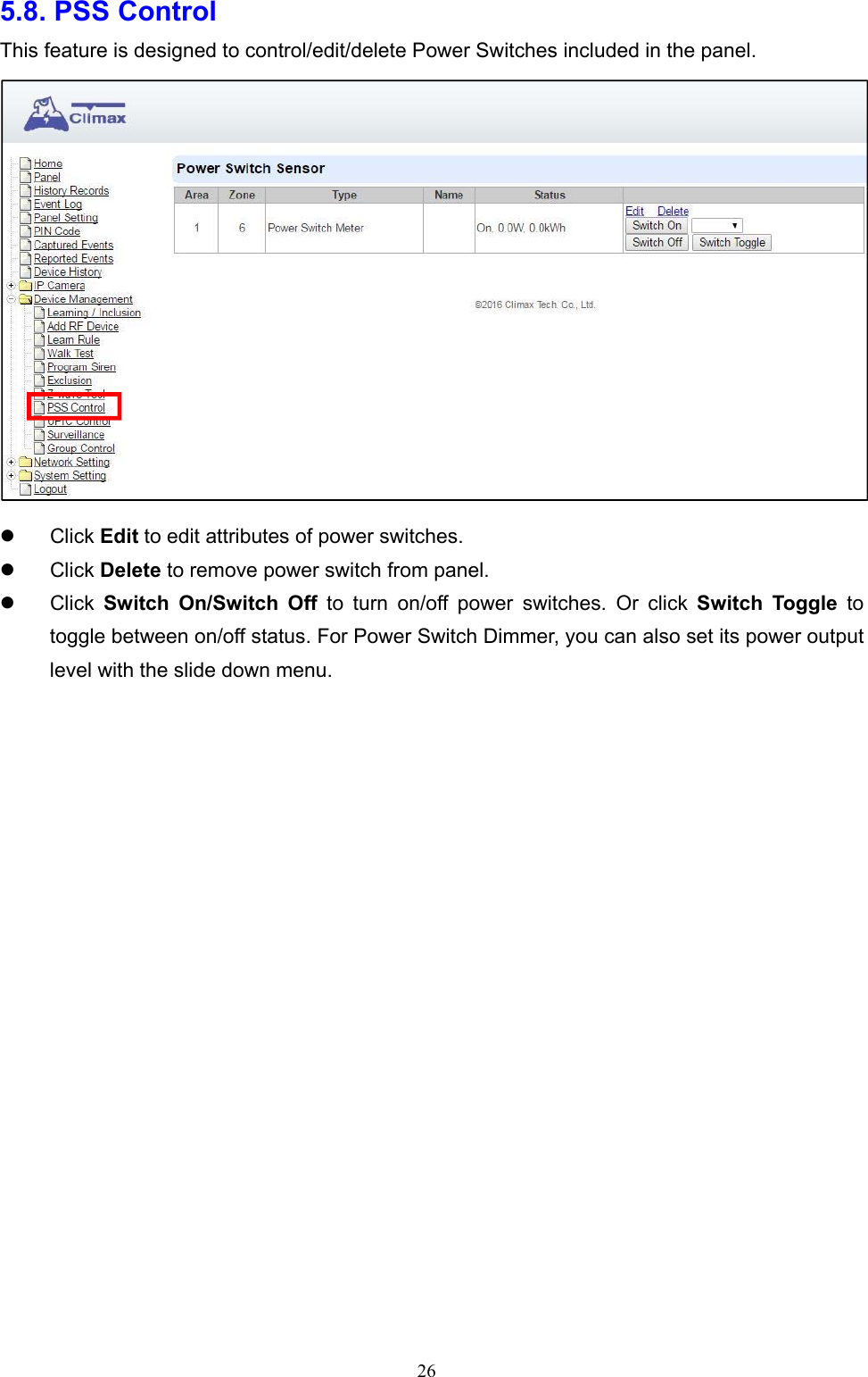
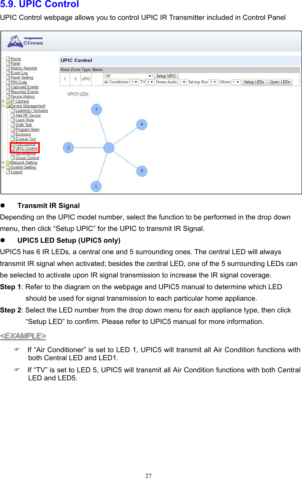
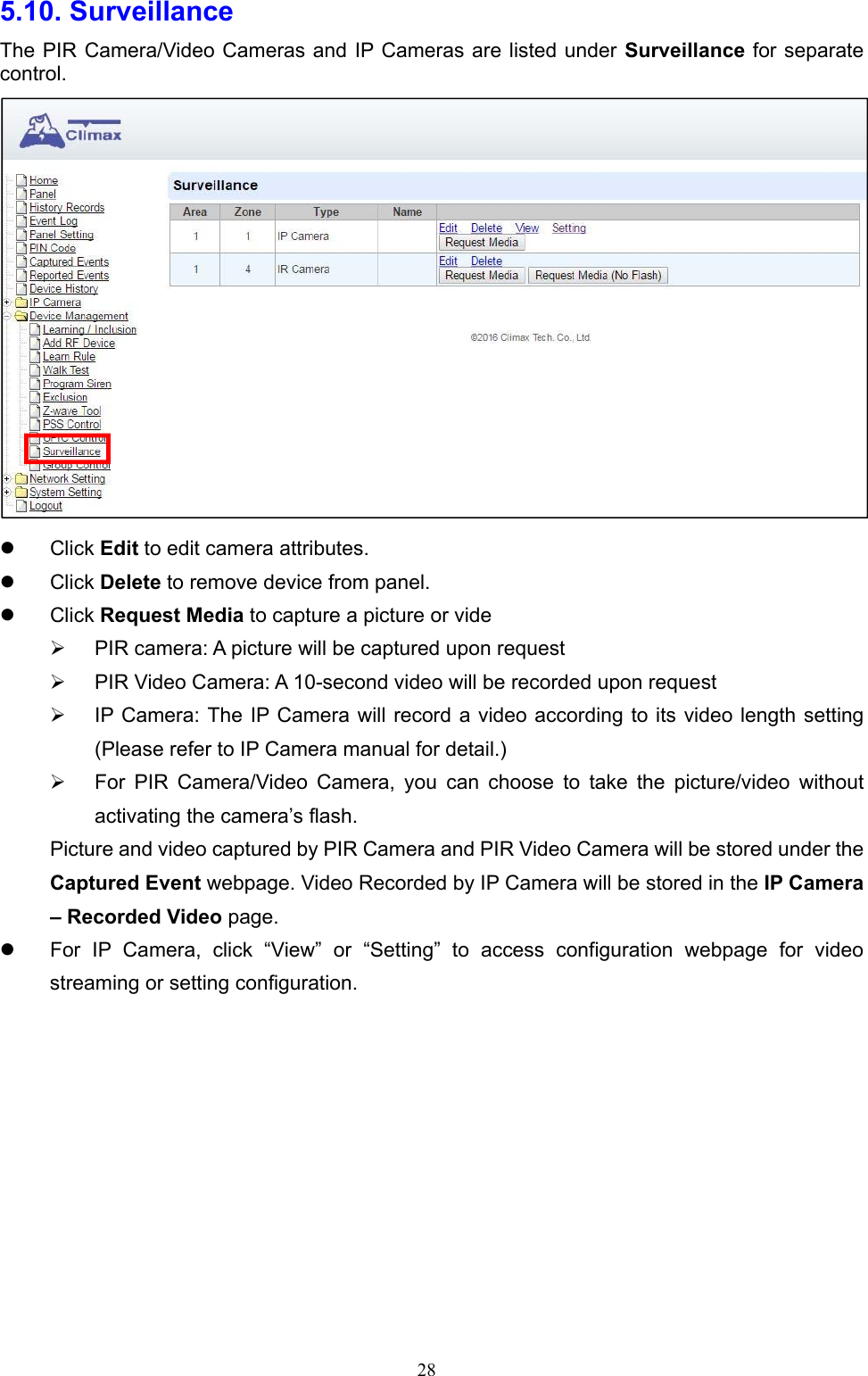
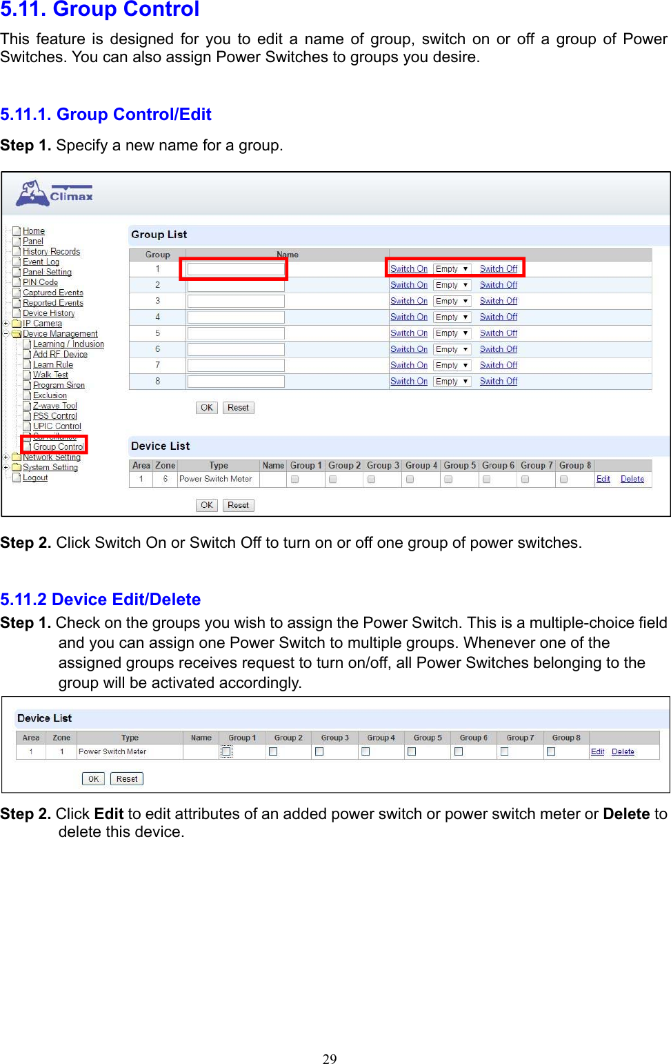
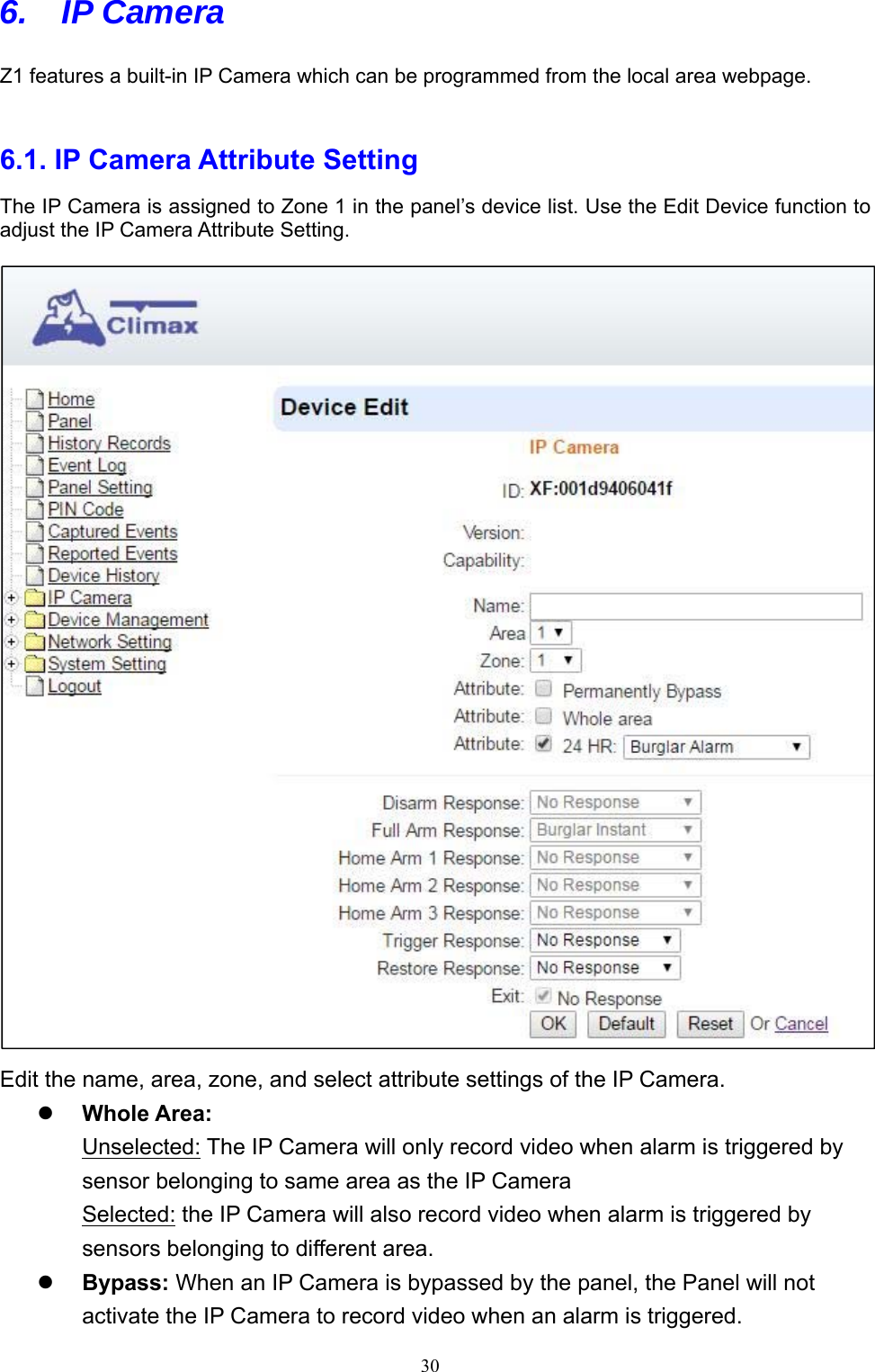
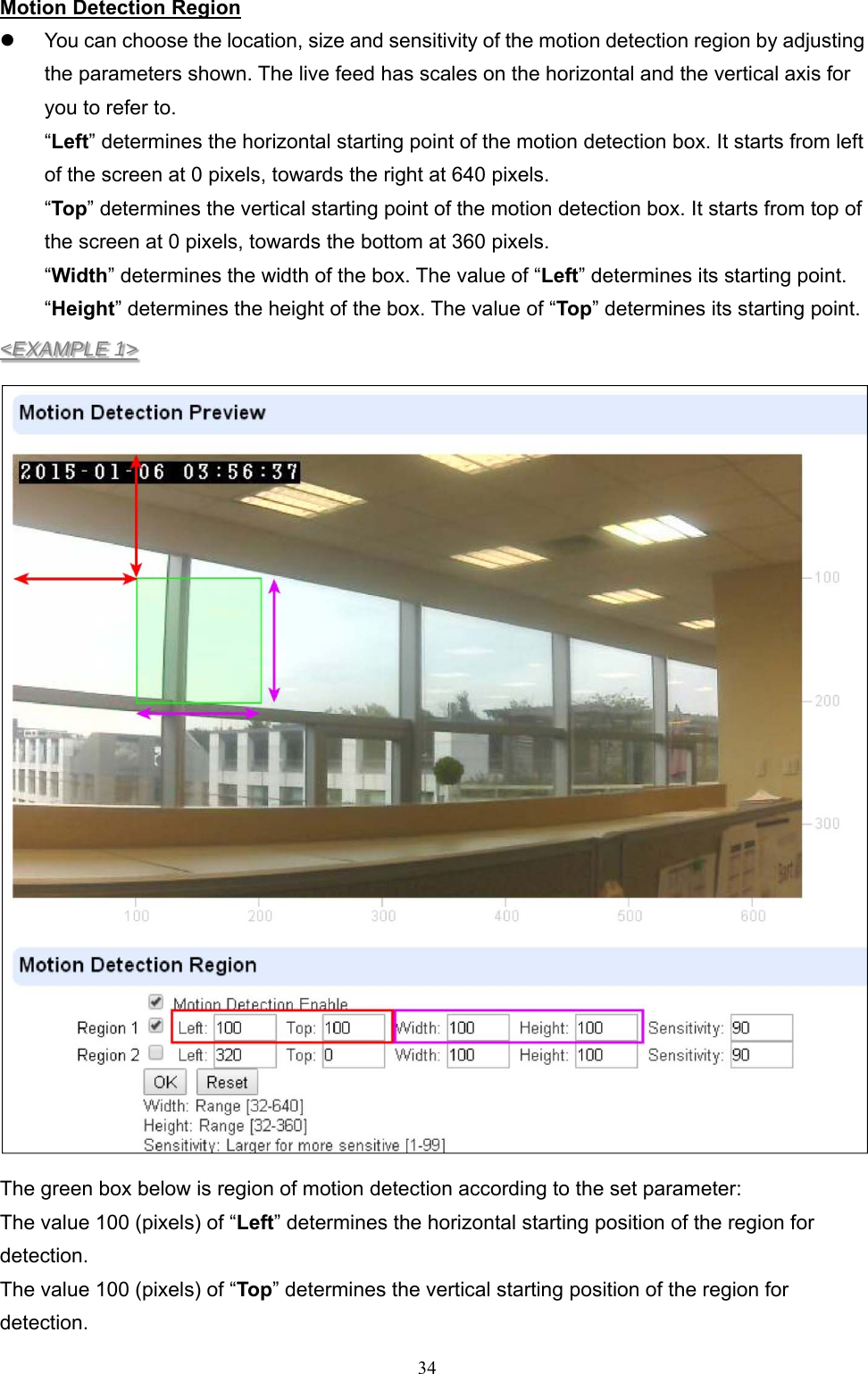
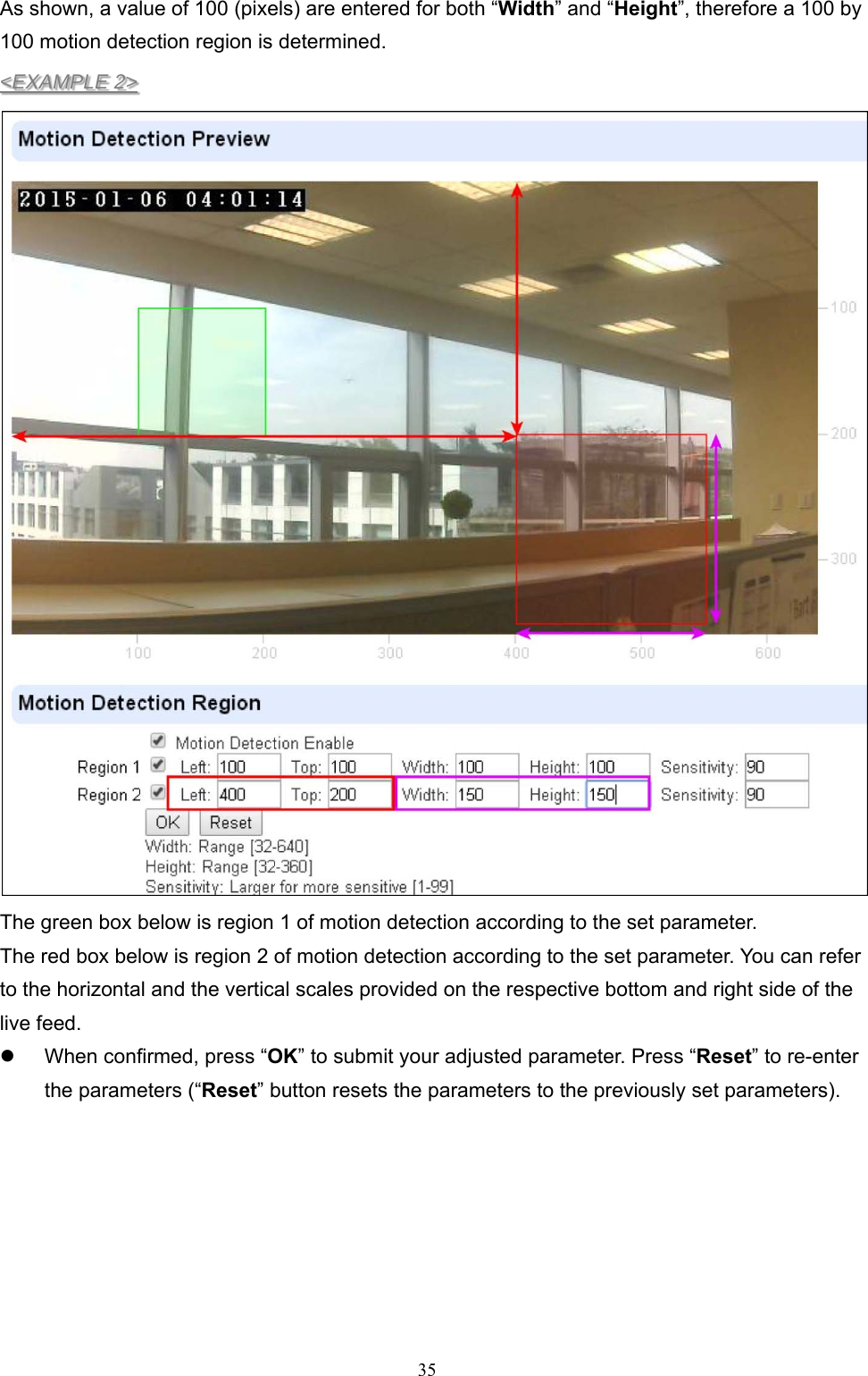
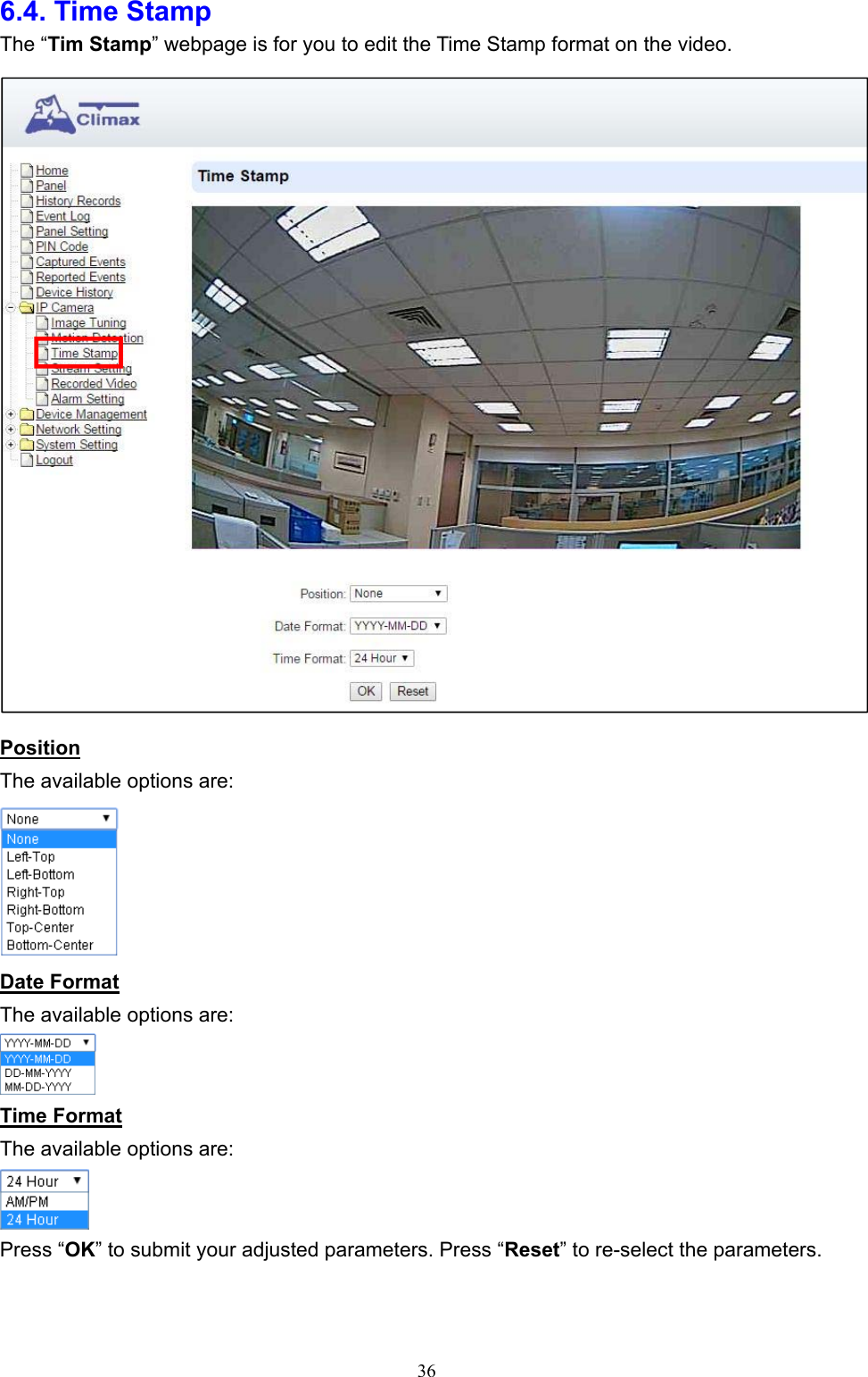
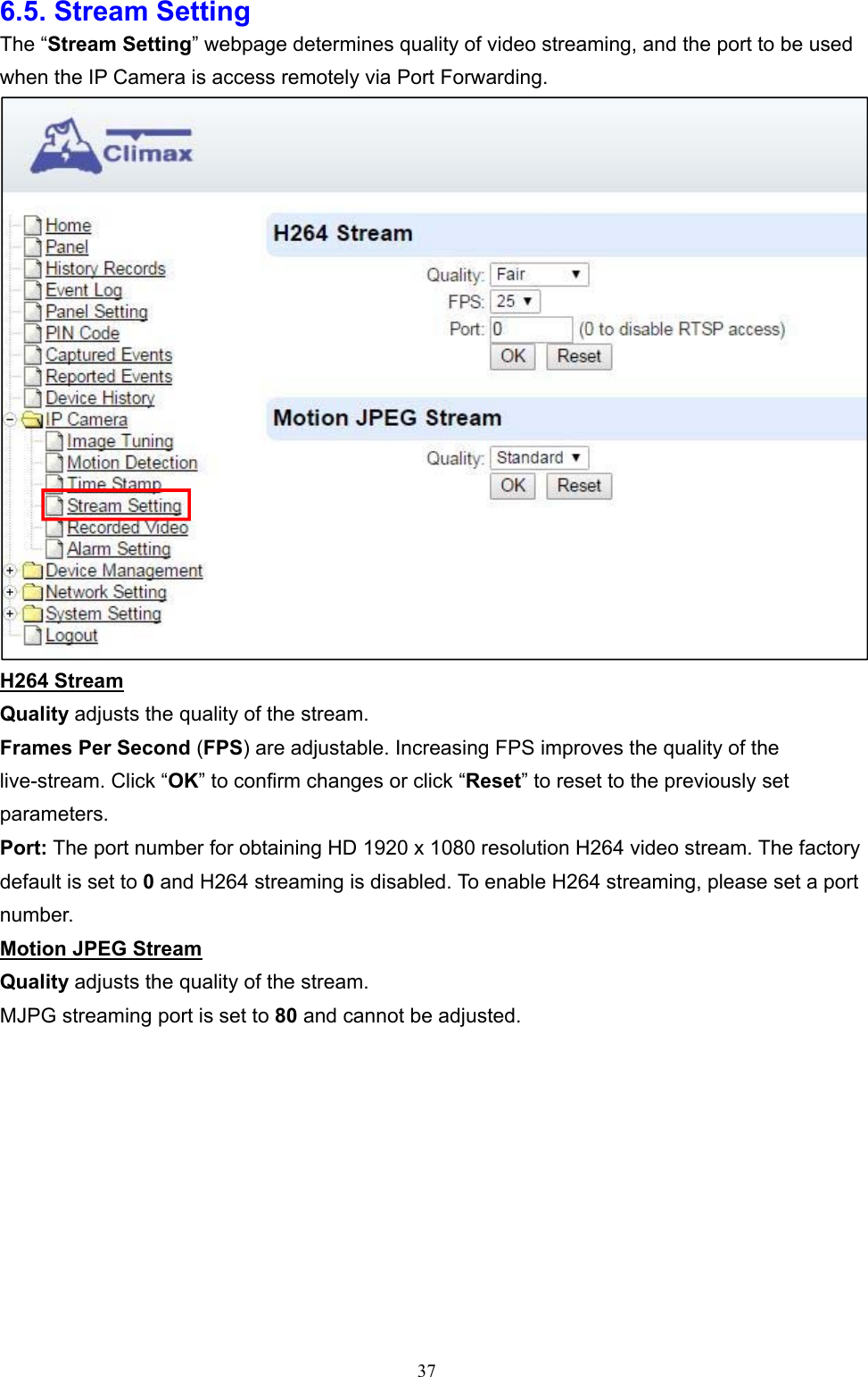
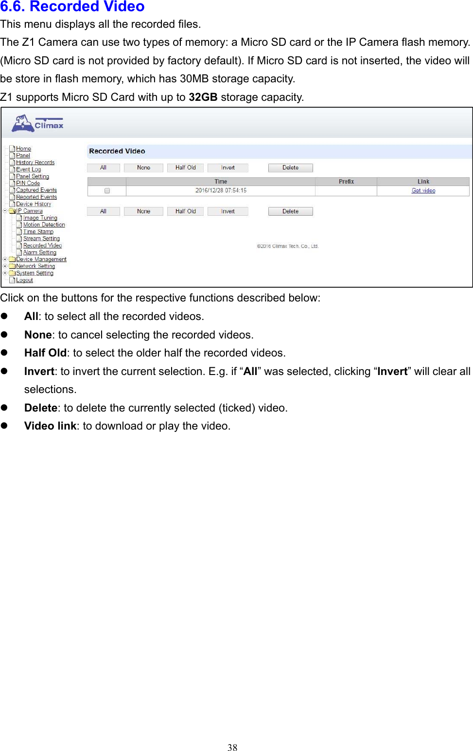
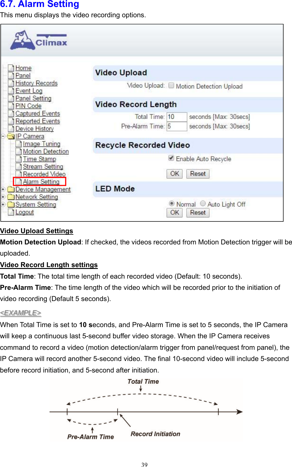
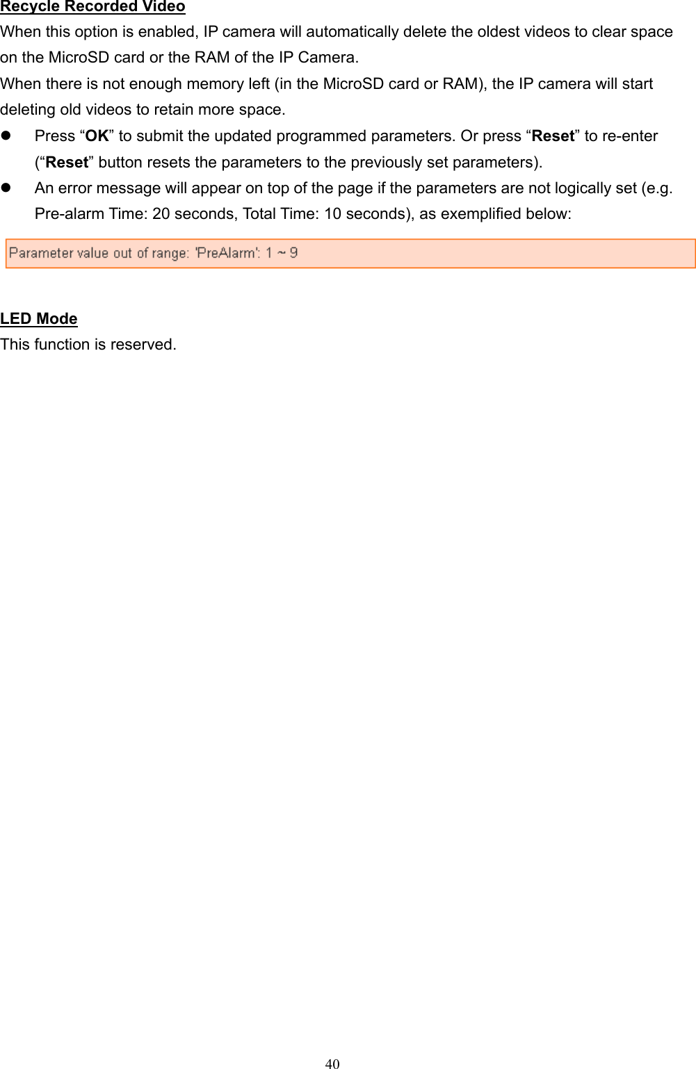
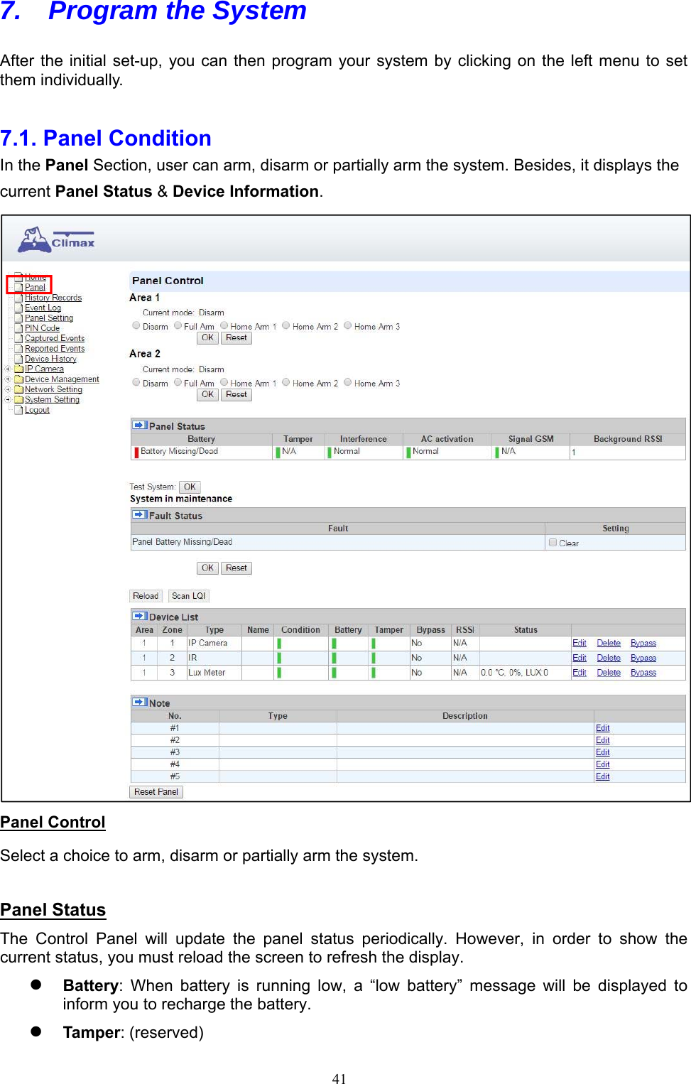
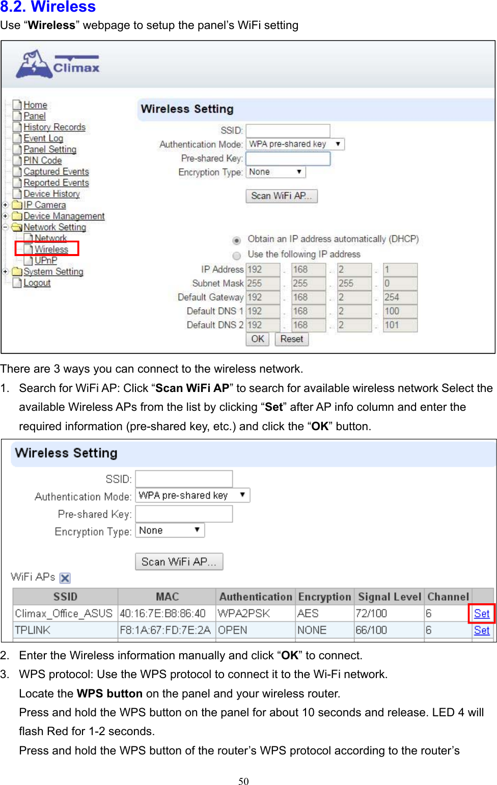
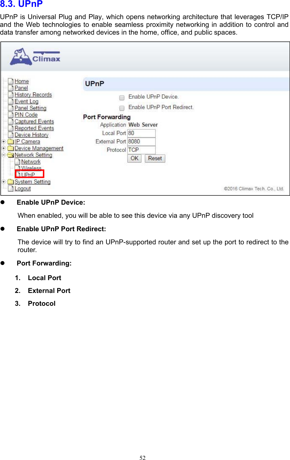
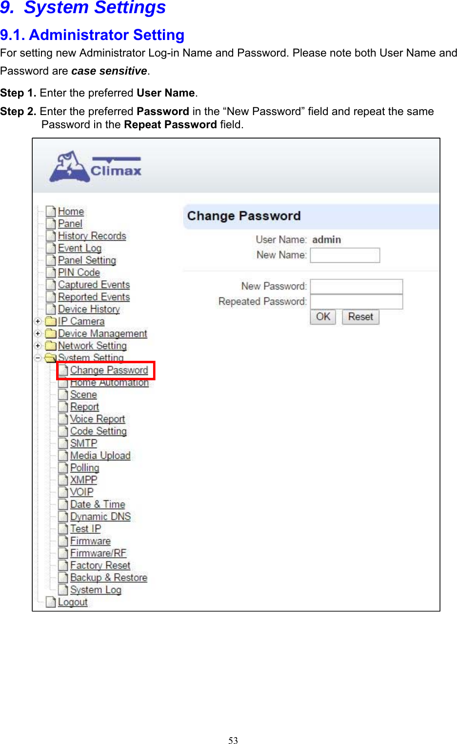
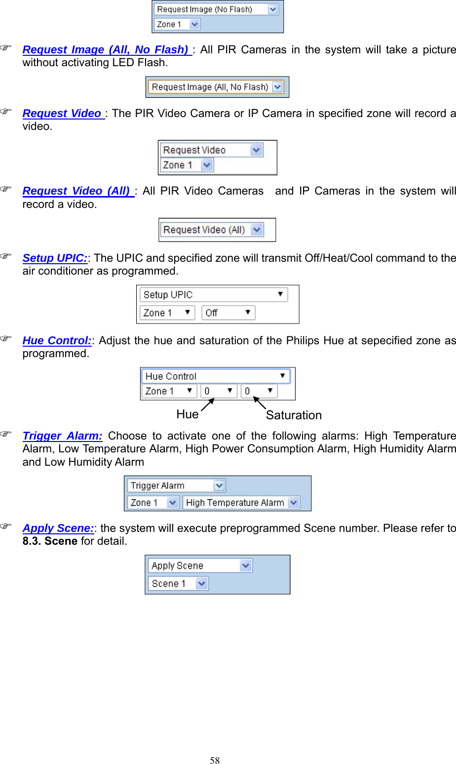
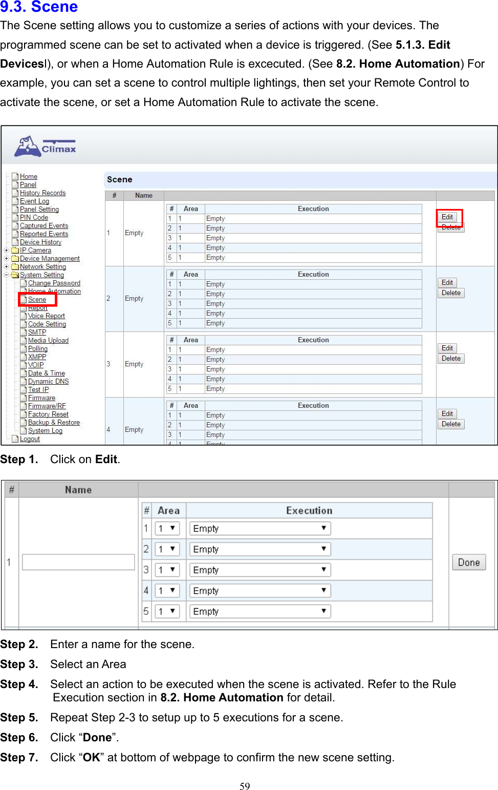
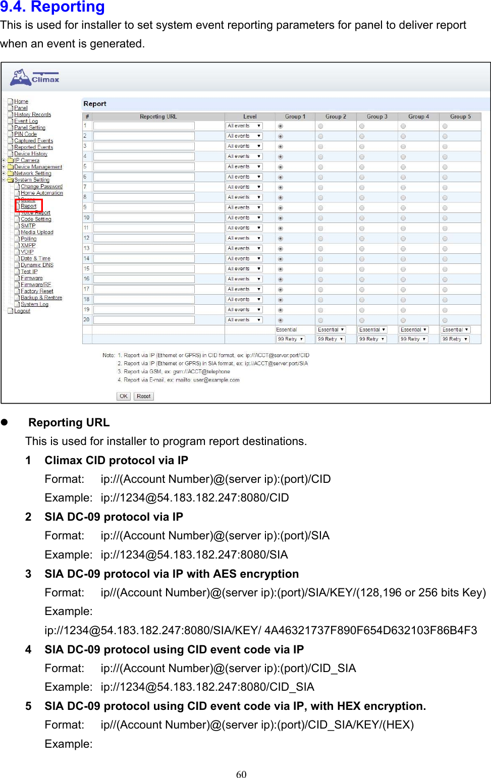
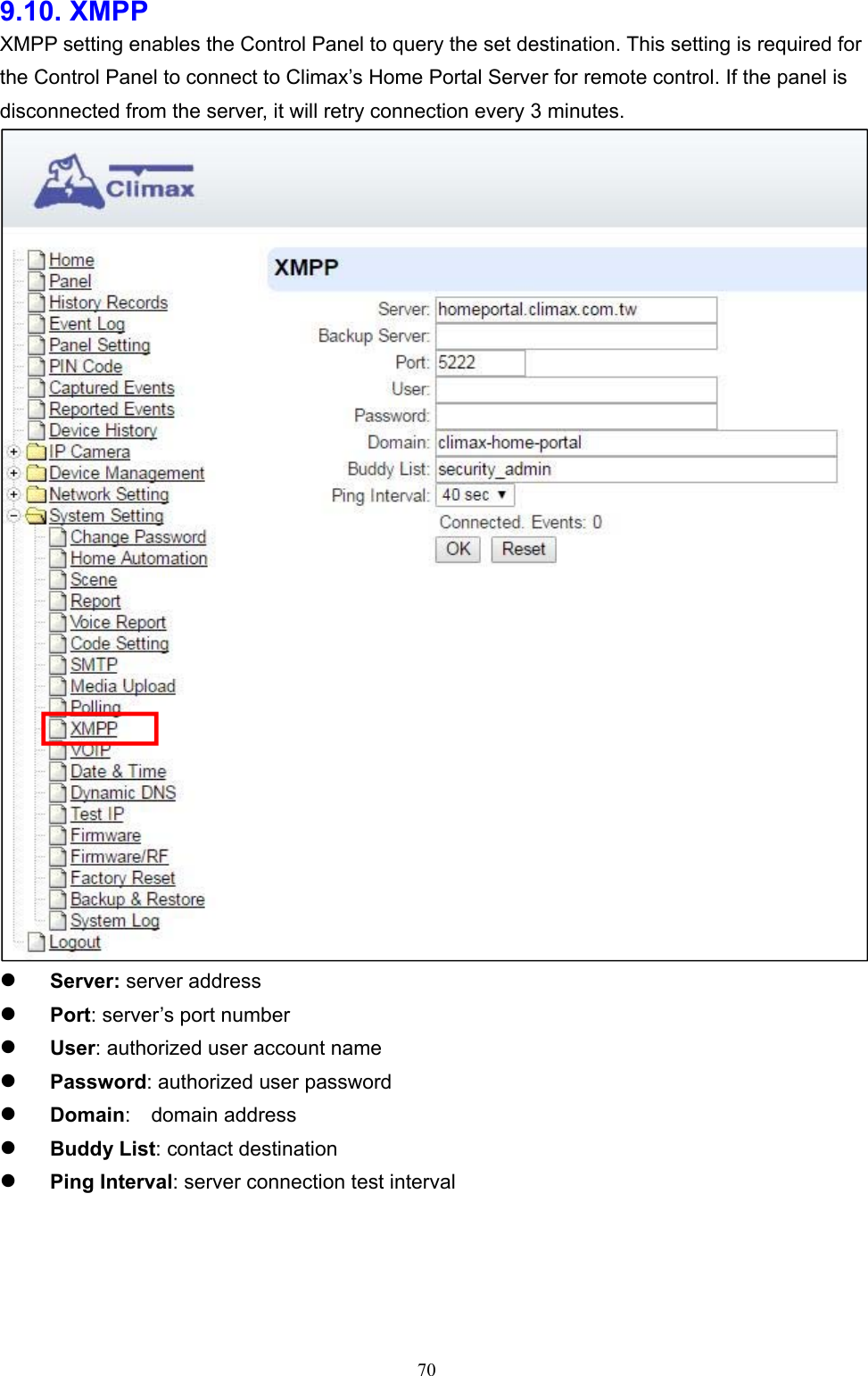
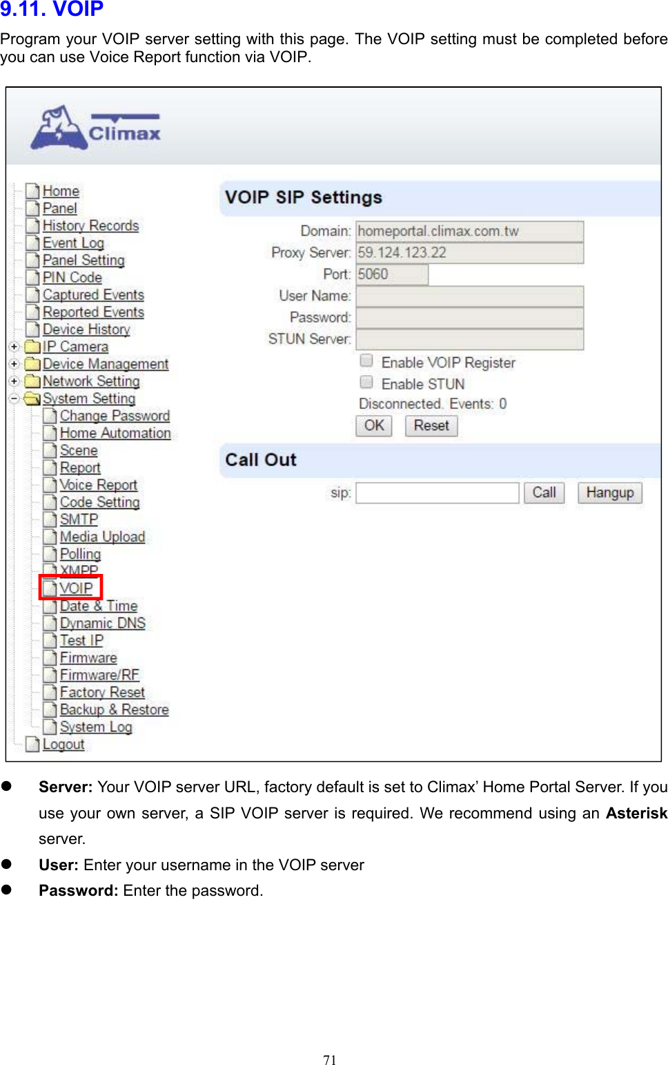
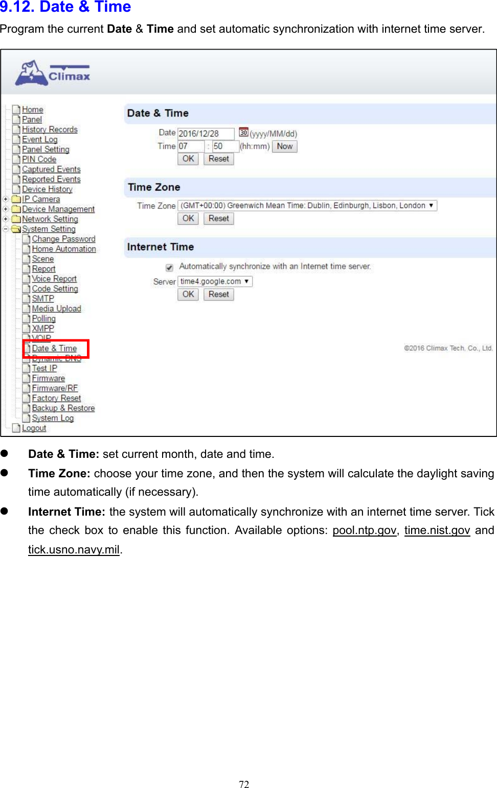
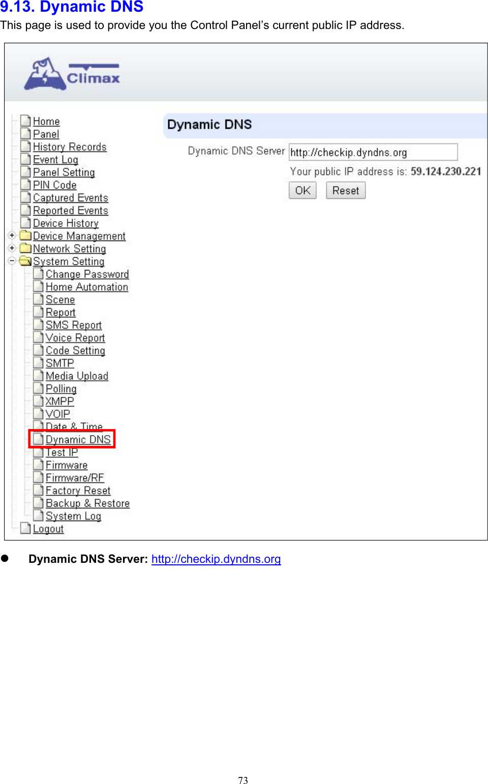
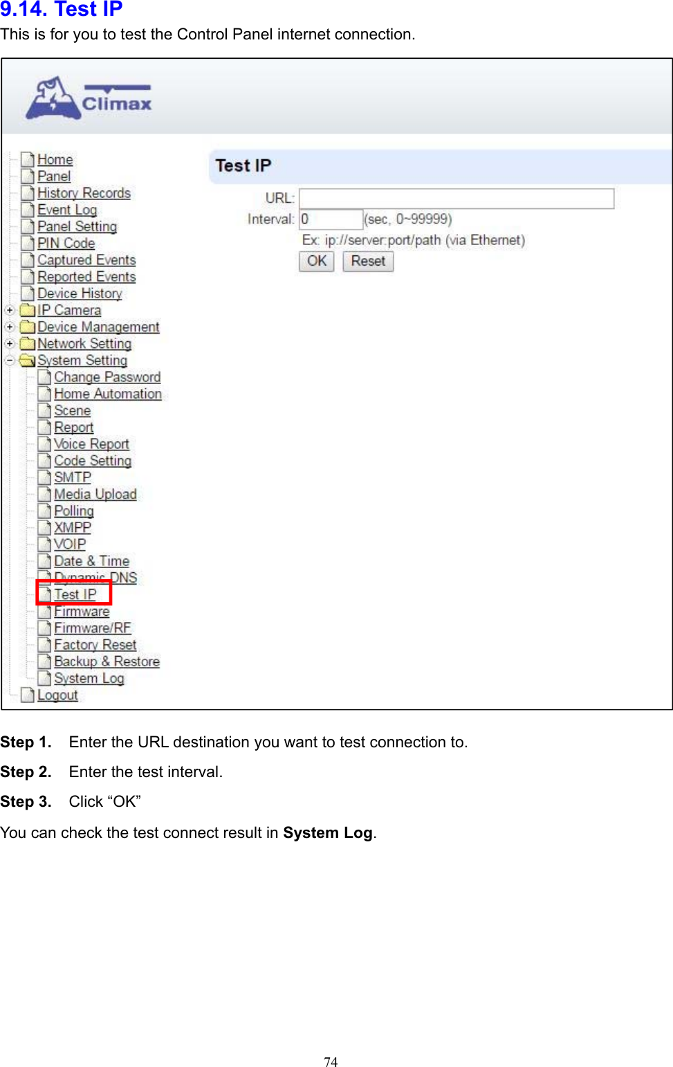
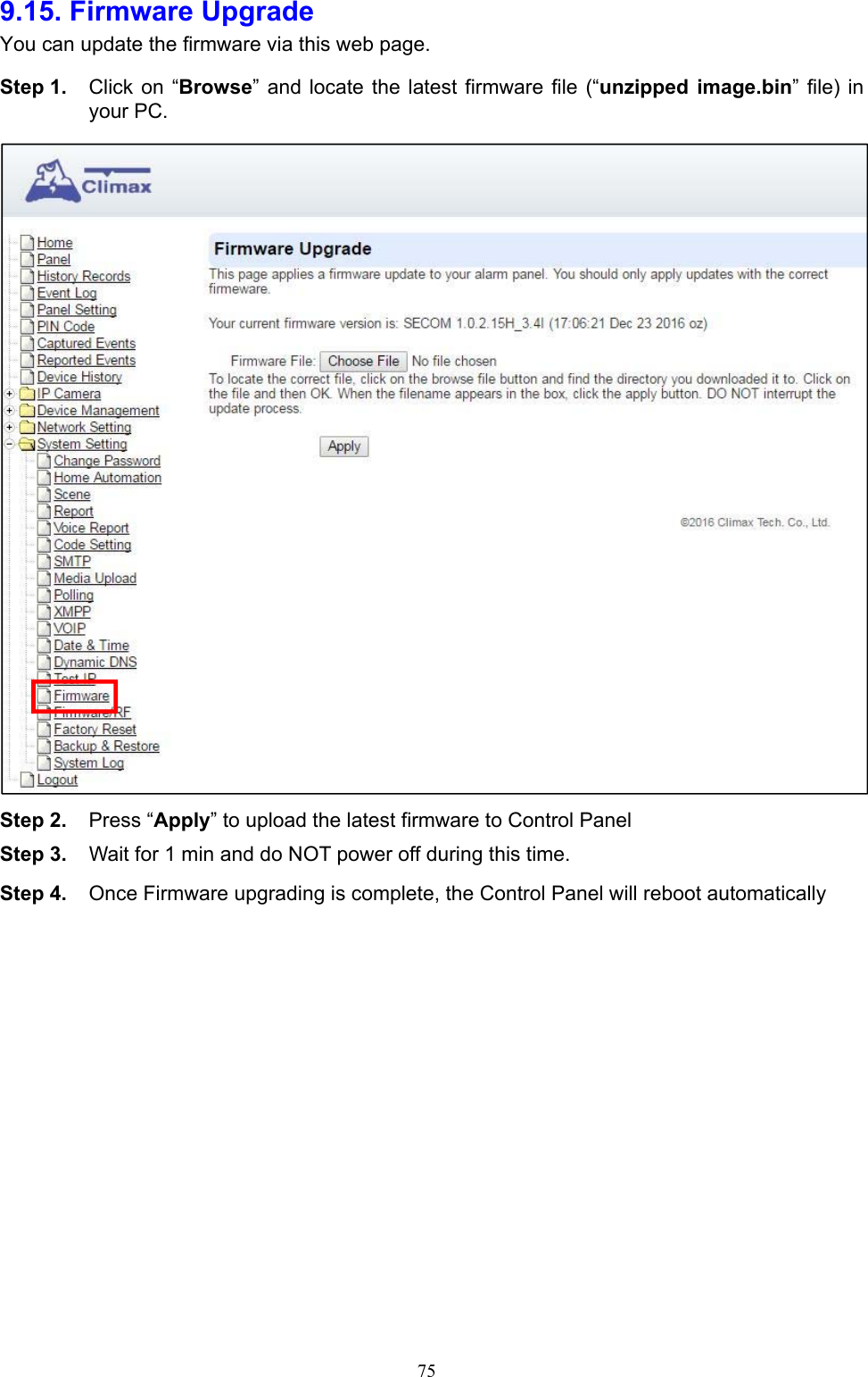
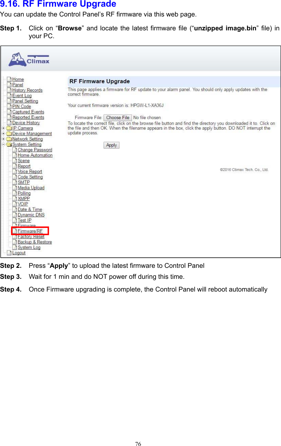
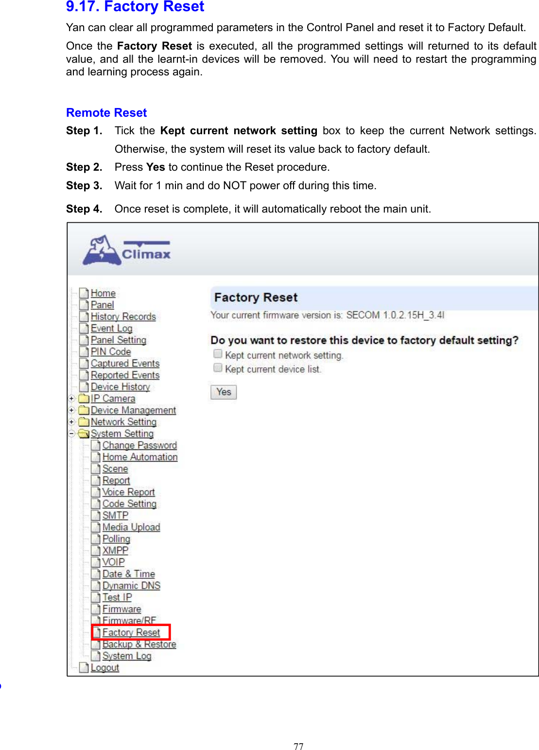
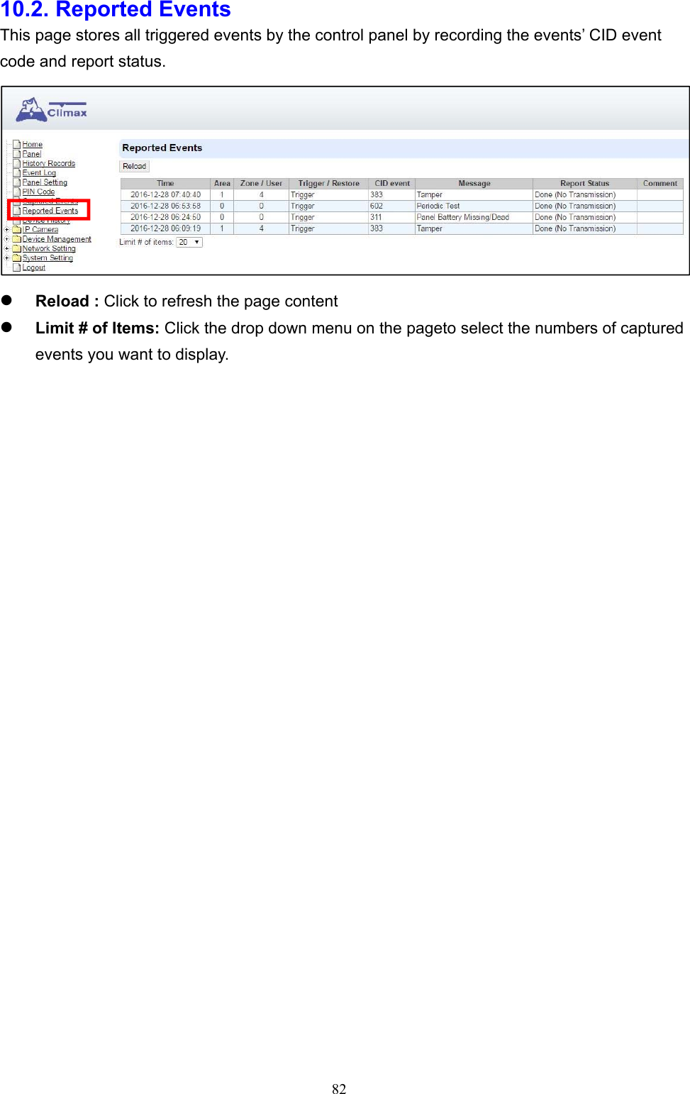
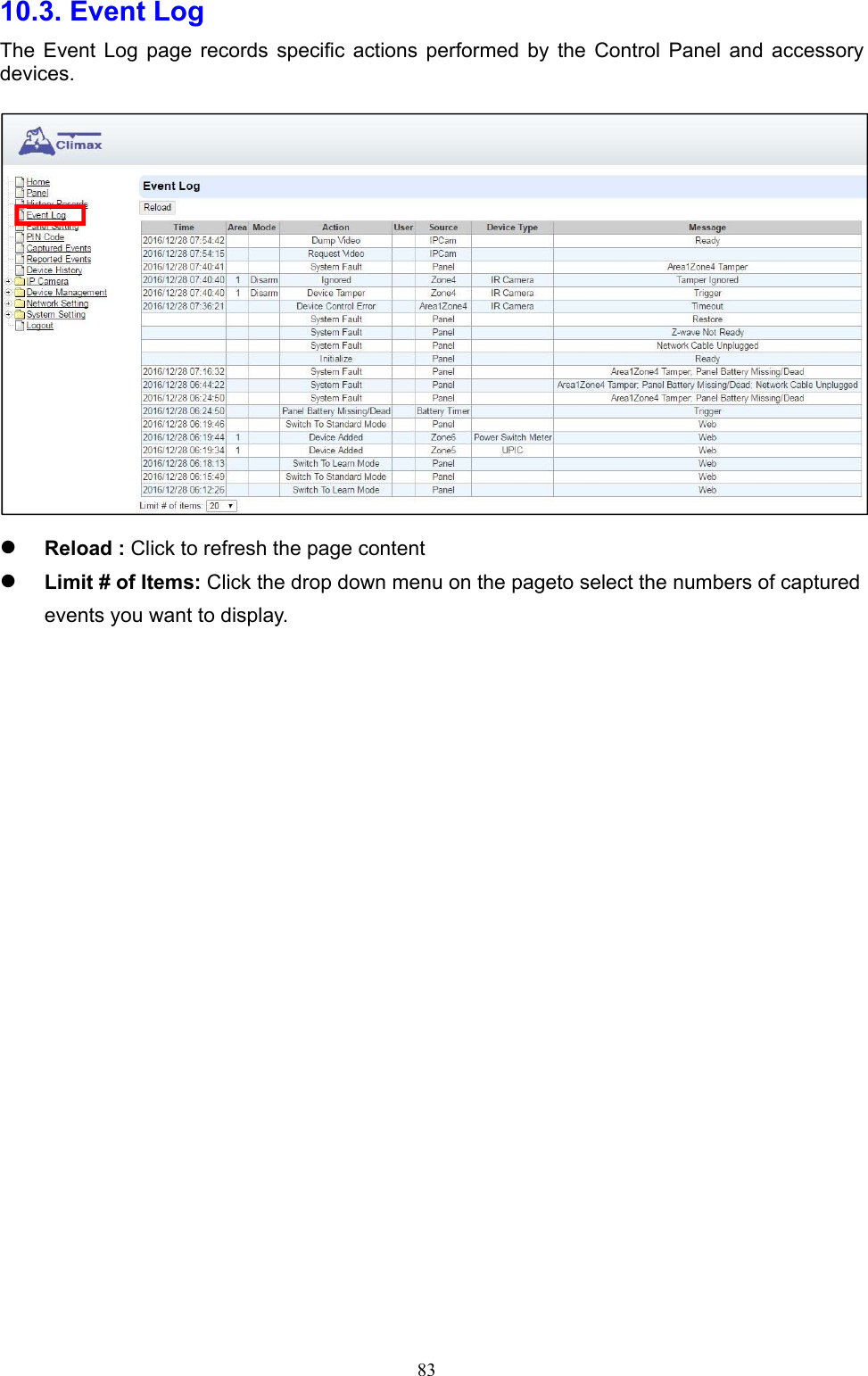
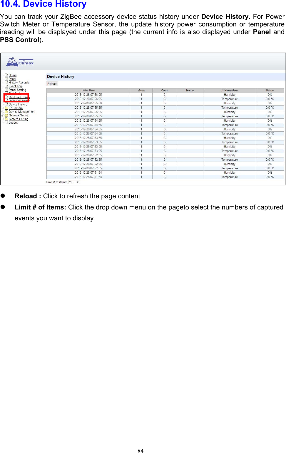
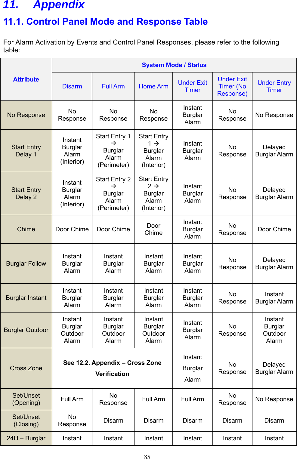
User Manual
Discussion / Help
Navigation