Clou IOT Technologies CLOUIOTCL7206B RFID Reader User Manual
Shenzhen Clou IOT Technologies Co.,Ltd. RFID Reader
User Manual
RFID reader
Model#: CL7206B
User Manual
CONTENTS
CHAPTER I, TECHNICAL SPECIFICATIONS .......................................................................................................................... 5
1.1, PRODUCT FEATURES ..................................................................................................................................................................... 5
1.2.MAIN FUNCTIONS & PERFORMANCE ........................................................................................................................................ 5
1.2.1 Main functions ................................................................................................................................................................... 5
1.2.2 performance parameters ............................................................................................................................................... 5
1.2.3.WORKING ENVIRONMENT ........................................................................................................................................................ 5
CHAPTER II, PHYSICAL STRUCTURE ..................................................................................................................................... 6
2.1 PHYSICAL STRUCTURE ................................................................................................................................................................... 6
2.2 WEIGHT ............................................................................................................................................................................................. 6
2.3 I/O interface & communication interface chart .......................................................................................................... 6
2.3.2 I/O aviation port chart ..................................................................................................................................................... 8
2.3.3 LED PANEL DESCRIPTION ....................................................................................................................................................... 9
2.4 EXTERNAL CABLE CONNECTION DESCRIPTION ................................................................................................................... 10
2.4.1 power supply & communication cable description ............................................................................................. 10
2.4.2 I/O control interface cable description .................................................................................................................... 11
2.4.3 External RF cable description ................................................................................................................................... 12
2.4.5 NETWORK CONNECTION CHART ............................................................................................................................................. 14
CHAPTER III, INSTALLATION ..................................................................................................................................................... 16
3.3 DEVICE CONNECTION ................................................................................................................................................................... 16
3.3.1 Connected to power adapter ..................................................................................................................................... 16
3.3.3 Connected with PC ........................................................................................................................................................ 17
3.4 HOW TO INSTALL THE READER .................................................................................................................................................... 17
3.5 INSTALLATION STEPS .................................................................................................................................................................... 17
3.5.1 Vertical pole installation ............................................................................................................................................... 17
3.5.2 Horizontal pole installation ............................................................................................................................................. 19
3.6 ACCEPTANCE ................................................................................................................................................................................. 20
3.6.1 checking physical installation ........................................................................................................................................ 20
3.6.2 checking reader performance ....................................................................................................................................... 20
CHAPTER IV, OPERATION GUIDE ........................................................................................................................................... 21
4.1 DEMO SOFTWARE FUNCTIONS ................................................................................................................................................... 21
4.2 SOFTWARE ENVIRONMENT .......................................................................................................................................................... 21
4.3 DEMO SOFTWARE VERSION NUMBER. ...................................................................................................................................... 21
4.4 TEST DEMO OPERATIONS ............................................................................................................................................................ 21
4.4.1 How to connect the reader .................................................................................................................................................... 21
4.4.2 Data display ......................................................................................................................................................................... 24
4.4.3 Write data .......................................................................................................................................................................... 28
4.4.4 TCP server /client mode ................................................................................................................................................. 30
4.4.5 Clock setting ........................................................................................................................................................................ 31
4.4.6 Hopping frequency management ................................................................................................................................ 32
4.4.7 tag filtering ........................................................................................................................................................................ 33
4.4.8 Automatic idle configuration .......................................................................................................................................... 34
In main UI, click “configuration”Æ”RFID configuration”Æ automatic idleÆ, dialog box pop up as per picture
4-18.................................................................................................................................................................................................... 34
4.4.9 GPI/O configuration .......................................................................................................................................................... 35
4.4.10 Tool ....................................................................................................................................................................................... 36
V, COMMON FAILURE PHENOMENON .................................................................................................................................. 39
5.1 DAILY MAINTENANCE .................................................................................................................................................................... 39
5.2 COMMON FAILURE ANALYSIS & RESOLUTIONS ........................................................................................................................ 39
5.3.MAINTENANCE WHEN NOT USED FOR LONG TIME. .............................................................................................................. 40
CHAPTER VI, PACKAGING, ACCESSORIES, TRANSPORTATION & STORAGE. ................................................. 41
6.1 PACKAGING: ................................................................................................................................................................................... 41
6.2 ACCESSORIES ............................................................................................................................................................................. 41
6.3 TRANSPORT REQUIREMENT. ....................................................................................................................................................... 41
6.4 STORAGE REQUIREMENTS .......................................................................................................................................................... 41

Chapter I, Technical Specifications
1.1, product features
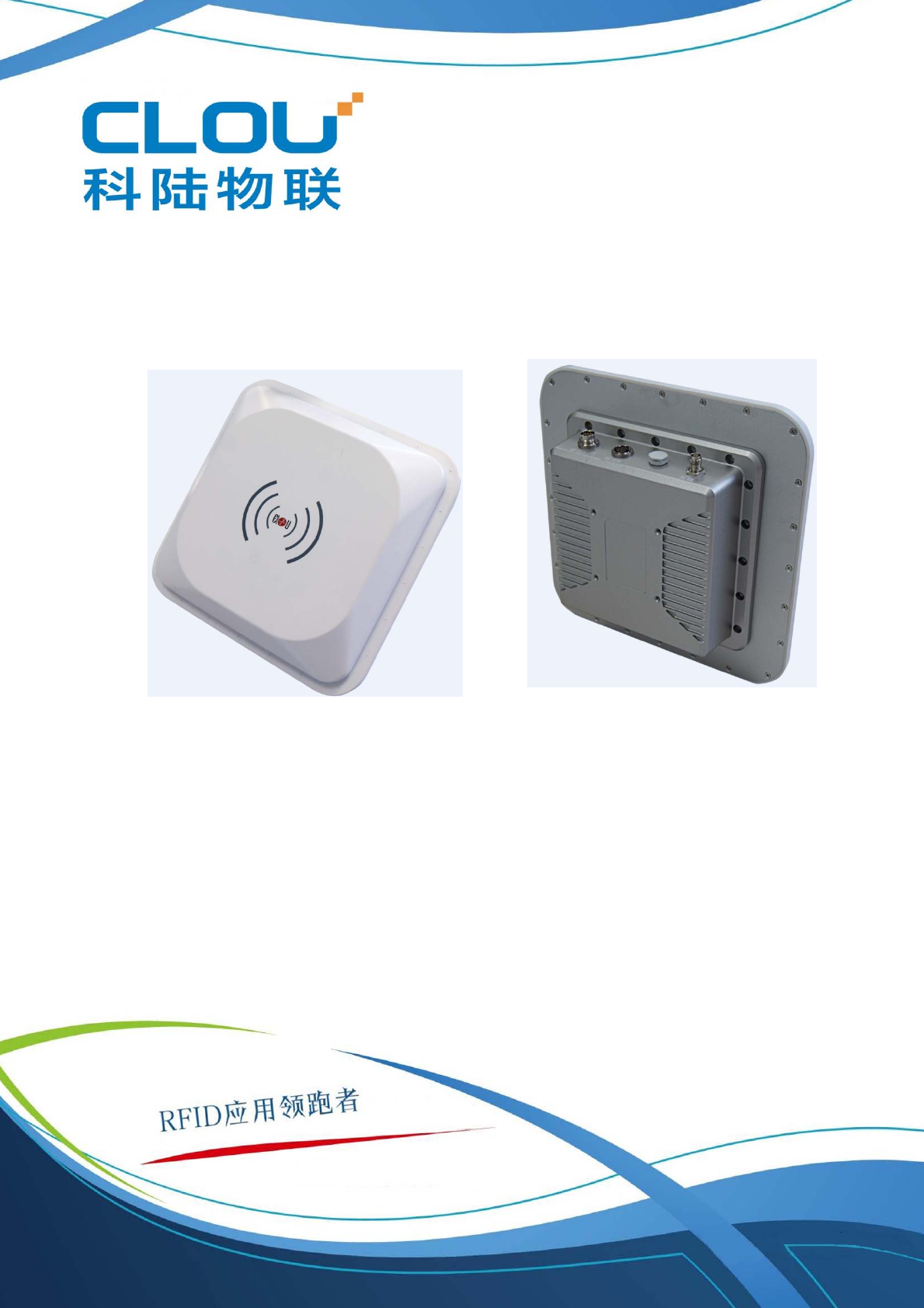
CL7206B2 is a high performance RFID reader which ingrates reader module & antenna. It complies with
ISO18000-6C/6B protocols, working frequency support international main frequency bands: 902MHz ~928MHz,
860MHz ~865MHz,Export power adjustable. This device is featured by long range, high-speed reading, & high
accuracy, high sensitivity, strong anti-interference etc.
1.2.Main functions & performance
1.2.1 Main functions
EPC protocol:support ISO18000-6C\6B & EPC C1G2 V1.1 mandatory commands.
Built-in LINUX operation system.
Rich communication interface(Ethernet, RS232, RS485)
Built-in circular antenna, support one external antenna.
Support tag data filtering.
Support RSSI: can sense signal strength
Support RF output power adjusting.
working mode: FH/HH optional.
support antenna inspection function.
Support online & remote upgrade.
IO interface: 2 relay input & 2 relay output, wiegand output.
1.2.2 performance parameters
Working frequency: 902MHz ~928MHz, 860MHz~865MHz etc.
RF output power(port):33dBm±1dB(MAX)
Output power adjusting: 1 dB step
Reading tag range 0~10meters( related with tag, antenna & using environment).
Channel bandwidth:<200KHz
Integrated circular antenna VSWR:≤1.4:1
Integrated circular antenna gain:≥8dBi
RS232 communication rate: 115200bps(default), 19200 bps,9600bps
RS485 communication rate: 115200bps(default), 19200 bps,9600bps
Wiegand output support wiegand 66, 34 & 26 types.
Power supply(power adapter): AC input 100-240V,50-60Hz
DC output 24V±1.5V/2.5A
1.2.3.working environment
Working temperature scope: -20℃~+30℃
Working humidity: 5%~90%RH(+25℃)
Chapter II, Physical structure
2.1 physical structure
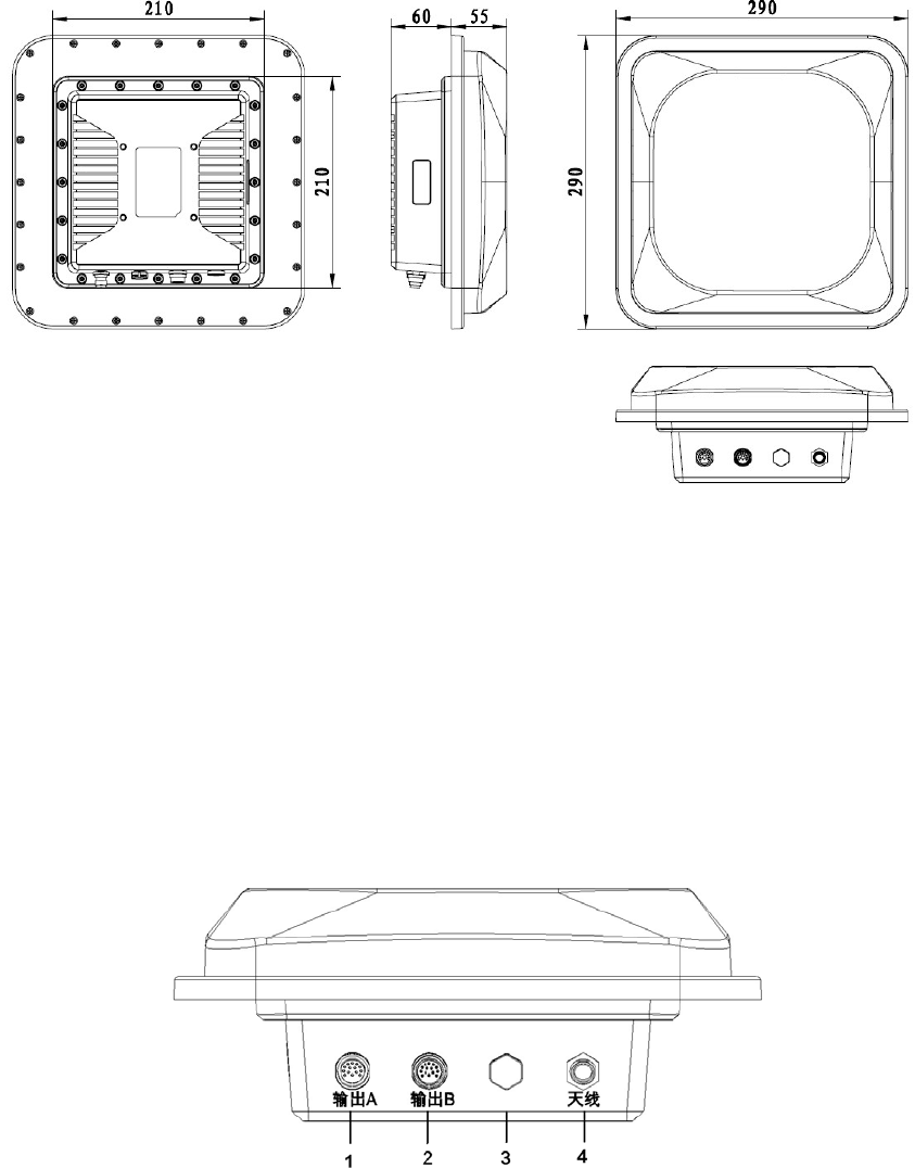
Picture 2-1 CL7206B structure chart
Physical size: 290mm×290mm×115mm(accessories not included)
2.2 Weight
2.5kg(accessories not included)
2.3 I/O interface & communication interface chart
Picture 2-2 I/O & communication interface
1 — power & communication port
2 — I/O control interface
3 — Ventilation valve
4 — antenna port
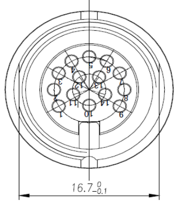
2.3.1 Power supply & communication interface description
Picture 2-3 power supply & communication port aviation port number chart
Aviation plug signal definitions
Chart 2-1 Power & communication interface signal definition
PIN Description PIN definition
1 Power supply GND PGND
2 Power supply GND PGND
3 24V power positive +24V
4 24V power negative +24V
5 NC NC
6 NC NC
7 NC NC
8 Ethernet port TD-
9 Ethernet port TD+
10 RS232 receiving RXD RX
11 S PGND
12 Ethernet port RD-
13 Ethernet port RD+
14 RS232 receiving RXD TX
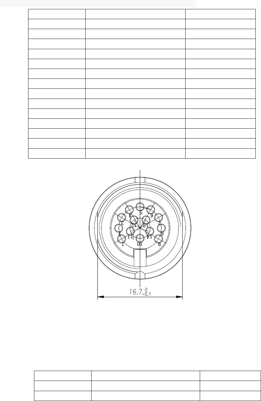
2.3.2 I/O aviation port chart
Picture2-4 I/O interface aviation port number chart
I/O aviation port definition as per in chart 2-2:
Chart 2-2 I/O port signal function definition
PIN No. Description PIN definition
1 Relay 1 output port R1
2 Relay 1 output port L1
3 Relay 2 output port R2
4 Relay 2 output port L2
5 Optocoupler 1 external signal input
anode IN1
6 Optocoupler 2 external signal input
anode IN2
7 Optocoupler external signal input
cathode IGND
8 Wiegand output 0 WG0
9 Wiegand output 1 WG1
10 地 AGND
11 地 AGND
12 RS485 signal 485+
13 RS485 signal 485-
14 地 AGND
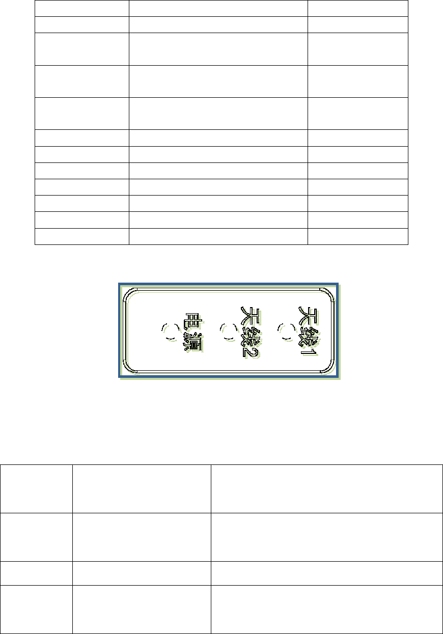
2.3.3 LED panel description
Picture 2-5 LED panel chart
LED panel description as per in chart 2-3:
Chart 2-3 LED definition description
LED Mark
No. Description Status description
ANT1 Antenna 1 LED
Means external antenna port successfully
selected
ANT2 Antenna 2 LED Means built-in antenna successfully selected
PWR Read/write card status
Flickering means entering normal card reading
status.
2.4 External cable connection description
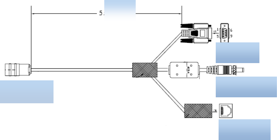
2.4.1 power supply & communication cable description
Cable Specifications: Black insulated skin with metal screening net, 14 shares inner core, outer
diameter 7.8mm, main cable length is 4m, branch cables length are 1m. As shown in below picture, the
aviation plug connected with the reader "Power and communication interface," while 14 core lines are for
the three different signal path, i.e. "serial cable, DC power cord and network interface cable ", mainly used
for power supply and data transmission.
Picture2-6 电源及通信接口线材分解示意
Aviation plug
RS232 port
Power supply port
Ethernet port
meter
Picture2-7 Power supply & communication aviation plug chart
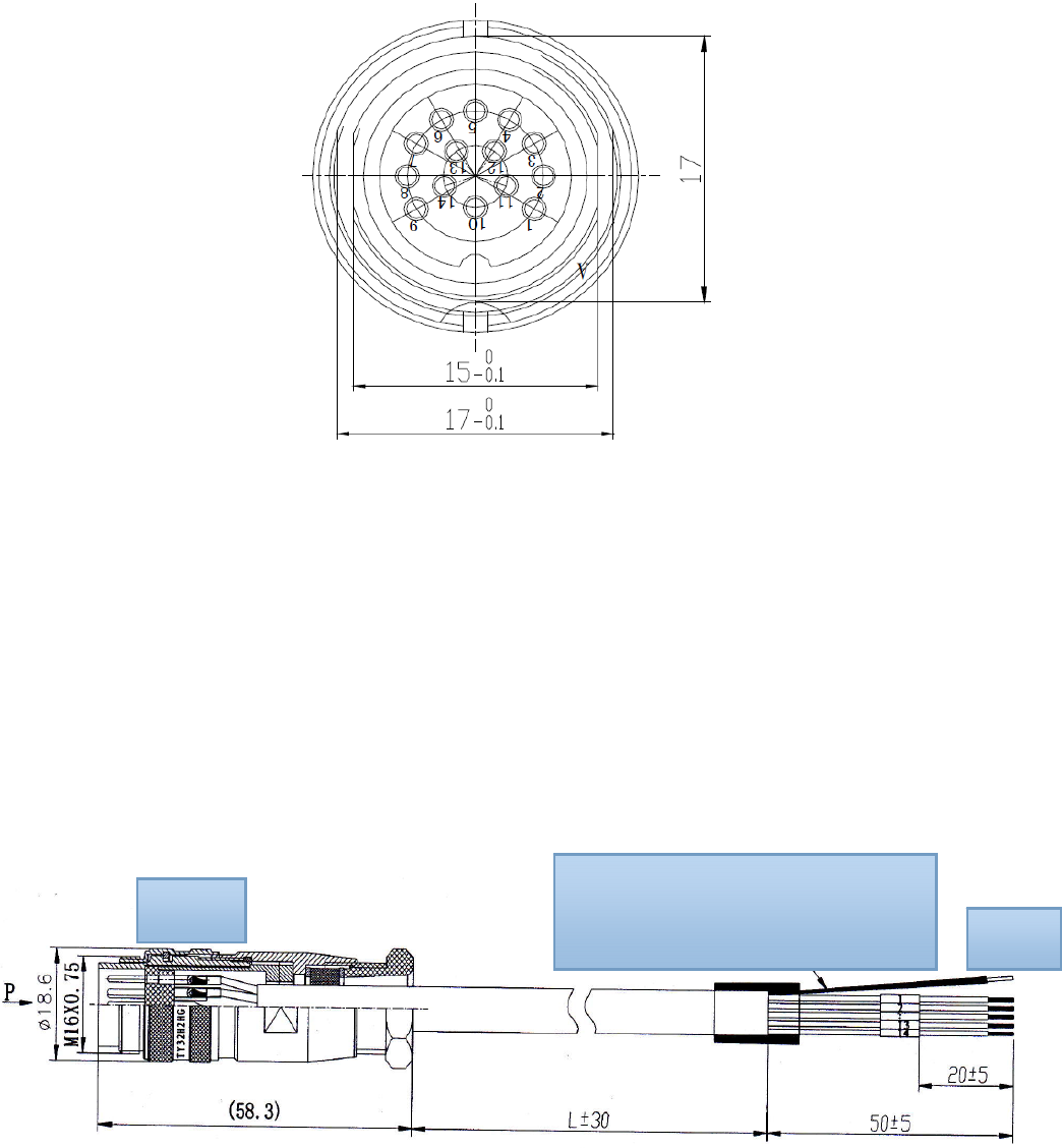
2.4.2 I/O control interface cable description
Cable Specifications: Black insulating skin with metal screening net, 14 shares inner core, outer diameter
7.8mm, the main cable length is 2.5m, "aviation plug “ is connected with reader "I / O control interface", 14
core lines mainly provides two-way optical coupling input port, two-way relay control ports, two Wiegand output,
two-way communication port 485. Mainly used for input trigger reading, peripherals switch control, upload
card data, and communication functions, see Table 2-4 I / O control aviation seat definition table.
Chart 2-8 I / O control interface cable chart
Shielded wire are twisted into one and
covered b
y
heat shrink tubin
g
.
Port A
Port B
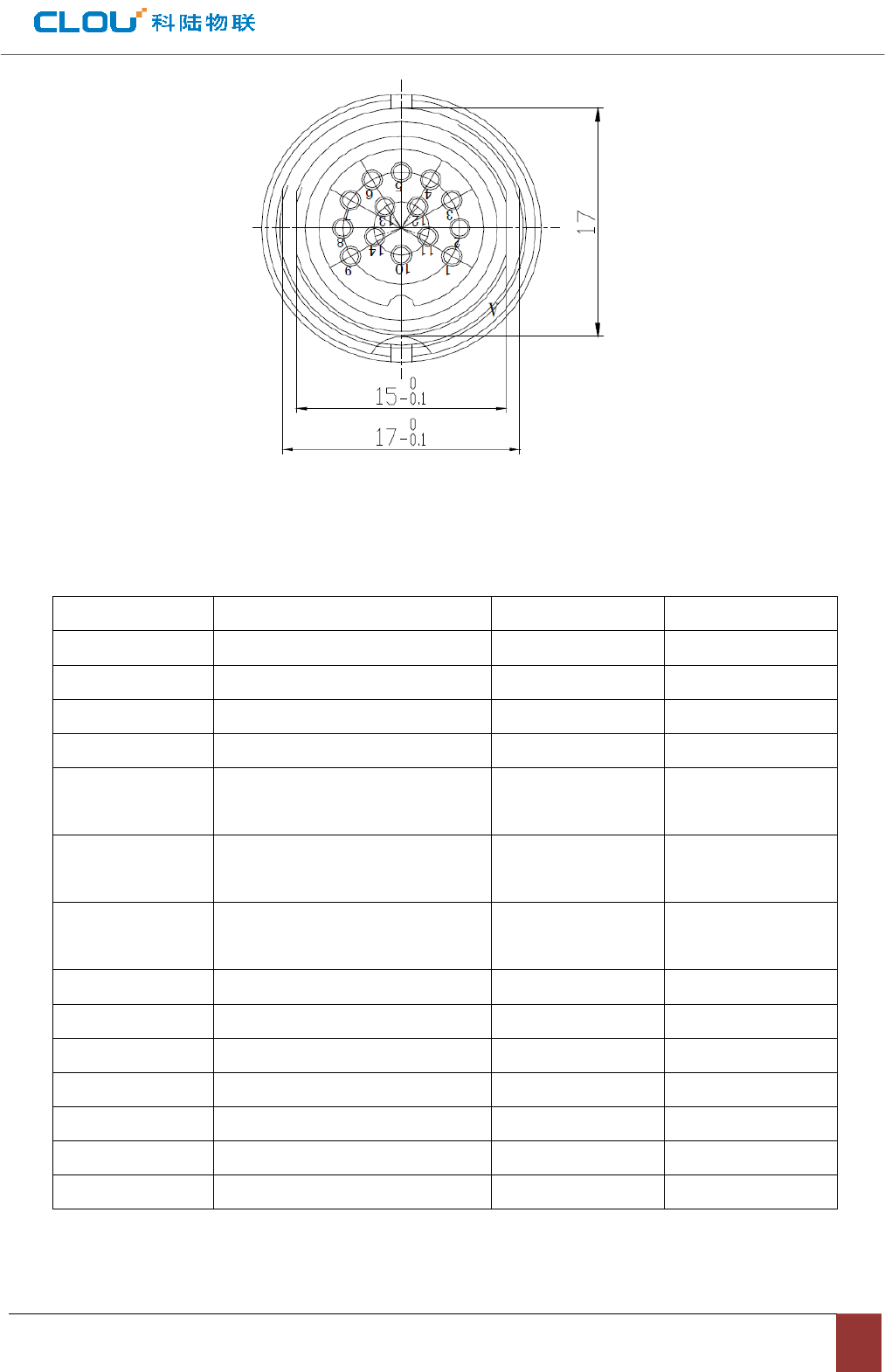
Chart 2-9 I/O control aviation seat illustration
The other end of the cable is bare and tin thread, can distinguish the functions defined by the color of the cable.
Chart 2-4 I/O control avaiation seat definition table
No. PIN description PIN Color Marking number
1 Relay 1 output port White 6
2 Relay 1 output port Blue 8
3 Relay 2 output port White/black 7
4 Relay 2 output port Blue/black 9
5 Optocoupler 1 external signal
input anode
Grey/black
5
6 Optocoupler 2 external signal
input anode
Grey
4
7 Optocoupler external signal input
cathode
purple/black
3
8 Wiegand output 0 purple 2
9 Wiegand output 1 Green/black 1
10 Ground Green 10
11 Ground Yellow/black 14
12 RS485 signal Yellow 13
13 RS485 signal Red/black 12
14 Ground Red 11
2.4.3 External RF cable description
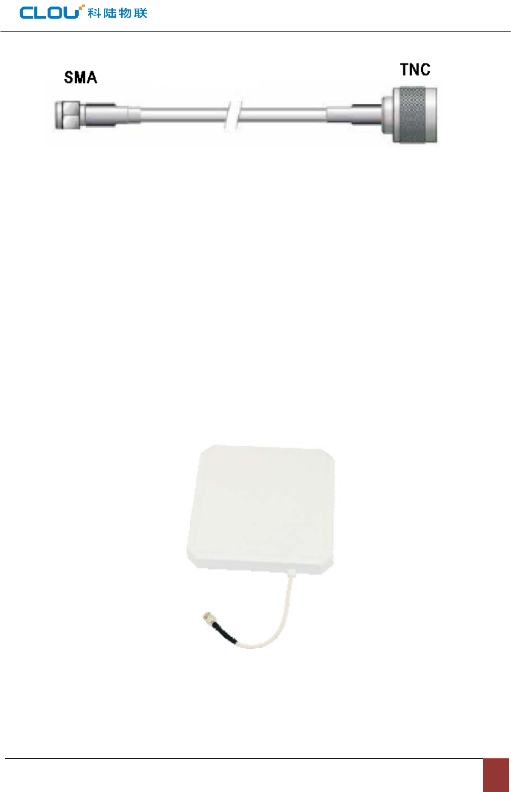
Picture 2-10 RF cable schematic chart
The connector between RF cable & reader is TNC male, the connector between RF cable & antenna
is SMA male connector (depending on antenna connector as well). Try to keep the cable length within
5meters, impedance 50Ω, the insertion loss less than 2dB. Of course, you can choose a
high-performance cable, appropriately increase the length, but keep the insertion loss less than 2dB.
Note: Too long RF cable or cable poor connection will cause high signal attenuation & poor reader
performance.
2.4.4 External antenna description (optional)
This reader has a integrated circular antenna. User can also connect one more external antenna. It is
recommended to use the external antenna provided by our company.
Picture 2-11 Circular antenna

Antenna performance parameters:
Work frequency: 902~928 or 860~865 MHz
Gain: 8 dBic
Maximum VSWR: 1.3:1
Polarization: L Circular Right or left
Input impedence: 50 Ohms
Weight: 2.3lbs
Mechanical size: 10.2” x 10.2” x 1.32”
Antenna Connection: coax pigtail, Rev INC Males
Working temperature: -20℃~30℃
Lightning protection: DC grounded
Environmental rating: IP54
2.4.5 Network connection chart
Ethernet connection is used for long range high speed connection (within 80meters). Can connect
through router or exchanger or PC Ethernet port. Refer to below picture.
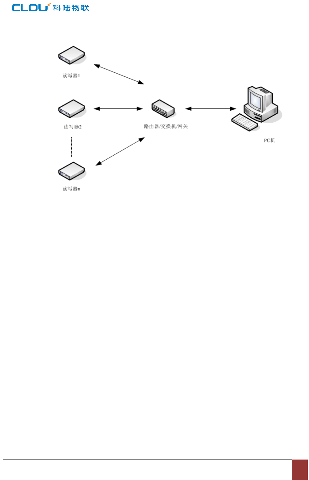
Picture 2-12 Ethernet connection chart

Chapter III, Installation
3.1. Precautions
In order to ensure normal and stable operation of the equipment and your personal and property safety, before
installing CL7206B reader device, please carefully read the following notes.
1. First check whether the outlet is connected to earth ground, and check if the local power supply voltage meet
reader voltage requirements.
2. Check if the device is connected tightly and the metal house of the device is connected with ground.
3. pay attention to the network cable and serial cable type selection and length restrictions;
4. When installing multiple readers, pay attention to reader antenna display way & the minimum distance
between the antennas , avoid the situation that interference may affect the reader's performance;
5, please test & ensure the reader can work normally before using it.
3.2 Installation conditions
Before installing the reader, please check carefully whether the product is intact, the accessories are complete.
3.3 Device connection
3.3.1 Connected to power adapter
☆ Connect power adapter to AC power socket, and the other end to reader power support interface.
☆ After the circuit is connected, wait for about 20seconds, reader makes two alarming sound and
enter into initialization state, after initialization is finished, reader enter into standby mode.

3.3.2 Connect an external antenna and RF cable
☆ The reader housing has a TNC-type coaxial connector for connecting an external antenna. Please use
low-loss RF cable. The connection between the joints should be tightened (for outdoor installation joints please
pay attention to water).
☆ reader external antenna is usually placed at outdoor. Its beam coverage is the effective reading range (try to
avoid other objects occlusion).
☆ according to onsite situation, the reader antenna angle should be adjusted to the best condition till when the
reading performance reaches its best after testing.
3.3.3 Connected with PC
☆ RS-232 interface is used for short-range communication (less than 10m), can be connected to a PC via the
serial port connector for communication.
☆ RJ45 Ethernet port is used for longer range communications (less than 80m), can use extended network
cable to connect the PC and RJ45 interface.
3.4 How to install the reader
According to field situation, preliminarily confirm the reading range. According to field read/write testing result,
adjust antenna (rotation) angle, to make the reading performance reaches its best. Finally, Fixed the device
and the tilt (rotation) angle.
3.5 Installation steps
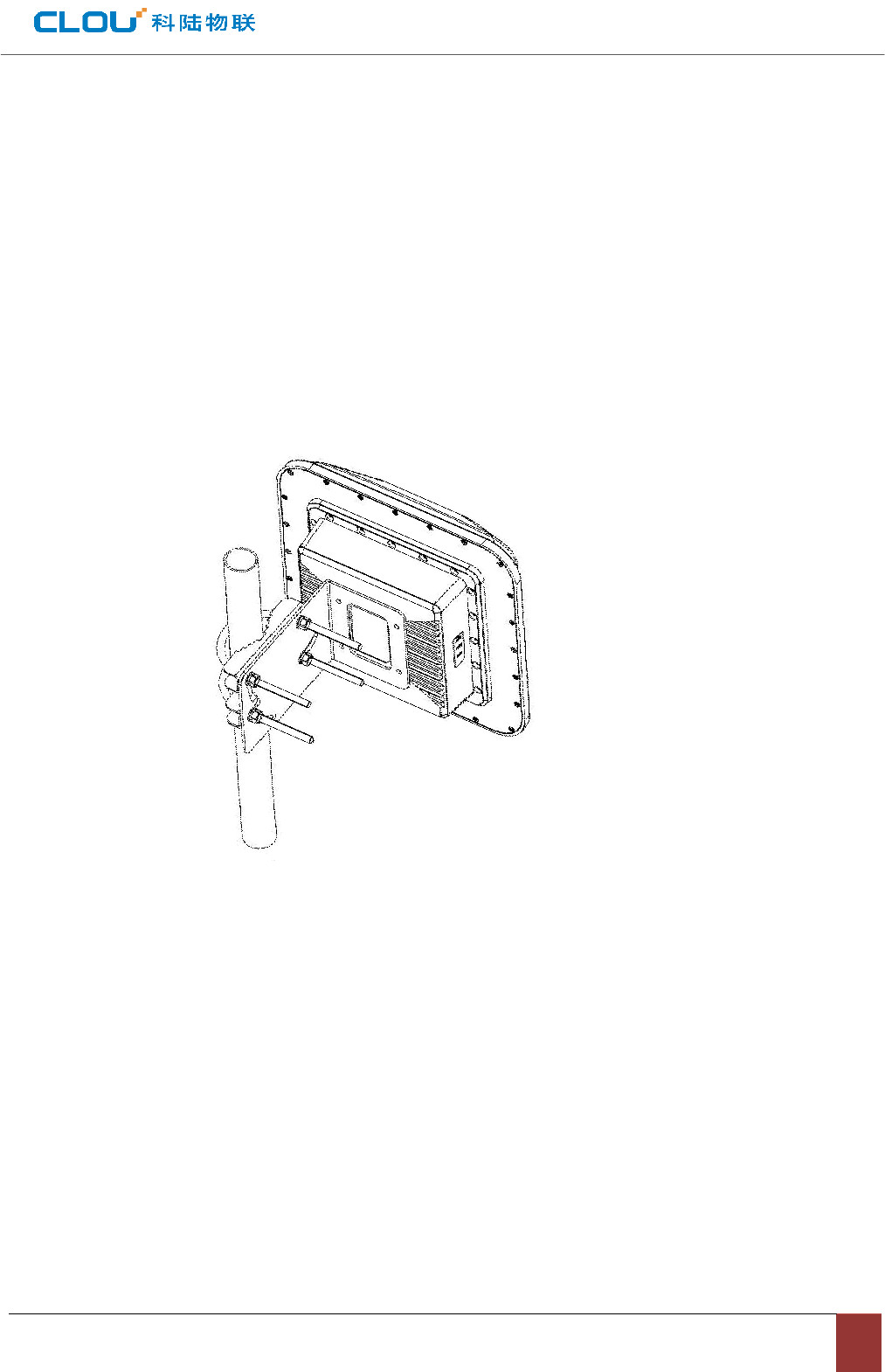
3.5.1 Vertical pole installation
(1)Align the L-shaped mounting bracket against the holes on bottom of reader housing, use four hexagon
socket head cap screws GB70-85 M5 * 12 for tightening. . Shown in picture 5-1:
Picture 0-1 wall installation
(2) Using two U-bolts and two toothed installation bracket to fix the reader on vertical rod through the L-bracket.
As per illustrated in picture 5-2.
Note: This installation method is suitable for 50mm ~ 100mm diameter vertical pole.
Picture 0-2 Vertical pole installation
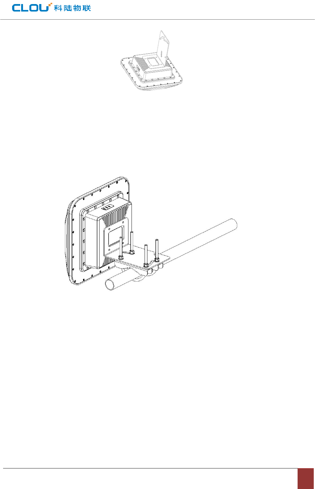
3.5.2 Horizontal pole installation
(1)Align the Align L-shaped mounting bracket against the holes on bottom of reader housing, use four
hexagon socket head cap screws GB70-85 M5 * 12 for tightening. Refer to picture in 5-3:
(2) Using two U-bolts and two toothed installation bracket to fix the reader on vertical rod through the
L-bracket. As per illustrated in picture 5-3.
Note: This installation method is suitable for 50mm ~ 100mm diameter horizontal pole.
Picture 0-3 Horizontal pole installation

3.6 Acceptance
3.6.1 checking physical installation
Check & ensure the reader is fixed safely;
Check & ensure cables are connected securely.
Check & ensure screws are screwed firmly.
3.6.2 checking reader performance
☆ check & confirm the reader is working normally;
☆ check & confirm the reading range is set properly.

Chapter IV, Operation Guide
4.1 Demo software functions
The demo software is for system control, communication mode selection, parameters setting, tag
reading/writing & data display etc.
4.2 Software environment
Windows 2000 Service Pack 3, Windows Server 2003, Windows XP Service Pack 2, Windows 7.
Hardware environment
P4/1.7GHzor above,512M memory or above、40G hardware disk.
4.3 Demo software version number.
Demo V1.0.0
4.4 Test demo operations
4.4.1 How to connect the reader
4.4.1.1 RS232 connection
After the reader power supply cable & PC communication cable are connected well, open Demo software,
the icons on main UI are all in grey color, means reader is not connected. Select communication/connect mode
as“RS232 connect”, & parameter as “COM?”(“?” means COM No.),communication port as “115200”(default
value),click“confirm”button, as in picture 4-1.
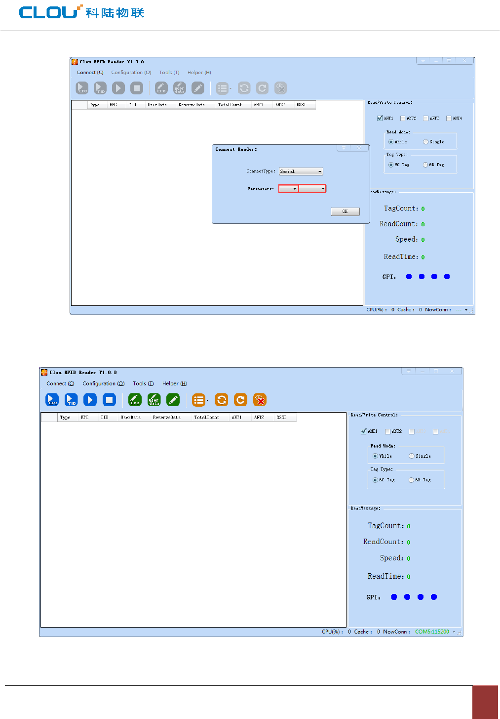
Picture 4-1 RS232 connection
When successfully connected, all icons are light, as per in picture 4-2, means RS232 connection success.
Picture 4-2 RS232 connection successful
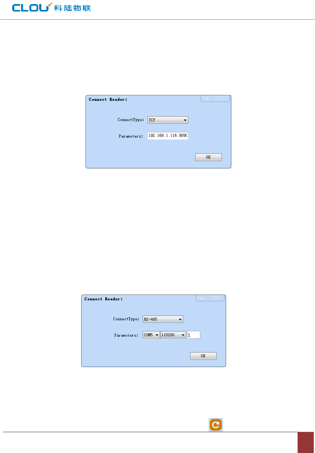
4.4.1.2 Ethernet port communication connection
Ethernet is used for long range connection(within 80meters), can connect with exchanger, router or PC
Ethernet port directly. Choose communication/connect mode as “TCP connection”, input the reader IP (default
192.168.1.116), input communication port number (default 9090), click “confirm” button. As per in picture 4-3.
Picture4-3 Ethernet communication port
The reader default IP address is write as “192.168.1.116” before ex-factory. If you want to modify that, you
can use RS232 connection to set up connection, then check the current IP address. Choose “Configurations”Î
“Senior” ΔReader configuration”, set IP address in the promp-out box “reader setting” under network port.
4.4.1.3 RS485 connection
Choose “485 connection (COM)” in the draw-down list of connection way, choose “COM?” (“?” stands for
COM No.”), choose communicate rate as “115200”, input RS485 address and then click “confirm” button. As
per in picture 4-5.
Picture4-5 485 communication connection
RS485 address default is 1.
RS485 address range is 1~255.
Remarks: after the configuration is changed, please click the button .
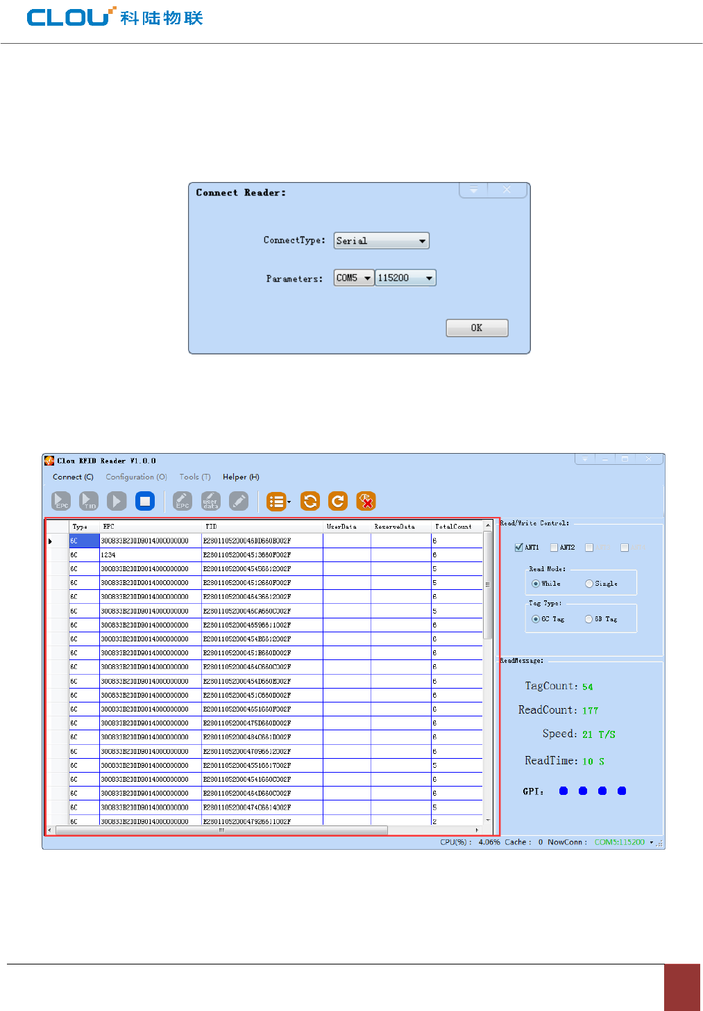
4.4.1.4 USB connection
In the pull-down menu of reader connection, choose “serial port connection” as communication way,
choose “ COM?” (“?” stands for USB serial port number detected by PC), choose “115200” (default) as
communication rate, click “confirm”, as per in picture 4-6.
Picture4-6 USB connection
4.4.2 Data display
Picture 4-7 data display area parameters definition
Type:Tag type 6C、6B
EPC: Tag’s EPC data, can write /read.

TID: Tag’s TID data, unique number, read only.
UserData:user data area, read/write.
ReserveData:reserved data area, to store tag password etc.
TotalCount:Total tag reading cycles.
ANT1: No. 1 antenna reading cycles
ANT2: No. 2 antenna reading cycles
RSSI:signal strength

4.4.2.1 Read EPC
Click button, data display area will show read EPC data.
EPC display as hexadecimal string, length unit is word (1 word =2 bytes = 4 hexadecimal characters). If
you want to read user-defined length EPC data, please refer to 4.4.2.3 user-defined read.
4.4.2.2 Read TID
Click button, data display area will show the existing EPC data and TID data.
TID displays as hexadecimal string, length unit is word (1 word =2 bytes = 4 hexadecimal characters). TID
default length is 6 words.
If you want to read user-defined length TID data, please refer to 4.4.2.3 user-defined read.
4.4.2.3 User-defined read
Click button, prompt box as in picture 4-8.
Choose “6C tag configuration” for matching reading, you can read matching tags through existing EPC or
TID data.
Read TID: choose tag TID data, read mode default as “self-adaptive”, reading length unit is word.
Read user area: choose tag user area data, the start address & reading length takes “word” as unit.
Read reserved area: choose tag reserved area data, the start address & reading length takes “word” as
unit.
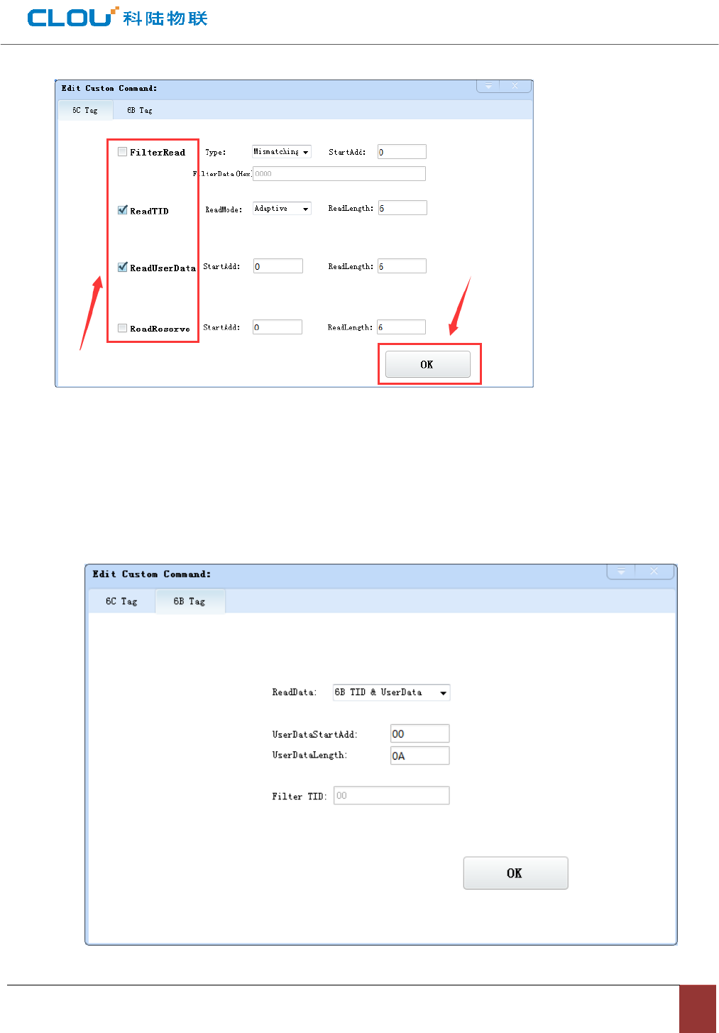
Picture 4-8 6C tag user-defined configuration
Choose “6B tag configuration”, prompt box as in picture 4-9.
Can choose TID data or user data for reading.
Can operate TID match reading.
Indications: you can ignore this function when you are not familiar with the tag protocol.
Picture 4-9 6B tag user-defined configuration
4.4.2.4 stop reading
Click button to stop all the read/write operations.
4.4.3 Write data
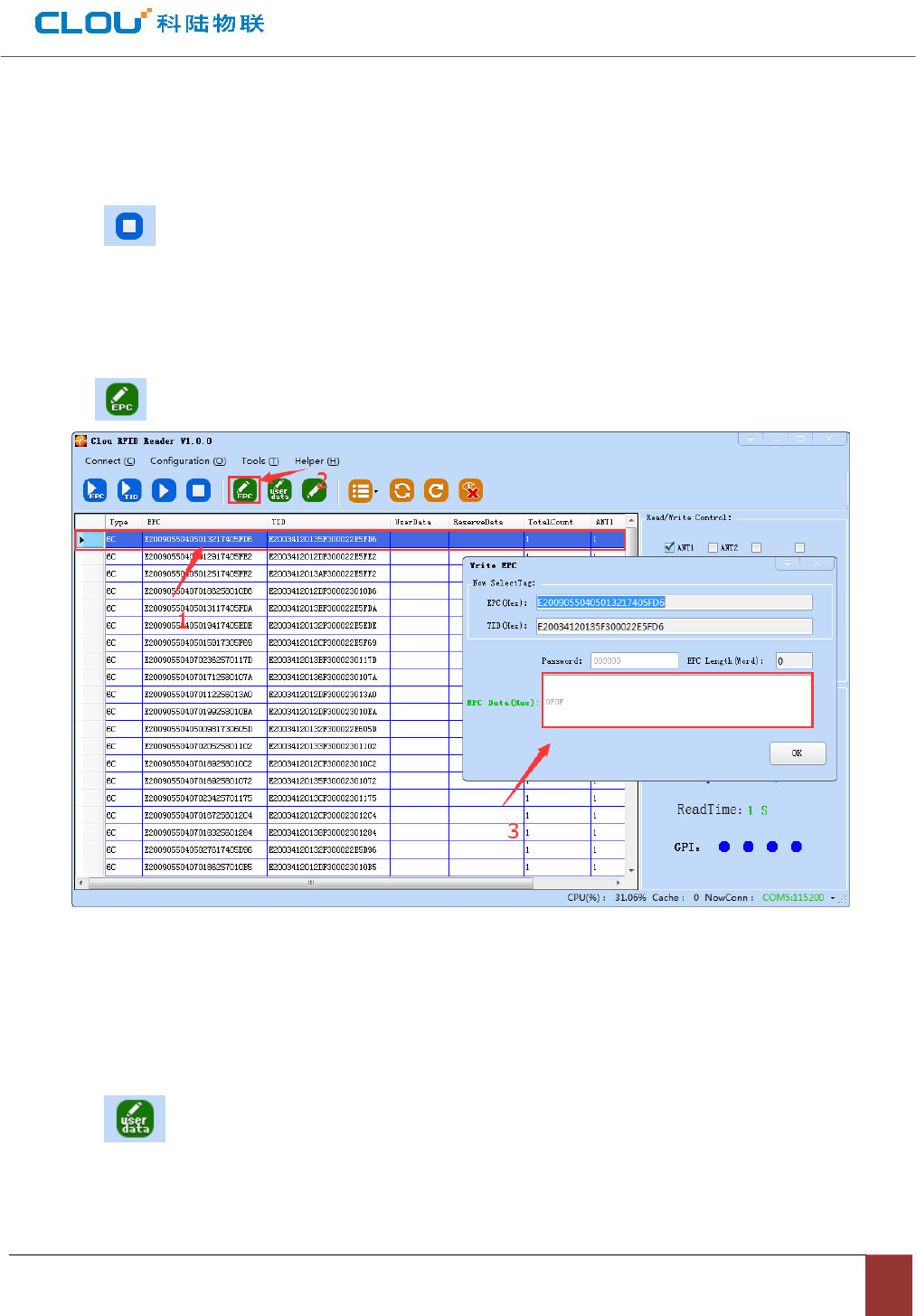
4.4.3.1 write EPC data
Click button, prompt box as in picture 4-10.
Picture 4-10 write EPC data
Choose one tag data (which includes TID information), input EPC data (Hexadecimal string), click
“confirm”.
4.4.3.2 write user data
Click button, pop up dialog box as in picture 4-11.
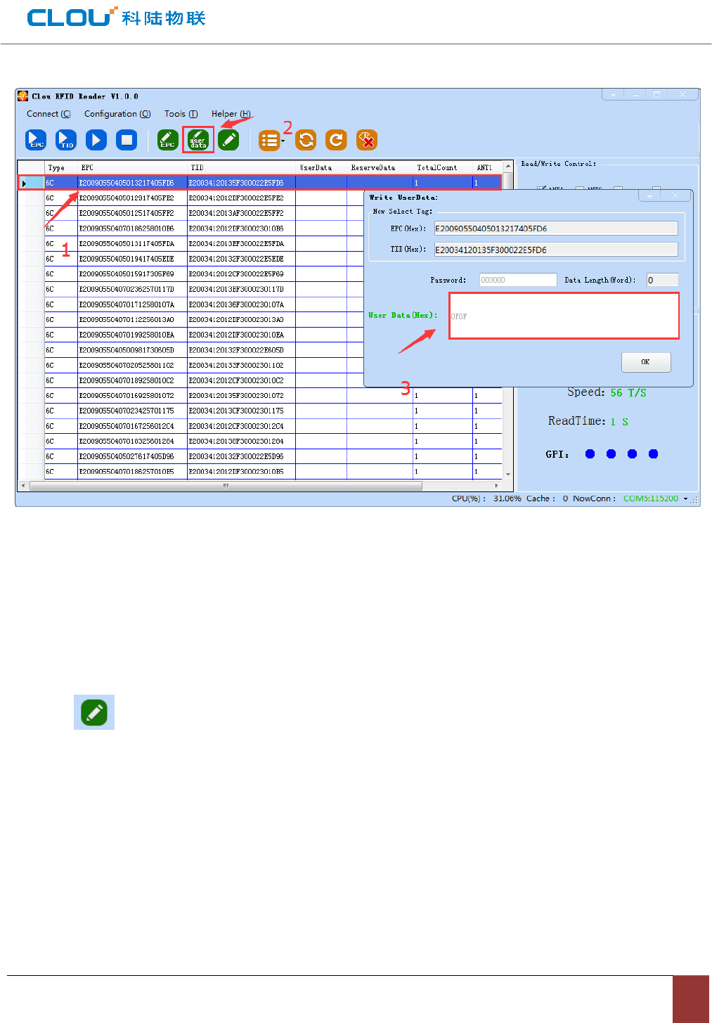
Picture 4-11 write user data
Choose one tag data (which includes TID information), input user data (Hexadecimal string), click
“confirm”.
4.4.3.3 user-defined definition tag operation
Click butto, pop up dialog box as per picture 4-12:
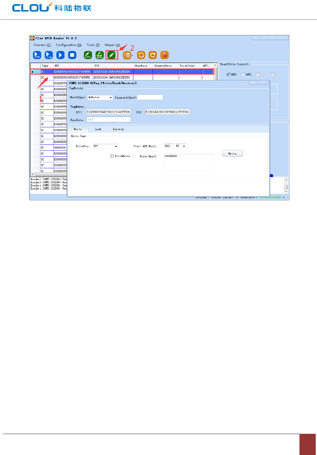
Picture 4-12 user-defined tag operation
1. choose one tag data;
2. click “user-defined” button;
3. Operate write/read/lock operations based on reader protocol.
4.4.4 TCP server /client mode
Open demo main UI, choose “configurations” Δreader configuration”Î TCP server, pop up dialog box
as per picture 4-13:
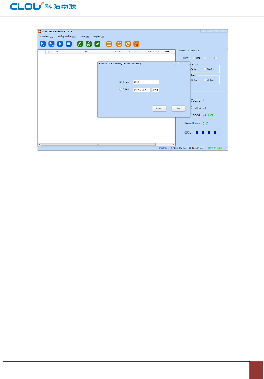
Picture 4-13 mode setting
When reader is configured as “server” mode, connection is launched by PC; when reader is configured as
“client” mode, reader will connect with PC automatically.
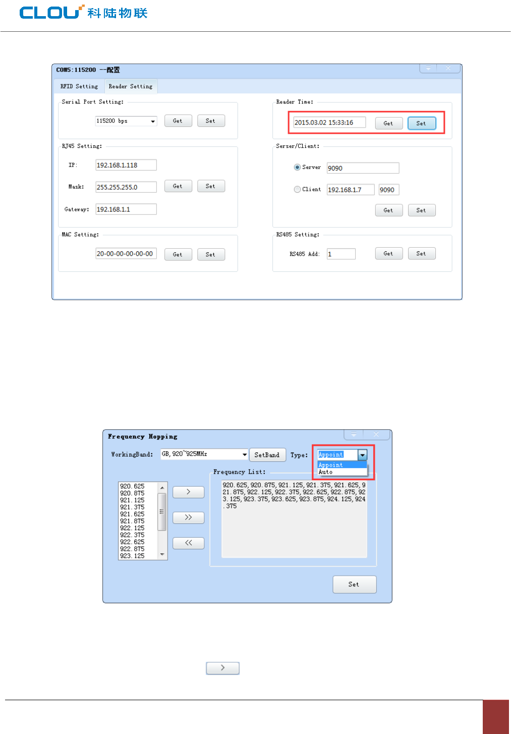
4.4.5 Clock setting
In Demo main UI, choose “ configuration”Æ “Senior”Æ”reader setting”, pop up dialog box as per picture
4-14. In “reader time” area you can check reader current time. If you want to modify reader time, you can make
modifications at first and then click “configure” for confirmation.
Picture4-14 clock display configuration
4.4.6 Hopping frequency management
At main UI, click “configuration”Î RFID configurationÆ Hopping frequency management, a dialog pop up
as per picture 4-15.
Picture 4-15 Hopping frequency management
In pull-down list of “working frequency”, choose “GB,920-925MHz”, click “setting frequency”, choose
frequency point (as per picture 4-15), click button to import into the box on the right, click “configure”
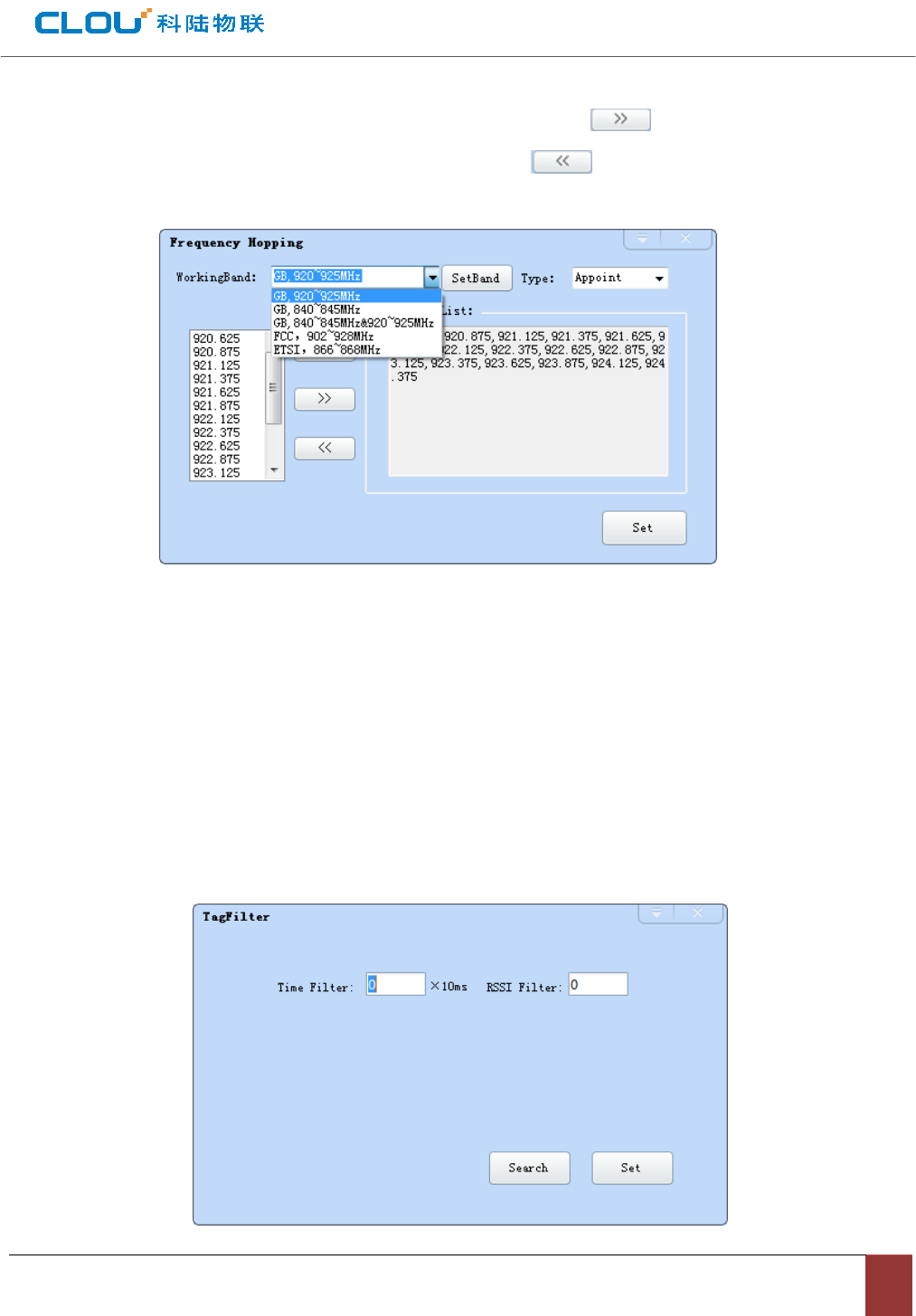
for confirmation; If you want to choose full frenqency hopping, just click . All the frequency points will be
displayed in the box, click “configure” for confirmation. If click , all frenqency point in the box will be
deleted.
Picture4-16 FH selection
Notice: In hopping frequency management, the option “automatic” is for avoiding external signal
interference, thus choosing high speed frequency hopping. Default setting is “automatic” as per indicated
in picture 4-15.
4.4.7 tag filtering
Open the demo, click “configuration”Æ “RFID configuration”Æ “tag filtering”, dialog box pop up as per in
picture 4-17.
Picture4-17 tag filtering
Filtering time: means in an operation period, in designated filtering time, same tag data will be uploaded
one time. 0~65535,time unit: 10ms.
RSSI threshold value: when tag RSSI lower than threshold value, tag data won’t be uploaded. Will be
abandoned.
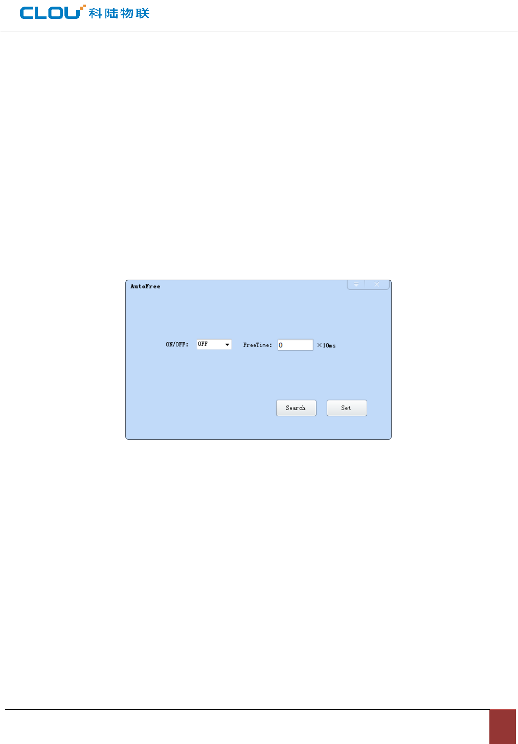
4.4.8 Automatic idle configuration
In main UI, click “configuration”Æ”RFID configuration”Æ automatic idleÆ, dialog box pop up as per
picture 4-18.
Picture 4-18 Automatic idle configuration
Automatic idle mode means during reading tags continuously, all antennas didn’t identify tags for three
polls, reader will enter idle mode for a time for saving power. After idle time is finished, reader enter card
reading status automatically.
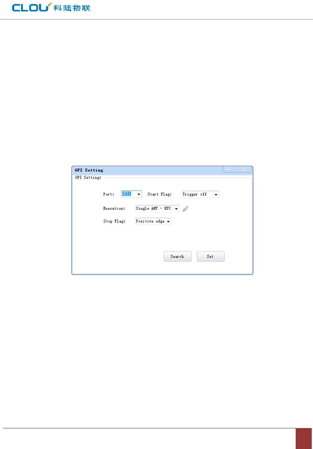
4.4.9 GPI/O configuration
GPI/O control provide enquiry and setting I/O port status, controlling I/O device functions.
GPI configuration
In Main UI, choose “configuration”ÎGPI/O configurationÆ GPI configuration”, pop up dialog box as per
picture 4-19. Choose triggering conditions and click “configuration” for confirmation.
Picture 4-19 GPI configuration
z Inquiry: inquiry each port triggering parameters.
z Configuration: choose the port to be set and then click “configuration” for confirmation.
z Triggering start condition: choose the mode from pull-down list.
z Triggering execution command: choose the mode from pull-down list.
z Triggering stop condition: choose the mode from pull-down list.
z Remarks: when triggering conditions are satisfied, reader will execute configured command.
GPO configuration
In main UI, choose “ configuration”Æ “GPI/O configuration”Æ “GPO configuration”, pop up dialog box as
per picture 4-20.
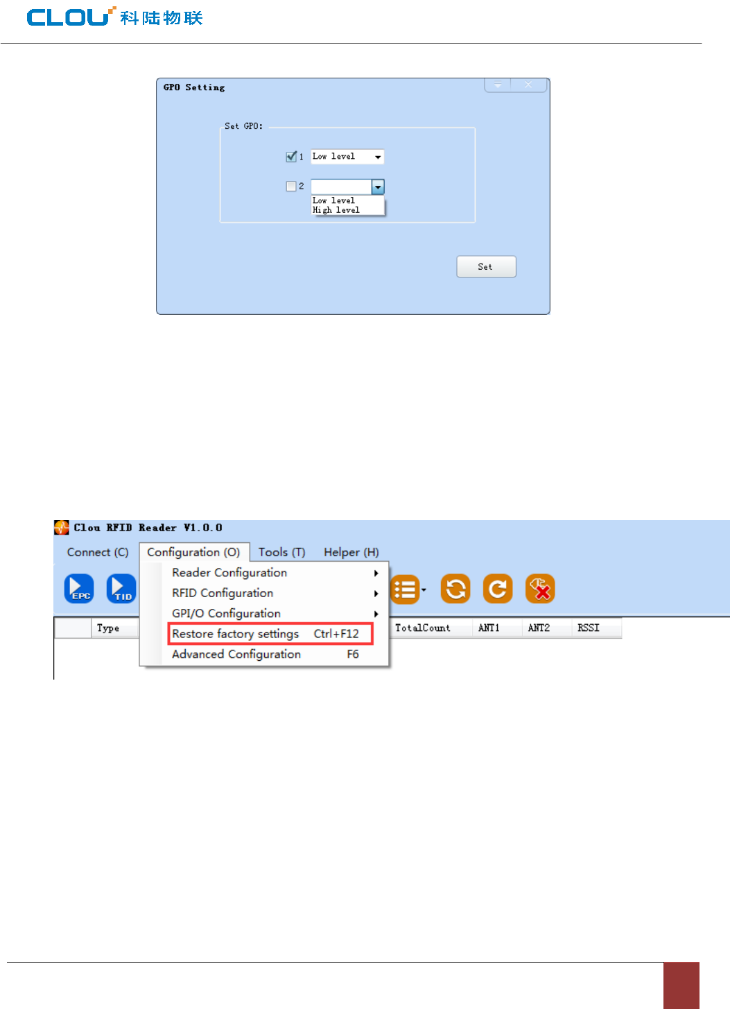
Picture 4-20 GPO configuration
CL7206C reader only support two way GPO output, that’s, “1” & “2”。
After high/low power level modification(setting) is finished, click “configuration” for setting operation.
Restore ex-factory default setting
In main UI, choose “configuration”Æ “restore ex-factory setting”, pop up dialog box as per picture 4-22.
Picture 4-22 restore ex-factory setting
Whatever way the reader is connected, when you click “restore ex-factory setting” button, all settings will
be restored to ex-factory setting.
4.4.10 Tool
Data export
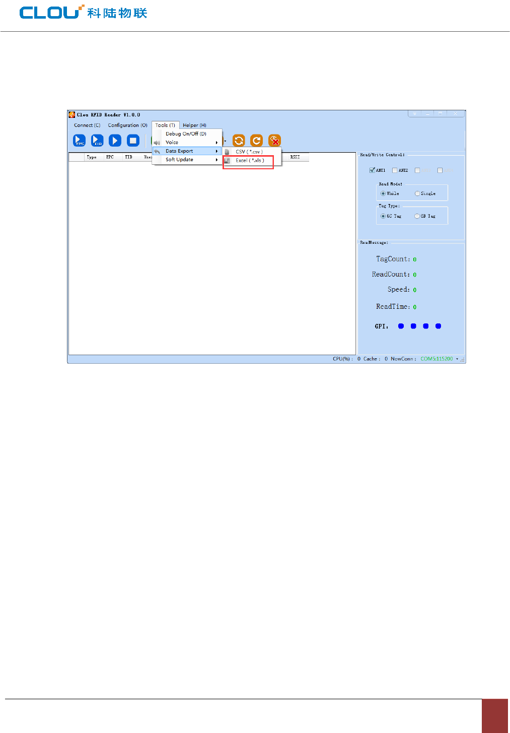
In main UI, choose “tool”Æ “data export”, the following dialog box pops up (picture 4-23), choose the
format to be exported.
Picture 4-23 Data export
All data tag can be exported at format .csv or xls.
Software upgrade
The reader supports online upgrade. Software upgrade support Baseband Software Upgrade & application
software upgrade(system application software). Choose “Tool” Æ “software upgrade”Æ “application softweare”.
Following dialog pops up (picture 4-24).
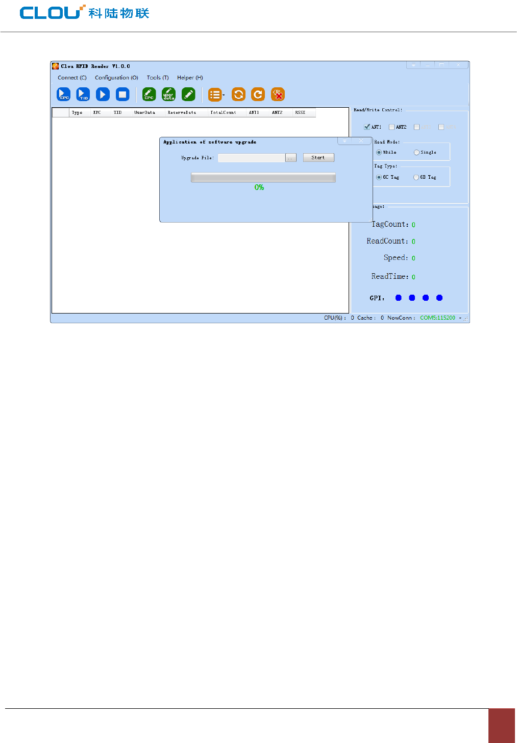
Picture 4-24 Application software upgrade
In the pull-down list of “upgrade file”, find the route of .bin upgrade file, click “start upgrade”, when the
progress bar displays 100% finished, the upgrade is finished and successful. Following dialog pops up, click
“confirm” for restart and enable it .
Baseband software upgrade process is same as above.

V, Common failure phenomenon
5.1 Daily maintenance
Check & ensure if the RF connector is fixed firmly☆
Check & ensure the screw that fixes reader & antenna is not loose.☆
Check & ensure the RF cable connection point skin is not peeling☆ off.
Check & ensure if the power supply cable is connected well. ☆
5.2 Common failure analysis & resolutions
Power supply abnormal☆
Check if the power supply is in normal status, if the AC power voltage is 100V~240V.
LED not light on when power supply ☆is connected
Check if communication is in normal status.
Serial port failed connection☆
Serial port cable is not connected or connection unstable.
Check if the serial port connection baud rate is correct.
Check if the serial port number is correct.
Netwo☆rk connection failure
The reader default IP address is: 192.168.1.116. Ensure PC IP address and reader IP address are in the
same network, for example “192.168.1.XXX” can be connected with reader. If you forgot reader IP address,
you can re-set it through RS232 to reader IP address.
☆ Can not read card
◇Check if RS232 or network cable is connected correctly. Unsecured connection may cause PC
command can not be passed to reader.
◇Check & ensure if the RF connector is fixed firmly or in normal status.
◇Check & ensure the card is not damaged.
☆ Wrong tag reading/writing
◇check if the reader type is configured correctly.
◇check if the tag type and reader is compatible.

◇check if the tag is in effective reading range.
◇check if there is EMI between readers or between reader & other device.
◇Check if tag is damaged.
☆Reader can not read tag.
◇Check if antenna number is set correctly. If antenna is connected with 1# RF port, then please
ensure to select 1# antenna in software interface.
◇Check if tag is damaged. If can not get ID number, you can use another reader to read this tag to
judge if this tag is damaged. If can not get data area, you need to check if the tag data area is
lock. Tags which are locked should be un-locked before any operations.
◇Check if tag is placed in effective reading range.
◇check if there is EMI between readers or between reader & other device.
For the problems which can not be solved locally, please contact CLOU aftersales for repairing.
5.3.Maintenance when not used for long time.
If you don’t use the reader for long time, please dis-connect the power supply, remove all cables, pack the
reader and accessories suitably, & store in well-ventilated conditions.
Chapter VI, Packaging, accessories, transportation & storage.
6.1 Packaging:
Packaging carton box size: 360 mm×360 mm×350mm
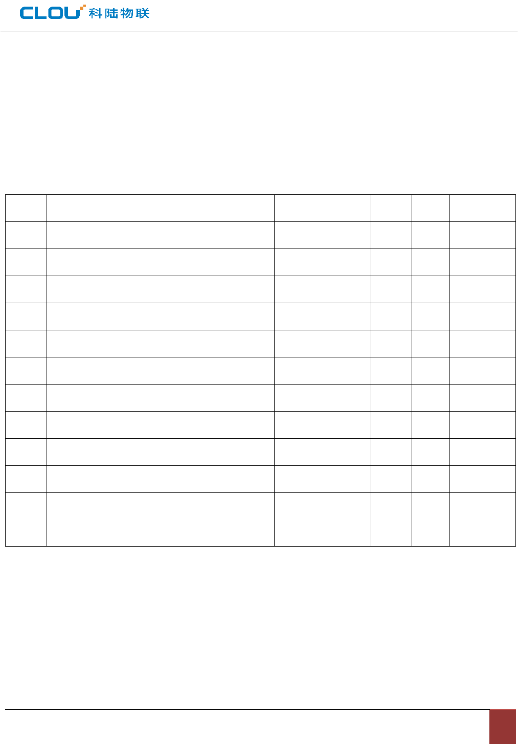
6.2 Accessories
Chart 6-1 Accessories list
6.3 Transport requirement.
☆During transport, please ensure the device is not sustain fierce collision, rain or corrosive chemicals.
6.4 Storage requirements
Long time storage should be made in following conditions: Temperature:-40℃~+85℃;Humidity:5%~
90%RH;
No. Name Material code unit Qty Remarks
1 Customized aviation cable (one for three) 20351000000552 1 unit 标配
2 Customized aviation external IO cable. 20351000000551 1 piece 标配
3 Power adapter 24V/2.5A 20109000000324 1 piece 标配
4 AC power cable 20350000000195 1 piece 标配
5 Network cable 20350000000188 1 piece 标配
6 RS232 connection cable 1800mm 20351000000478 1 piece 标配
7 hexagon socket cahead screwsGB70-85 M5*12 20400000000519 4 piece 标配
8 L shape installation bracket 20411000013135 1 piece 标配
9 hardware kits U shape bracket 20411000013136 2 piece 标配
10 9dBi antenna 20351000000035 1 unit Optional
11 Antenna feeder line SMA-K--TNC-J 50ohm
3meters
20351000000038 1 piece optional
DECLARATION OF CONFORMITY
Hereby,Shenzhen Clou IOT Technologies Co.,Ltd. declares that this Integrated Fixed
Reader product in compliance with the essential requirements and other relevant provisions
of Directive 1999/5/EC. A copy of the Declaration of Conformity can be found an Website:
http://www.clouiotech.com/
Testing standards:
EN 60950-1:2006 + A11:2009 +
A1:2010+A12:2011+A2:2013
EN 62311:2008
EN 301 489-1 V1.9.2(2011-09)
ETSI EN 301 489-3 V1.6.1(2013-08)
EN 302 208-1 V2.1.1: 2015-02
EN 302 208-2 V2.1.1: 2015-02
Manufacturer's Name: Shenzhen Clou IOT Technologies Co.,Ltd.
Integrated Fixed Reader
Trade Mark: N/A
Model number: CL7206B
Thisdevicewastestedfortypicalbody‐wornoperations.TocomplywithRFexposure
requirements,aminimumseparationdistanceof20cmmustbemaintainedbetween
theuser’s
bodyandthehandset,includingtheantenna.Third‐partybelt‐clips,holsters,and
similar
accessoriesusedbythisdeviceshouldnotcontainanymetalliccomponents.
Body‐worn

accessoriesthatdonotmeettheserequirementsmaynotcomplywithRFexposure
requirementsandshouldbeavoided.Useonlythesuppliedoranapprovedantenna.
Thisdeviceincompliancewiththeessentialrequirementsandotherrelevant
provisionsof
Directive1999/5/EC.Allessentialradiotestsuiteshavebeencarriedout.
1. CAUTION:RISKOFEXPLOSIONIFBATTERYISREPLACEDBYANINCORRECTTYPE.
DISPOSEOFUSEDBATTERIESACCORDINGTOTHEINSTRUCTIONS
2. ThedevicecomplieswithRFspecificationswhenthedeviceusedat20mmform
yourbody
Carefortheenvironment!
Mustnotbediscardedwithhouseholdwaste!
Thisproductcontainselectricalorelectroniccomponentsthatshouldberecycled.
Leavetheproductforrecyclingatthedesignatedstation,e.g.
thelocalauthority'srecyclingstation.

FCC WARNING
This device complies with part 15 of the FCC Rules. Operation is subject to the condition that this
device does not cause harmful interference (1) this device may not cause harmful interference,
and (2) this device must accept any interference received, including interference that may cause
undesired operation.
Any changes or modifications not expressly approved by the party responsible for compliance
could void the user's authority to operate the equipment.
NOTE: This equipment has been tested and found to comply with the limits for a Class B digital
device, pursuant to Part 15 of the FCC Rules. These limits are designed to provide reasonable
protection against harmful interference in a residential installation. This equipment generates,
uses and can radiate radio frequency energy and, if not installed and used in accordance with the
instructions, may cause harmful interference to radio communications. However, there is no
guarantee that interference will not occur in a particular installation.
If this equipment does cause harmful interference to radio or television reception,
which can be determined by turning the equipment off and on, the user is encouraged to try to
correct the interference by one or more of the following measures:
-- Reorient or relocate the receiving antenna.
-- Increase the separation between the equipment and receiver.
-- Connect the equipment into an outlet on a circuit different
from that to which the receiver is connected.
-- Consult the dealer or an experienced radio/TV technician for help.
To maintain compliance with FCC’s RF Exposure guidelines, This equipment should be installed and
operated with minimum distance between 20cm the radiator your body: Use only the supplied
antenna.
FCC ID: 2AKAGCLOUIOTCL7206B