Cobham Surveillance Segensworth NETNODEP4 Phase 4, Agile Mesh Netnode Module D1707 User Manual D17XX OEM INTEGRATION DOC V0 1

Cobham Surveillance Segensworth Phase 4, Agile Mesh Netnode Module D1707 D17XX OEM INTEGRATION DOC V0 1

Contents

D17XX OEM INTEGRATION DOC V0_1

D17XX OEM Integration v0.1    1 www.cobham.com/domo  Domo Limited doing business as Cobham Surveillance 1          V1.1v                        Mesh D17xx OEM Integration Document V0.1 24/04/2015
D17XX OEM Integration v0.1    2 www.cobham.com/domo  Domo Limited doing business as Cobham Surveillance Table of Contents Table of Contents ....................................................................................................... 2 Change History .......................................................................................................... 3 Introduction ............................................................................................................... 4 Hardware Overview ..................................................................................................... 5 PCB Variants ............................................................................................................. 7 Mechanical Design ...................................................................................................... 8 Functional Specification .............................................................................................. 9 Connector Pin outs ................................................................................................... 11 J1 Aux Power Out ............................................................................................................ 11 J2 Power Input ................................................................................................................. 11 J3 RS485 Serial Data Port ................................................................................................ 11 J4 Power to D550 Encoder ............................................................................................... 11 J5 1W Amplifier Power and Enable ................................................................................... 12 J6 RF Output .................................................................................................................... 12 J7 RS232 Serial Control ................................................................................................... 12 J8 BDM/JTAG (Reserved) ................................................................................................. 12 J9 RS232 to control D550 Encoder ................................................................................... 12 J10 Talkback Audio connections ...................................................................................... 12 J11 Connections to D550 Encoder ................................................................................... 13 J12 RS232 External Serial Data Ports ............................................................................... 13 J13 RTC Battery connector .............................................................................................. 13 J14 External 10/100 Base-T Ethernet Port ......................................................................... 13 J15 External Secondary 10/100 Base-T Ethernet Port ....................................................... 13 J16 USB connector (Not currently used) .......................................................................... 14 J17 LED Drive .................................................................................................................. 14 J18 Power over Ethernet .................................................................................................. 14 J19 Antenna B (Rx 1) ........................................................................................................ 14 J20 SD Card Management ................................................................................................ 14 J21 (not on board) ............................................................................................................ 15 J22 Antenna A (Tx Rx 0) ................................................................................................... 15 J23 (not on board) ............................................................................................................ 15 J24 RF Out ....................................................................................................................... 15 Mounting Considerations ........................................................................................... 16 Heat sinking ..................................................................................................................... 16 Connector clearance ........................................................................................................ 16 Turning On the System .............................................................................................. 17 1. Test Setup ............................................................................................................... 17 2. Initial Setup ............................................................................................................. 17 2.1 Setting unit type ............................................................................................ 17 2.2 Software updates ........................................................................................... 18 3. Verify the RF RX performance ................................................................................. 18 4. Verify the RF TX performance .................................................................................. 21 5. Spectrum Verification .............................................................................................. 22 6. Set RTC Clock ......................................................................................................... 22 7. Ethernet Video Streaming ........................................................................................ 23 8. Recording and Playback .......................................................................................... 23 9. Direct connection to PC ........................................................................................... 24 10. Serial RS232 Control ........................................................................................... 24 RS232 Control – General Principles ............................................................................ 24 Command Packet Structure ........................................................................................ 24 Reply Packet Structure ............................................................................................... 24 Control Commands ................................................................................................... 26
D17XX OEM Integration v0.1    3 www.cobham.com/domo  Domo Limited doing business as Cobham Surveillance Change History  Version Main Changes from Previous Version Edited By V0.1 First Draft CM 24/05/15
D17XX OEM Integration v0.1    4 www.cobham.com/domo  Domo Limited doing business as Cobham Surveillance Introduction  This document outlines the hardware integration for the D17XX IP Mesh baseband transceiver card.  The Cobham D17XX PCB is a digital diversity IP Mesh transceiver, designed specifically as the baseband and IP processing card for the Cobham IP Mesh phase 4 system.  The system allows wireless IP, digital video and audio transmission in mobile, urban and non-line-of-sight scenarios.  Equipped with Ethernet and serial control interfaces, the D17XX is easy to integrate into a larger system.  The key design criteria for this solution were:  Low power consumption  Small size  Ease of integration  Features include:  2.5MHz / 3MHz / 3.5MHz / 5MHz and 6MHz operating bandwidth modes  Two-way diversity Maximum Ratio Combining for fade and multipath elimination  Internal AES 128 / 256bit encryption (optional)  Twin IP interfaces  Multiple Serial interfaces  SMP connectors for reduced size and ease of connection  Optional Encoder offering very low delay video operation for real time applications  Interfaces for optional 1W amplifier  Talk-back Audio  Micro SD card for 32GB storage  Low power—typically ?W
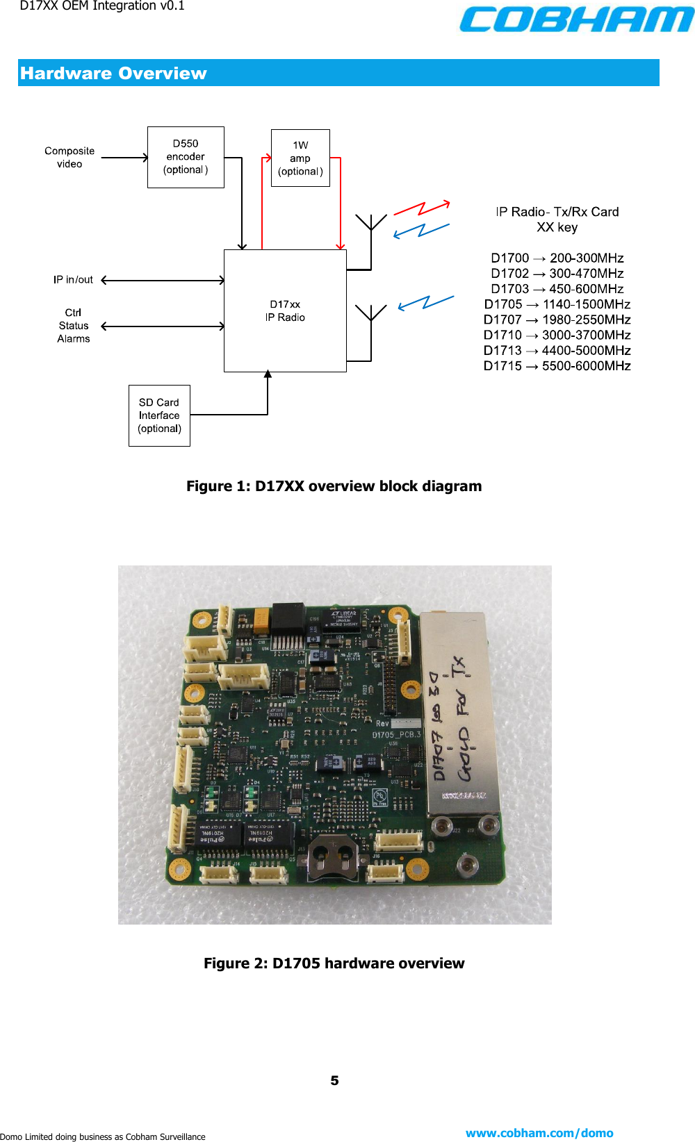
D17XX OEM Integration v0.1    5 www.cobham.com/domo  Domo Limited doing business as Cobham Surveillance Hardware Overview    Figure 1: D17XX overview block diagram      Figure 2: D1705 hardware overview
D17XX OEM Integration v0.1    6 www.cobham.com/domo  Domo Limited doing business as Cobham Surveillance   Features of the D17XX board are:  Kintex 7 FPGA and Coldfire microprocessor further reducing power consumption of the unit and increasing the processing power  Large SDRAM and Flash  Ethernet, RS485 and RS232 capability  Recording to SD card (when optional encoder is fitted)  Talkback Audio facility
D17XX OEM Integration v0.1    7 www.cobham.com/domo  Domo Limited doing business as Cobham Surveillance PCB Variants The frequency selection is provided by the choice of RF card and setting the unit type on the D17XX.          Table 1: D17XX variants (without screen cans)   A number of the boards are available in top-level assemblies.   Table 2: Sub-assemblies featuring D17XX parts (with screen cans)    Product No. Frequency [MHz] D1700 200 – 300 D1702 300 – 470 D1703 450 – 600 D1705 1140 – 1500 D1707 1980 – 2550 D1710 3000 – 3700 D1713 4400 – 5000 D1715 5500 – 6000 Cobham SA Number Description SA3024 D1707 OEM AGILE IP MESH, Mk4 (S Band 1.98-2.55GHz) Top Level Assembly SA3245 D1705 OEM AGILE IP MESH, Mk4 (L Band 1.14 - 1.5GHz) Top Level Assembly SA3334 D1705_D DSTAR OEM Agile IP MESH, MK4 (L Band) Top Level Assembly SA3453 D1703 OEM Agile IP MESH, MK4, 450-600MHz (UHF Band) Top Level Assembly SA3457 D1741 OEM Pavement RF Board (S Band 1.98-2.55GHz) Top Level Assembly
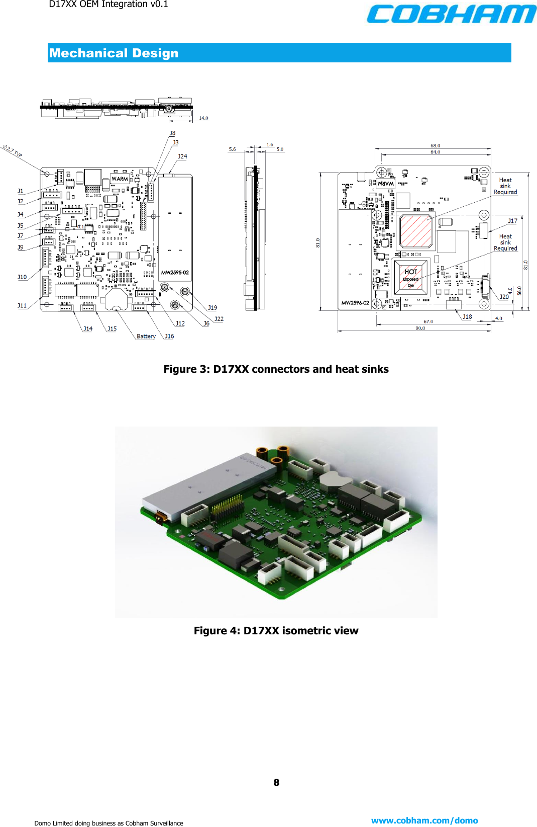
D17XX OEM Integration v0.1    8 www.cobham.com/domo  Domo Limited doing business as Cobham Surveillance Mechanical Design                  Figure 3: D17XX connectors and heat sinks     Figure 4: D17XX isometric view
D17XX OEM Integration v0.1    9 www.cobham.com/domo  Domo Limited doing business as Cobham Surveillance Functional Specification Interfaces RF Interfaces  (Antenna 1 and 2)    SMP  Power     JST J2  Ethernet 1    JST J14 Ethernet 2    JST J15 Control and misc. I/O JST J3 (RS485) and JST J12 (RS232) Camera (A/V)    Optional Card – D550     Typical range S-Band (1W)    Non-LoS light urban 500-700m     LoS 40km+  RF Interfaces Antenna 1    Switched transmit (100mW) & receive antenna Antenna 2    Receive only antenna Tuning step size    125kHz step Output power    +20 to -10dBm in 0.25dB steps (100mW variant)     +30 to 0dBm in 0.25dB steps (1W variant) Bandwidth    2.5, 3.0, 3.5, 5.0, 6.0MHz Mesh capacity    Up to 8 Mb/s Modulation    COFDM 360 carrier modulation Carrier Modulation    BPSK, QPSK or 16QAM (adaptive) FEC rate    FEC 1/2 Receive diversity    Maximum Ratio Combining Receive sensitivity    -98dBm for most robust mode  IP interface Primary & secondary  Ethernet electrical    100BaseT Ethernet IP address allocation  DHCP dynamic IP addressing Video and audio      Multicast VLC compatible streaming format    UDP & RTSP Support  Open Audio comms channel (shared voice channel) Multi-user audio  comms channel    Interface microphone level/headphone o/p Compression    G726 32kbit audio  Encryption Type    AES128 or AES256 (both optional)  GPS Dedicated GPS I/F    RS232/RS485
D17XX OEM Integration v0.1    10 www.cobham.com/domo  Domo Limited doing business as Cobham Surveillance  Data interface RS232/RS485 data     1K2 to 115K2 baud switchable     With UDP and TCP routing protocol  Control Local control    LEDs power and mesh status Remote control    Mission Commander PC application         Full control of all parameters in a map based application      Web browser control  Physical Mass    82g  Power DC input    12-14V Power consumed 1W  Up to 14W max  Environment Temperature rating    -10°C to +50°C  A/V input option Video input    Composite or SDI (selectable) Video format    525 or 625 (PAL or NTSC) Video encoding    MPEG4 Quality    Low/Medium/High (selectable) Video bit-rate    2.4Mb/s to 50kb/s (variable) Resolution    704, 576, 480 or 352 Frame rate    Self-selecting 30 to 2F/s Audio input    Line level or microphone level Audio sample freq.    48KHz Audio encoding    MPEG audio layer 1  Audio bit-rate    384 to 64kb/s  Store and forward options* Storage format    SD card interface (Secure Digital card) – optional Record options    Continuous or triggered Files download    From web browser interface (Milestone) AV clip size    30 seconds   * asterisk means what?
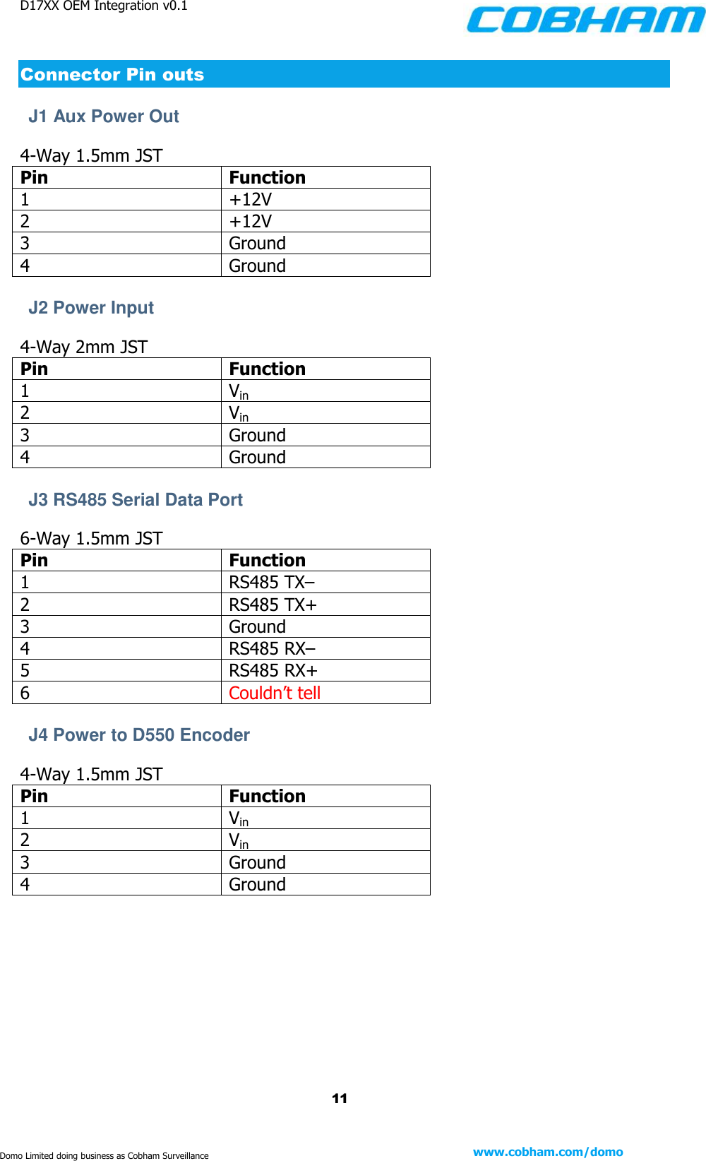
D17XX OEM Integration v0.1    11 www.cobham.com/domo  Domo Limited doing business as Cobham Surveillance Connector Pin outs J1 Aux Power Out   4-Way 1.5mm JST Pin Function 1 +12V 2 +12V 3 Ground 4 Ground  J2 Power Input 4-Way 2mm JST Pin Function 1 Vin 2 Vin 3 Ground 4 Ground  J3 RS485 Serial Data Port 6-Way 1.5mm JST Pin Function 1 RS485 TX– 2 RS485 TX+ 3 Ground 4 RS485 RX– 5 RS485 RX+ 6 Couldn’t tell  J4 Power to D550 Encoder   4-Way 1.5mm JST Pin Function 1 Vin 2 Vin 3 Ground 4 Ground
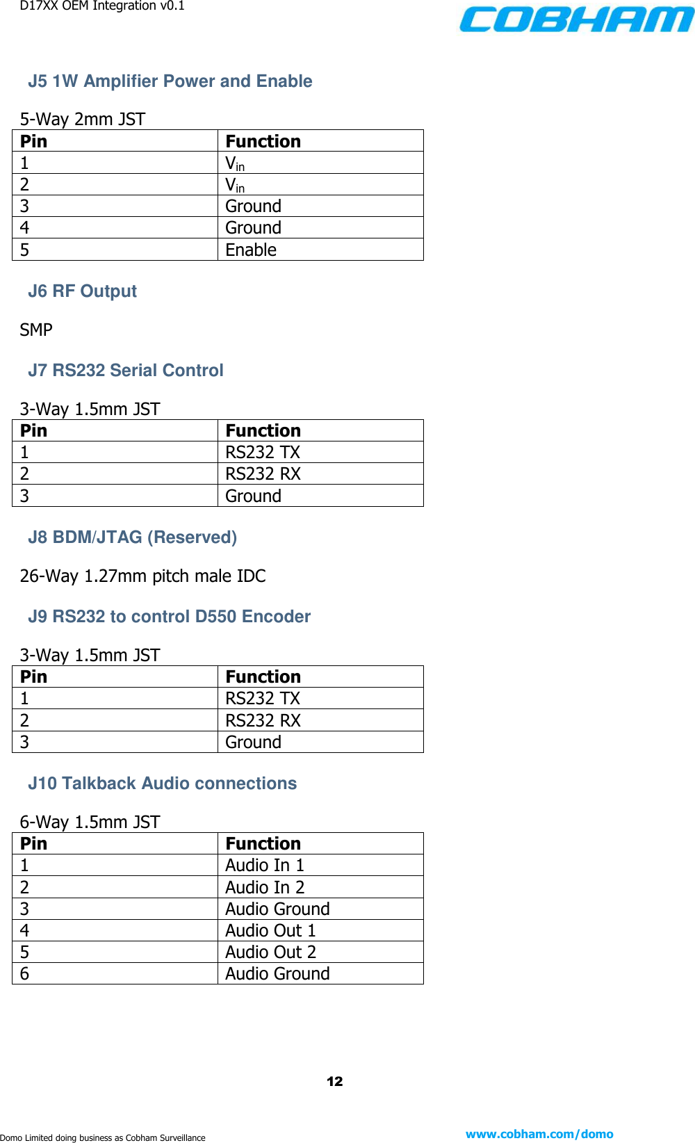
D17XX OEM Integration v0.1    12 www.cobham.com/domo  Domo Limited doing business as Cobham Surveillance  J5 1W Amplifier Power and Enable 5-Way 2mm JST Pin Function 1 Vin 2 Vin 3 Ground 4 Ground 5 Enable  J6 RF Output SMP  J7 RS232 Serial Control  3-Way 1.5mm JST Pin Function 1 RS232 TX 2 RS232 RX 3 Ground  J8 BDM/JTAG (Reserved) 26-Way 1.27mm pitch male IDC  J9 RS232 to control D550 Encoder  3-Way 1.5mm JST Pin Function 1 RS232 TX 2 RS232 RX 3 Ground  J10 Talkback Audio connections 6-Way 1.5mm JST Pin Function 1 Audio In 1 2 Audio In 2 3 Audio Ground 4 Audio Out 1 5 Audio Out 2 6 Audio Ground
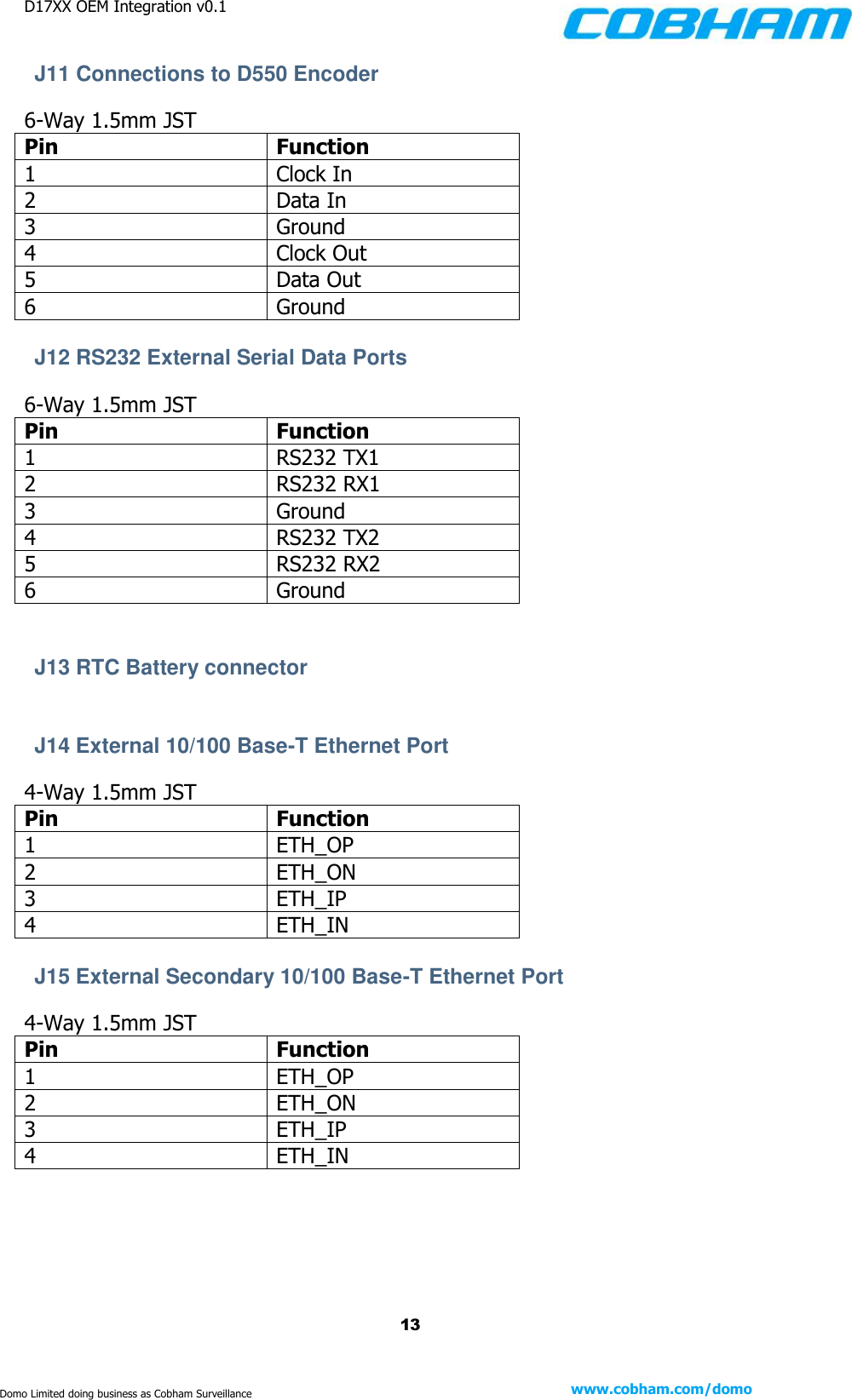
D17XX OEM Integration v0.1    13 www.cobham.com/domo  Domo Limited doing business as Cobham Surveillance J11 Connections to D550 Encoder 6-Way 1.5mm JST Pin Function 1 Clock In 2 Data In 3 Ground 4 Clock Out 5 Data Out 6 Ground  J12 RS232 External Serial Data Ports  6-Way 1.5mm JST Pin Function 1 RS232 TX1 2 RS232 RX1 3 Ground 4 RS232 TX2 5 RS232 RX2 6 Ground   J13 RTC Battery connector   J14 External 10/100 Base-T Ethernet Port  4-Way 1.5mm JST Pin Function 1 ETH_OP 2 ETH_ON 3 ETH_IP 4 ETH_IN  J15 External Secondary 10/100 Base-T Ethernet Port  4-Way 1.5mm JST Pin Function 1 ETH_OP 2 ETH_ON 3 ETH_IP 4 ETH_IN
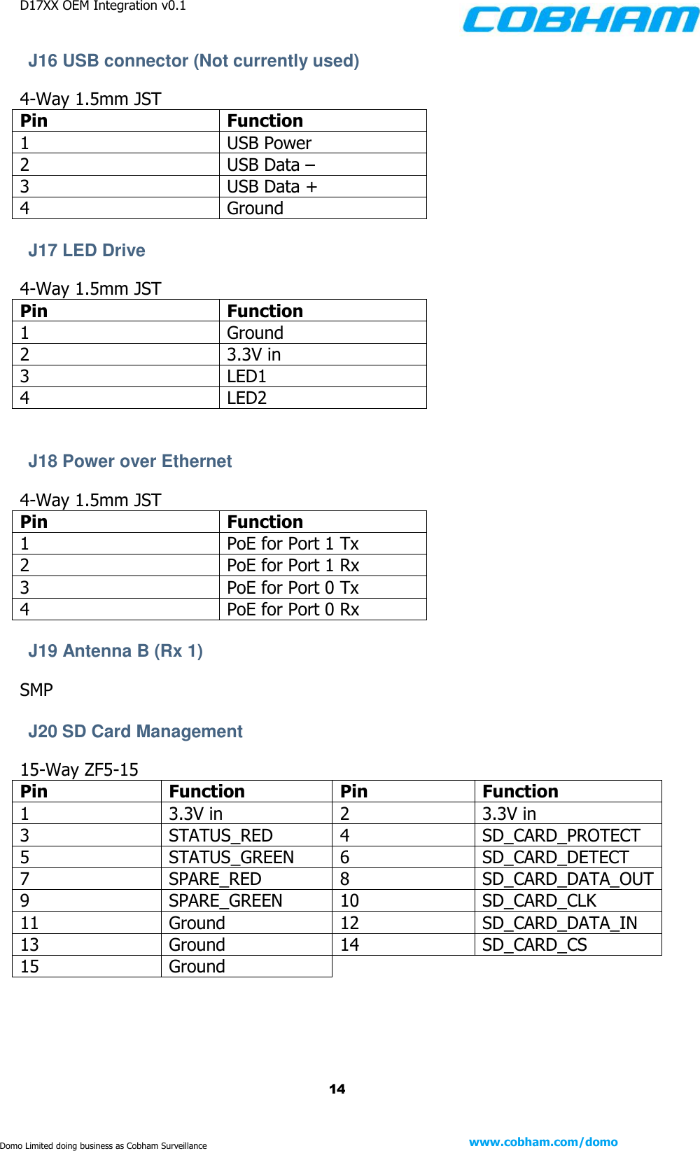
D17XX OEM Integration v0.1    14 www.cobham.com/domo  Domo Limited doing business as Cobham Surveillance J16 USB connector (Not currently used) 4-Way 1.5mm JST Pin Function 1 USB Power 2 USB Data – 3 USB Data + 4 Ground  J17 LED Drive  4-Way 1.5mm JST Pin Function 1 Ground 2 3.3V in 3 LED1 4 LED2   J18 Power over Ethernet 4-Way 1.5mm JST Pin Function 1 PoE for Port 1 Tx 2 PoE for Port 1 Rx 3 PoE for Port 0 Tx 4 PoE for Port 0 Rx  J19 Antenna B (Rx 1)  SMP  J20 SD Card Management 15-Way ZF5-15 Pin Function Pin Function 1 3.3V in 2 3.3V in 3 STATUS_RED 4 SD_CARD_PROTECT 5 STATUS_GREEN 6 SD_CARD_DETECT 7 SPARE_RED 8 SD_CARD_DATA_OUT 9 SPARE_GREEN 10 SD_CARD_CLK 11 Ground 12 SD_CARD_DATA_IN 13 Ground 14 SD_CARD_CS 15 Ground
D17XX OEM Integration v0.1    15 www.cobham.com/domo  Domo Limited doing business as Cobham Surveillance J21 (not on board) J22 Antenna A (Tx Rx 0) SMP  J23 (not on board) J24 RF Out SMP
D17XX OEM Integration v0.1    16 www.cobham.com/domo  Domo Limited doing business as Cobham Surveillance Mounting Considerations  The following steps should be followed when mounting the D17XX PCB.  Note: Should these guidelines be ignored, performance may suffer and the board may be damaged permanently. Heat sinking The Microprocessor (U28D17XX) and FPGA (U3D17XX) require thorough heat sinking to a metal mounting plate, as indicated in Figure 3. Failure to install such provisions will damage both components.  Connector clearance Provision should be made for any ribbon cables as they cannot be folded in the first 10mm at either end of termination. The same is true for SMA connectors. All JST’s are a similar height to the Tin cans on each card.
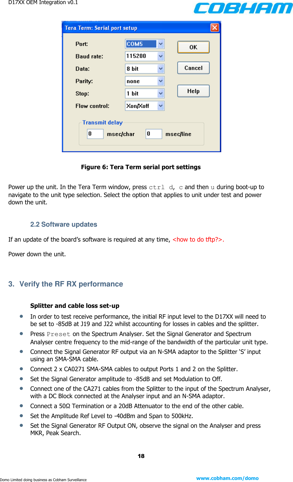
D17XX OEM Integration v0.1    17 www.cobham.com/domo  Domo Limited doing business as Cobham Surveillance Turning On the System [Extract taken from the D1705 TP v1.1 and as such, Tera Term figures will refer to this variant]  1.  Test Setup Connect the following cables to the D17XX PCB, as shown in Figure 5.   Power Cable from external PSU to J2 o Set supply to 12V 1.5A  CA0364 to J14 (Connect Ethernet cable to CA0364 – not shown)  CA0001/CA0149 to J12   If D550 encoder is desired (not shown):  o D55x Custom loom to J4, J9, J11  o CA0186 to J7 on D576   Figure 5: Initial setup cabling  2.  Initial Setup 2.1 Setting unit type Launch a Tera Term window and configure a serial port connection with the settings shown in Figure 6. Note that the port number will depend on your hardware setup and may well vary from that shown below.
D17XX OEM Integration v0.1    18 www.cobham.com/domo  Domo Limited doing business as Cobham Surveillance   Figure 6: Tera Term serial port settings  Power up the unit. In the Tera Term window, press ctrl d, c and then u during boot-up to navigate to the unit type selection. Select the option that applies to unit under test and power down the unit.   2.2 Software updates If an update of the board’s software is required at any time, <how to do tftp?>.  Power down the unit.   3.  Verify the RF RX performance  Splitter and cable loss set-up  In order to test receive performance, the initial RF input level to the D17XX will need to be set to -85dB at J19 and J22 whilst accounting for losses in cables and the splitter.  Press Preset on the Spectrum Analyser. Set the Signal Generator and Spectrum Analyser centre frequency to the mid-range of the bandwidth of the particular unit type.  Connect the Signal Generator RF output via an N-SMA adaptor to the Splitter ‘S’ input using an SMA-SMA cable.   Connect 2 x CA0271 SMA-SMA cables to output Ports 1 and 2 on the Splitter.   Set the Signal Generator amplitude to -85dB and set Modulation to Off.  Connect one of the CA271 cables from the Splitter to the input of the Spectrum Analyser, with a DC Block connected at the Analyser input and an N-SMA adaptor.   Connect a 50Ω Termination or a 20dB Attenuator to the end of the other cable.  Set the Amplitude Ref Level to -40dBm and Span to 500kHz.  Set the Signal Generator RF Output ON, observe the signal on the Analyser and press MKR, Peak Search.
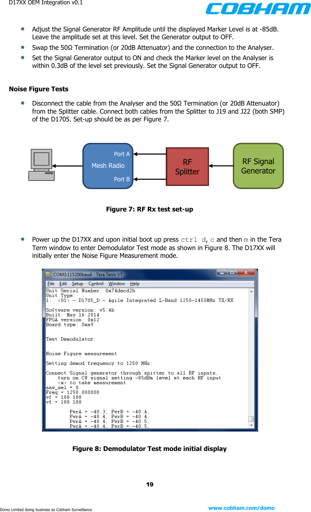
D17XX OEM Integration v0.1    19 www.cobham.com/domo  Domo Limited doing business as Cobham Surveillance  Adjust the Signal Generator RF Amplitude until the displayed Marker Level is at -85dB. Leave the amplitude set at this level. Set the Generator output to OFF.  Swap the 50Ω Termination (or 20dB Attenuator) and the connection to the Analyser.  Set the Signal Generator output to ON and check the Marker level on the Analyser is within 0.3dB of the level set previously. Set the Signal Generator output to OFF.  Noise Figure Tests  Disconnect the cable from the Analyser and the 50Ω Termination (or 20dB Attenuator) from the Splitter cable. Connect both cables from the Splitter to J19 and J22 (both SMP) of the D1705. Set-up should be as per Figure 7.           Figure 7: RF Rx test set-up    Power up the D17XX and upon initial boot up press ctrl d, c and then m in the Tera Term window to enter Demodulator Test mode as shown in Figure 8. The D17XX will initially enter the Noise Figure Measurement mode.    Figure 8: Demodulator Test mode initial display    Port B Mesh Radio Port A RF Splitter RF Signal Generator
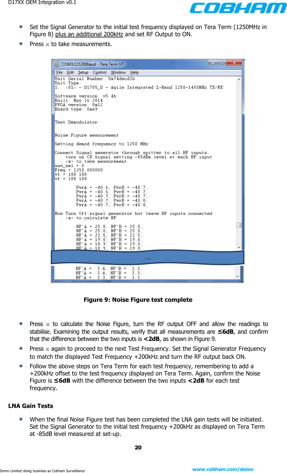
D17XX OEM Integration v0.1    20 www.cobham.com/domo  Domo Limited doing business as Cobham Surveillance  Set the Signal Generator to the initial test frequency displayed on Tera Term (1250MHz in Figure 8) plus an additional 200kHz and set RF Output to ON.  Press x to take measurements.       Figure 9: Noise Figure test complete   Press  x  to  calculate  the  Noise  Figure,  turn  the  RF  output  OFF  and  allow  the  readings  to stabilise. Examining the output results, verify that all measurements are ≤6dB, and confirm that the difference between the two inputs is <2dB, as shown in Figure 9.  Press x again to proceed to the next Test Frequency. Set the Signal Generator Frequency to match the displayed Test Frequency +200kHz and turn the RF output back ON.  Follow the above steps on Tera Term for each test frequency, remembering to add a +200kHz offset to the test frequency displayed on Tera Term. Again, confirm the Noise Figure is ≤6dB with the difference between the two inputs <2dB for each test frequency.  LNA Gain Tests  When the final Noise Figure test has been completed the LNA gain tests will be initiated. Set the Signal Generator to the initial test frequency +200kHz as displayed on Tera Term at -85dB level measured at set-up. …..
D17XX OEM Integration v0.1    21 www.cobham.com/domo  Domo Limited doing business as Cobham Surveillance  Set the RF output of the Signal Generator to ON and verify the gain lies within the limits laid out in Table 3.             Table 3: LNA gain limits   Press x to continue through to the next gain frequency, remembering to add 200kHz to all indicated test frequencies on the Signal Generator and refer to Table 3 to verify the limits.  Continue this process for all gain test frequencies. Press x to complete the LNA Gain Tests and turn the Signal Generator RF output OFF.  4.  Verify the RF TX performance  Plug in the RF cable to a Power Meter via the RF output (J24) on the D17XX.   Cycle the power on the unit and upon initial boot up ctrl d, c and then t to enter power test mode, as shown in Figure 10.   Figure 10: Power calibration display in Tera Term Frequency [MHz] Max Gain [dB] Min Gain [dB] 1250 -22 -27 1340 -19 -24 1400 -20.5 -25.5 1450 -23 -28
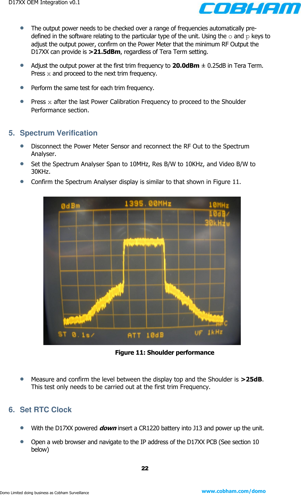
D17XX OEM Integration v0.1    22 www.cobham.com/domo  Domo Limited doing business as Cobham Surveillance  The output power needs to be checked over a range of frequencies automatically pre-defined in the software relating to the particular type of the unit. Using the o and p keys to adjust the output power, confirm on the Power Meter that the minimum RF Output the D17XX can provide is >21.5dBm, regardless of Tera Term setting.   Adjust the output power at the first trim frequency to 20.0dBm ± 0.25dB in Tera Term. Press x and proceed to the next trim frequency.  Perform the same test for each trim frequency.  Press x after the last Power Calibration Frequency to proceed to the Shoulder Performance section.  5.  Spectrum Verification  Disconnect the Power Meter Sensor and reconnect the RF Out to the Spectrum Analyser.  Set the Spectrum Analyser Span to 10MHz, Res B/W to 10KHz, and Video B/W to 30KHz.  Confirm the Spectrum Analyser display is similar to that shown in Figure 11.   Figure 11: Shoulder performance   Measure and confirm the level between the display top and the Shoulder is >25dB. This test only needs to be carried out at the first trim Frequency.  6.  Set RTC Clock   With the D17XX powered down insert a CR1220 battery into J13 and power up the unit.  Open a web browser and navigate to the IP address of the D17XX PCB (See section 10 below)
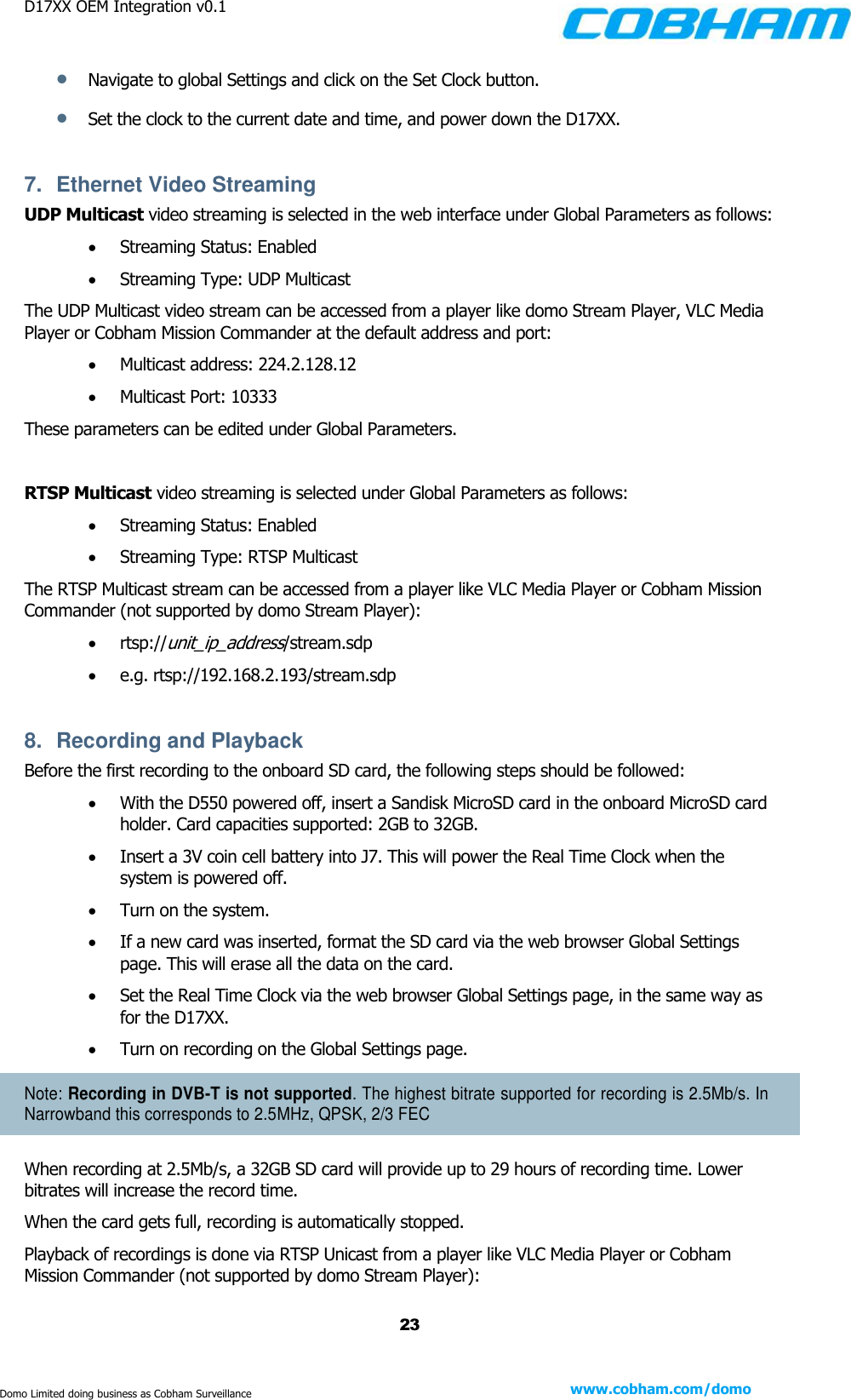
D17XX OEM Integration v0.1    23 www.cobham.com/domo  Domo Limited doing business as Cobham Surveillance  Navigate to global Settings and click on the Set Clock button.  Set the clock to the current date and time, and power down the D17XX.  7.  Ethernet Video Streaming  UDP Multicast video streaming is selected in the web interface under Global Parameters as follows:  Streaming Status: Enabled  Streaming Type: UDP Multicast The UDP Multicast video stream can be accessed from a player like domo Stream Player, VLC Media Player or Cobham Mission Commander at the default address and port:   Multicast address: 224.2.128.12  Multicast Port: 10333 These parameters can be edited under Global Parameters.  RTSP Multicast video streaming is selected under Global Parameters as follows:  Streaming Status: Enabled  Streaming Type: RTSP Multicast The RTSP Multicast stream can be accessed from a player like VLC Media Player or Cobham Mission Commander (not supported by domo Stream Player):  rtsp://unit_ip_address/stream.sdp  e.g. rtsp://192.168.2.193/stream.sdp  8.  Recording and Playback Before the first recording to the onboard SD card, the following steps should be followed:  With the D550 powered off, insert a Sandisk MicroSD card in the onboard MicroSD card holder. Card capacities supported: 2GB to 32GB.  Insert a 3V coin cell battery into J7. This will power the Real Time Clock when the system is powered off.  Turn on the system.   If a new card was inserted, format the SD card via the web browser Global Settings page. This will erase all the data on the card.  Set the Real Time Clock via the web browser Global Settings page, in the same way as for the D17XX.  Turn on recording on the Global Settings page. Note: Recording in DVB-T is not supported. The highest bitrate supported for recording is 2.5Mb/s. In Narrowband this corresponds to 2.5MHz, QPSK, 2/3 FEC When recording at 2.5Mb/s, a 32GB SD card will provide up to 29 hours of recording time. Lower bitrates will increase the record time. When the card gets full, recording is automatically stopped. Playback of recordings is done via RTSP Unicast from a player like VLC Media Player or Cobham Mission Commander (not supported by domo Stream Player):
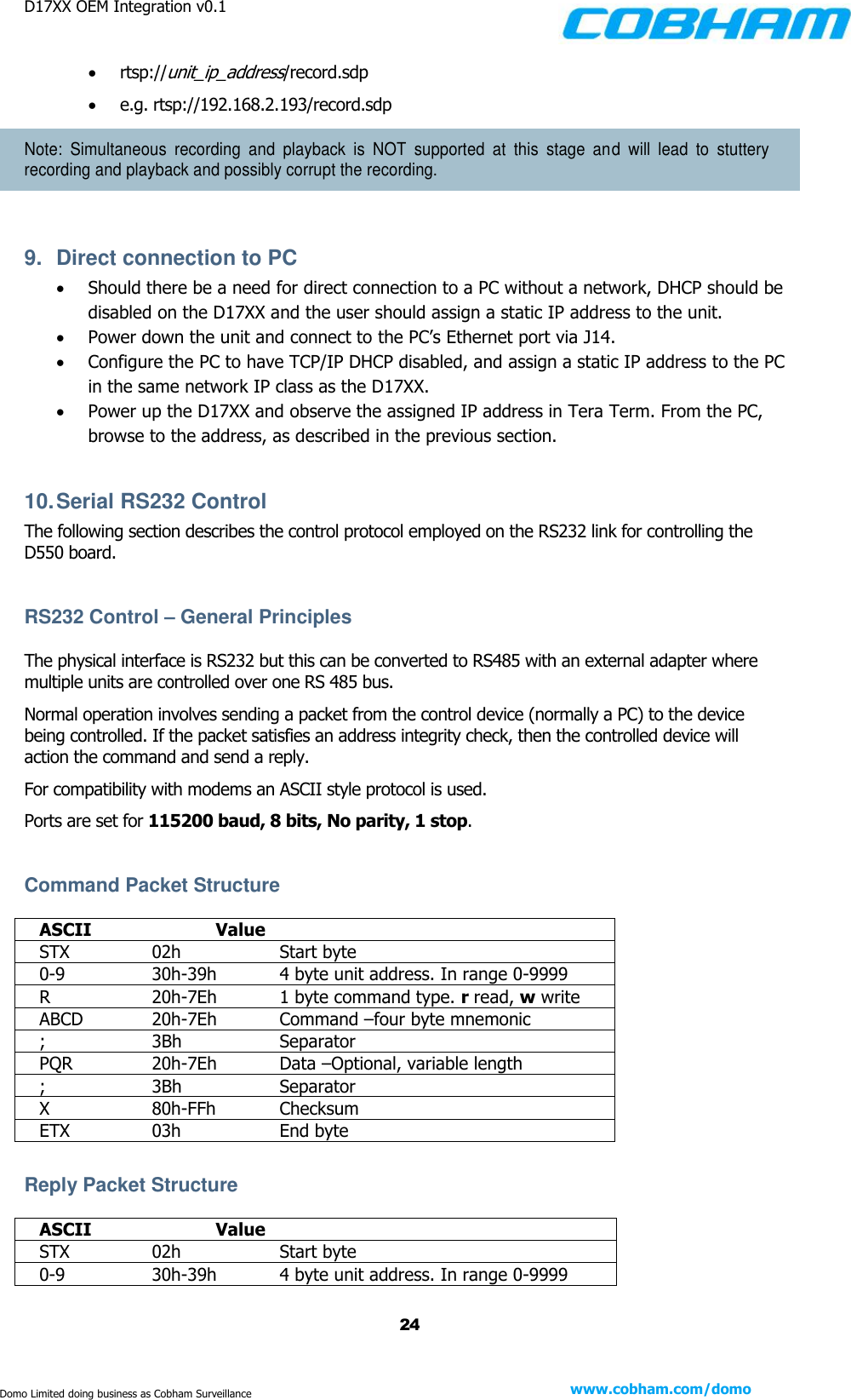
D17XX OEM Integration v0.1    24 www.cobham.com/domo  Domo Limited doing business as Cobham Surveillance  rtsp://unit_ip_address/record.sdp  e.g. rtsp://192.168.2.193/record.sdp Note:  Simultaneous  recording  and  playback  is  NOT  supported  at  this  stage  and  will  lead  to  stuttery recording and playback and possibly corrupt the recording.  9.  Direct connection to PC  Should there be a need for direct connection to a PC without a network, DHCP should be disabled on the D17XX and the user should assign a static IP address to the unit.  Power down the unit and connect to the PC’s Ethernet port via J14.  Configure the PC to have TCP/IP DHCP disabled, and assign a static IP address to the PC in the same network IP class as the D17XX.  Power up the D17XX and observe the assigned IP address in Tera Term. From the PC, browse to the address, as described in the previous section.  10. Serial RS232 Control The following section describes the control protocol employed on the RS232 link for controlling the D550 board.  RS232 Control – General Principles The physical interface is RS232 but this can be converted to RS485 with an external adapter where multiple units are controlled over one RS 485 bus. Normal operation involves sending a packet from the control device (normally a PC) to the device being controlled. If the packet satisfies an address integrity check, then the controlled device will action the command and send a reply. For compatibility with modems an ASCII style protocol is used.  Ports are set for 115200 baud, 8 bits, No parity, 1 stop.  Command Packet Structure  ASCII    Value STX    02h    Start byte 0-9    30h-39h   4 byte unit address. In range 0-9999 R    20h-7Eh  1 byte command type. r read, w write  ABCD   20h-7Eh  Command –four byte mnemonic  ;    3Bh    Separator PQR    20h-7Eh  Data –Optional, variable length ;    3Bh    Separator X    80h-FFh  Checksum ETX    03h    End byte  Reply Packet Structure  ASCII    Value STX    02h    Start byte 0-9    30h-39h   4 byte unit address. In range 0-9999
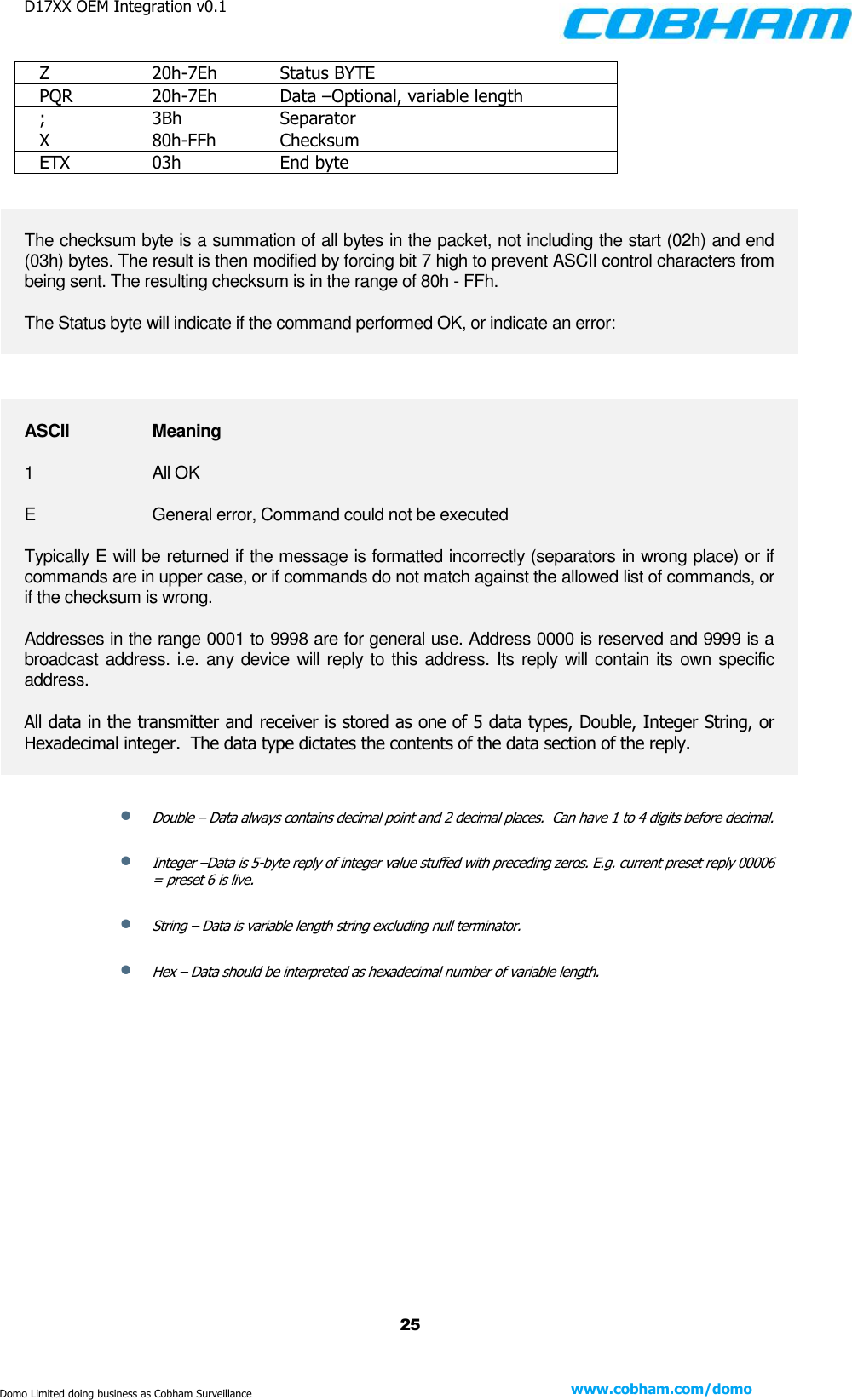
D17XX OEM Integration v0.1    25 www.cobham.com/domo  Domo Limited doing business as Cobham Surveillance Z    20h-7Eh   Status BYTE PQR    20h-7Eh  Data –Optional, variable length ;    3Bh    Separator X    80h-FFh  Checksum ETX    03h    End byte  The checksum byte is a summation of all bytes in the packet, not including the start (02h) and end (03h) bytes. The result is then modified by forcing bit 7 high to prevent ASCII control characters from being sent. The resulting checksum is in the range of 80h - FFh. The Status byte will indicate if the command performed OK, or indicate an error:  ASCII    Meaning 1    All OK E    General error, Command could not be executed Typically E will be returned if the message is formatted incorrectly (separators in wrong place) or if commands are in upper case, or if commands do not match against the allowed list of commands, or if the checksum is wrong. Addresses in the range 0001 to 9998 are for general use. Address 0000 is reserved and 9999 is a broadcast address. i.e. any device will reply to this address. Its reply will contain its own specific address. All data in the transmitter and receiver is stored as one of 5 data types, Double, Integer String, or Hexadecimal integer.  The data type dictates the contents of the data section of the reply.  Double – Data always contains decimal point and 2 decimal places.  Can have 1 to 4 digits before decimal.  Integer –Data is 5-byte reply of integer value stuffed with preceding zeros. E.g. current preset reply 00006 = preset 6 is live.  String – Data is variable length string excluding null terminator.  Hex – Data should be interpreted as hexadecimal number of variable length.
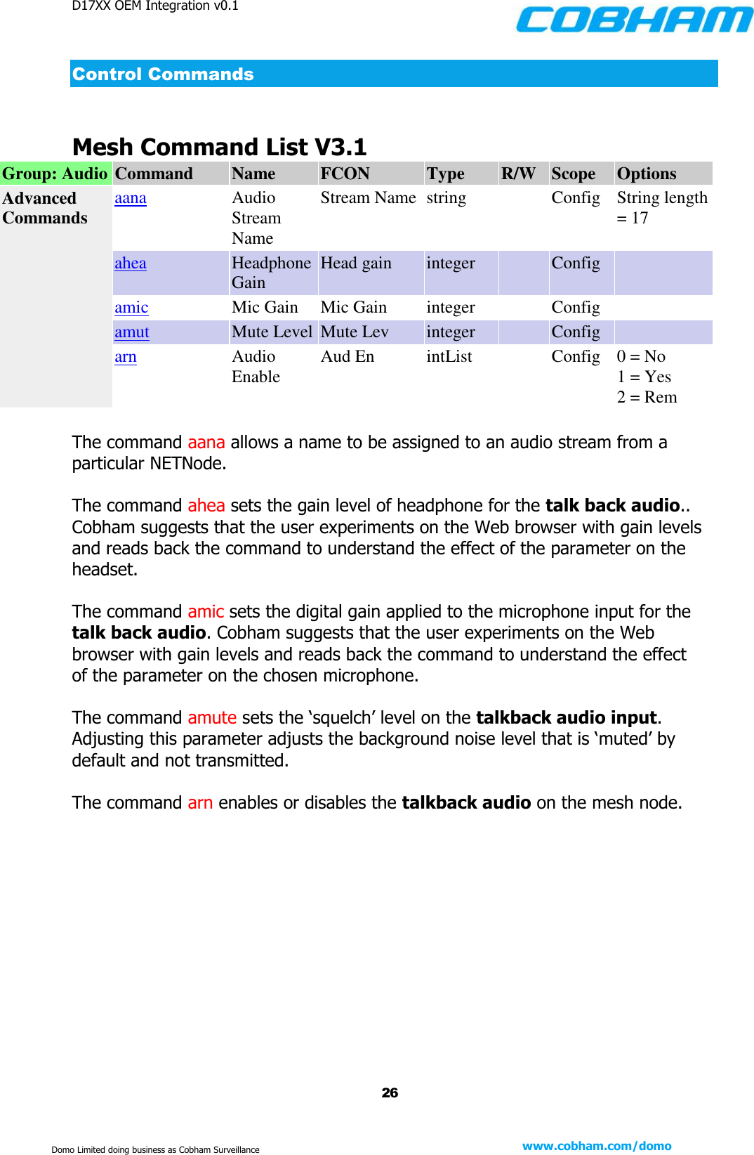
D17XX OEM Integration v0.1    26 www.cobham.com/domo  Domo Limited doing business as Cobham Surveillance Control Commands  Mesh Command List V3.1 Group: Audio Command Name FCON Type R/W Scope Options Advanced Commands aana Audio Stream Name Stream Name string  Config String length = 17 ahea Headphone Gain Head gain integer  Config  amic Mic Gain Mic Gain integer  Config  amut Mute Level Mute Lev integer  Config  arn Audio Enable Aud En intList  Config 0 = No 1 = Yes 2 = Rem  The command aana allows a name to be assigned to an audio stream from a particular NETNode.  The command ahea sets the gain level of headphone for the talk back audio.. Cobham suggests that the user experiments on the Web browser with gain levels and reads back the command to understand the effect of the parameter on the headset.  The command amic sets the digital gain applied to the microphone input for the talk back audio. Cobham suggests that the user experiments on the Web browser with gain levels and reads back the command to understand the effect of the parameter on the chosen microphone.  The command amute sets the ‘squelch’ level on the talkback audio input. Adjusting this parameter adjusts the background noise level that is ‘muted’ by default and not transmitted.   The command arn enables or disables the talkback audio on the mesh node.
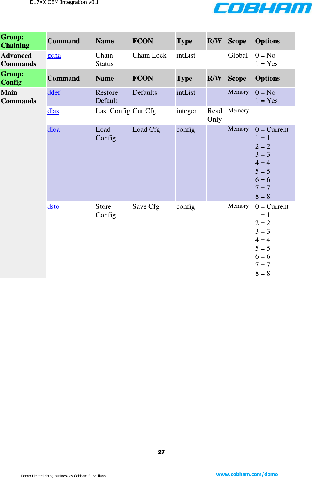
D17XX OEM Integration v0.1    27 www.cobham.com/domo  Domo Limited doing business as Cobham Surveillance         Group: Chaining Command Name FCON Type R/W Scope Options Advanced Commands gcha Chain Status Chain Lock intList  Global 0 = No 1 = Yes Group: Config Command Name FCON Type R/W Scope Options Main Commands ddef Restore Default Defaults intList  Memory 0 = No 1 = Yes dlas Last Config Cur Cfg integer Read Only Memory  dloa Load Config Load Cfg config  Memory 0 = Current 1 = 1 2 = 2 3 = 3 4 = 4 5 = 5 6 = 6 7 = 7 8 = 8 dsto Store Config Save Cfg config  Memory 0 = Current 1 = 1 2 = 2 3 = 3 4 = 4 5 = 5 6 = 6 7 = 7 8 = 8
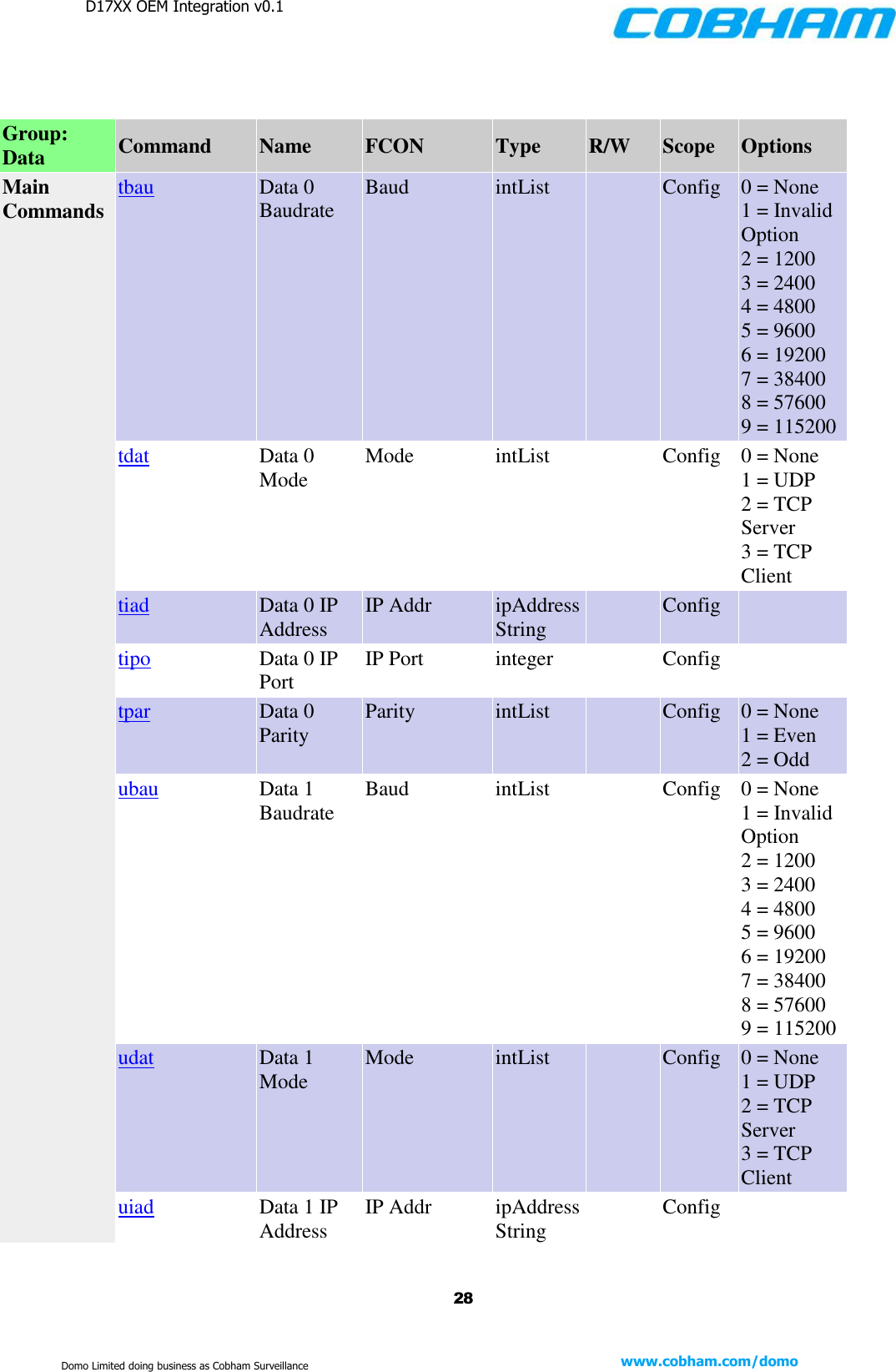
D17XX OEM Integration v0.1    28 www.cobham.com/domo  Domo Limited doing business as Cobham Surveillance          Group: Data Command Name FCON Type R/W Scope Options Main Commands tbau Data 0 Baudrate Baud intList  Config 0 = None 1 = Invalid Option 2 = 1200 3 = 2400 4 = 4800 5 = 9600 6 = 19200 7 = 38400 8 = 57600 9 = 115200 tdat Data 0 Mode Mode intList  Config 0 = None 1 = UDP 2 = TCP Server 3 = TCP Client tiad Data 0 IP Address IP Addr ipAddressString  Config  tipo Data 0 IP Port IP Port integer  Config  tpar Data 0 Parity Parity intList  Config 0 = None 1 = Even 2 = Odd ubau Data 1 Baudrate Baud intList  Config 0 = None 1 = Invalid Option 2 = 1200 3 = 2400 4 = 4800 5 = 9600 6 = 19200 7 = 38400 8 = 57600 9 = 115200 udat Data 1 Mode Mode intList  Config 0 = None 1 = UDP 2 = TCP Server 3 = TCP Client uiad Data 1 IP Address IP Addr ipAddressString  Config
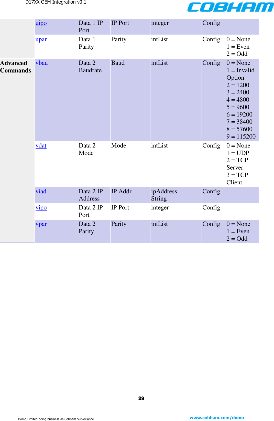
D17XX OEM Integration v0.1    29 www.cobham.com/domo  Domo Limited doing business as Cobham Surveillance uipo Data 1 IP Port IP Port integer  Config  upar Data 1 Parity Parity intList  Config 0 = None 1 = Even 2 = Odd Advanced Commands vbau Data 2 Baudrate Baud intList  Config 0 = None 1 = Invalid Option 2 = 1200 3 = 2400 4 = 4800 5 = 9600 6 = 19200 7 = 38400 8 = 57600 9 = 115200 vdat Data 2 Mode Mode intList  Config 0 = None 1 = UDP 2 = TCP Server 3 = TCP Client viad Data 2 IP Address IP Addr ipAddressString  Config  vipo Data 2 IP Port IP Port integer  Config  vpar Data 2 Parity Parity intList  Config 0 = None 1 = Even 2 = Odd
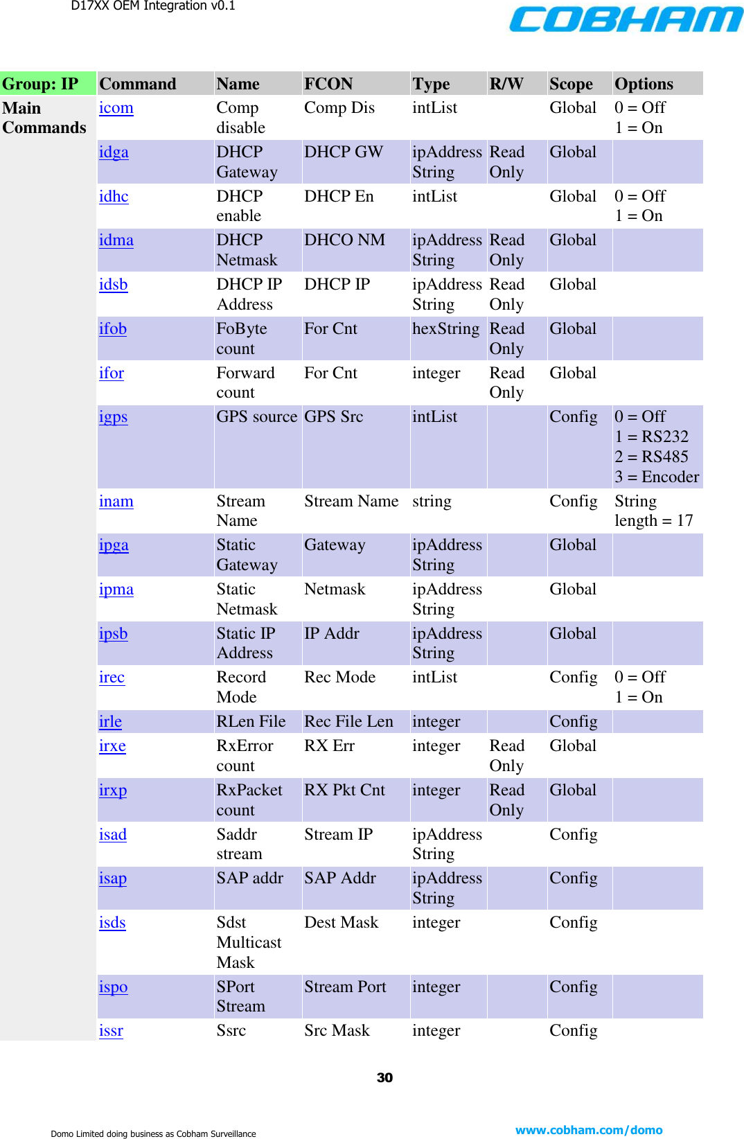
D17XX OEM Integration v0.1    30 www.cobham.com/domo  Domo Limited doing business as Cobham Surveillance  Group: IP Command Name FCON Type R/W Scope Options Main Commands icom Comp disable Comp Dis intList  Global 0 = Off 1 = On idga DHCP Gateway DHCP GW ipAddressString Read Only Global  idhc DHCP enable DHCP En intList  Global 0 = Off 1 = On idma DHCP Netmask DHCO NM ipAddressString Read Only Global  idsb DHCP IP Address DHCP IP ipAddressString Read Only Global  ifob FoByte count For Cnt hexString Read Only Global  ifor Forward count For Cnt integer Read Only Global  igps GPS source GPS Src intList  Config 0 = Off 1 = RS232 2 = RS485 3 = Encoder inam Stream Name Stream Name string  Config String length = 17 ipga Static Gateway Gateway ipAddressString  Global  ipma Static Netmask Netmask ipAddressString  Global  ipsb Static IP Address IP Addr ipAddressString  Global  irec Record Mode Rec Mode intList  Config 0 = Off 1 = On irle RLen File Rec File Len integer  Config  irxe RxError count RX Err integer Read Only Global  irxp RxPacket count RX Pkt Cnt integer Read Only Global  isad Saddr stream Stream IP ipAddressString  Config  isap SAP addr SAP Addr ipAddressString  Config  isds Sdst Multicast Mask Dest Mask integer  Config  ispo SPort Stream Stream Port integer  Config  issr Ssrc Src Mask integer  Config
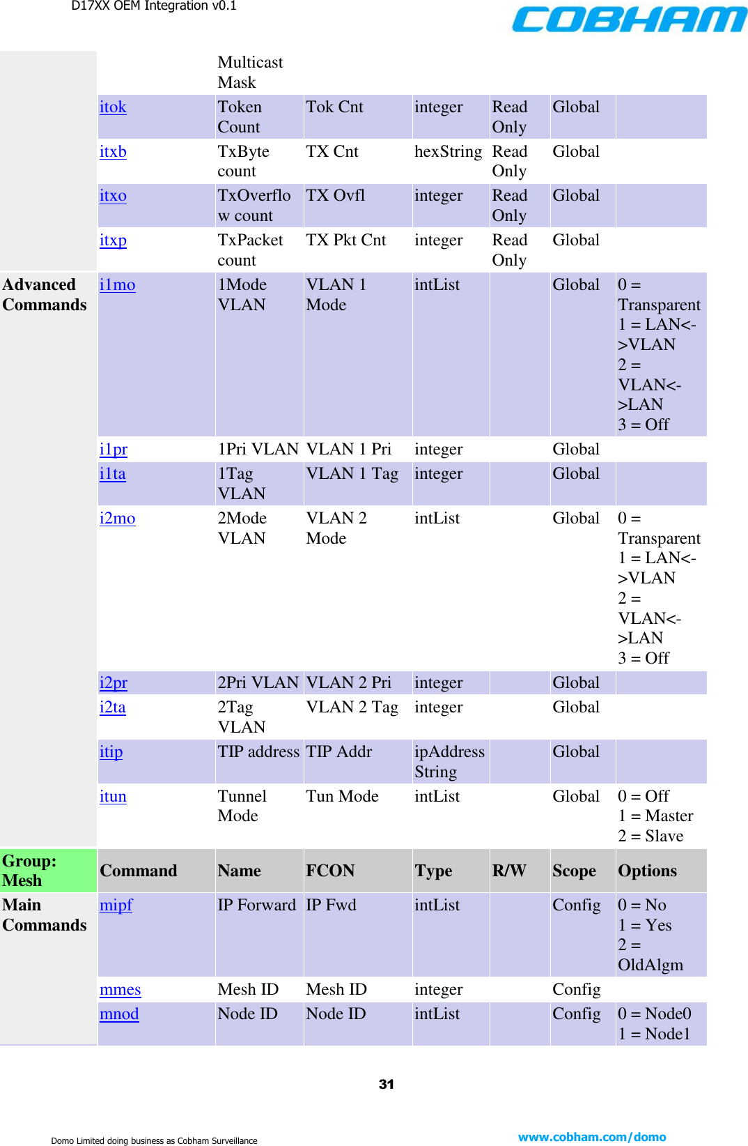
D17XX OEM Integration v0.1    31 www.cobham.com/domo  Domo Limited doing business as Cobham Surveillance Multicast Mask itok Token Count Tok Cnt integer Read Only Global  itxb TxByte count TX Cnt hexString Read Only Global  itxo TxOverflow count TX Ovfl integer Read Only Global  itxp TxPacket count TX Pkt Cnt integer Read Only Global  Advanced Commands i1mo 1Mode VLAN VLAN 1 Mode intList  Global 0 = Transparent 1 = LAN<->VLAN 2 = VLAN<->LAN 3 = Off i1pr 1Pri VLAN VLAN 1 Pri integer  Global  i1ta 1Tag VLAN VLAN 1 Tag integer  Global  i2mo 2Mode VLAN VLAN 2 Mode intList  Global 0 = Transparent 1 = LAN<->VLAN 2 = VLAN<->LAN 3 = Off i2pr 2Pri VLAN VLAN 2 Pri integer  Global  i2ta 2Tag VLAN VLAN 2 Tag integer  Global  itip TIP address TIP Addr ipAddressString  Global  itun Tunnel Mode Tun Mode intList  Global 0 = Off 1 = Master 2 = Slave Group: Mesh Command Name FCON Type R/W Scope Options Main Commands mipf IP Forward IP Fwd intList  Config 0 = No 1 = Yes 2 = OldAlgm mmes Mesh ID Mesh ID integer  Config  mnod Node ID Node ID intList  Config 0 = Node0 1 = Node1
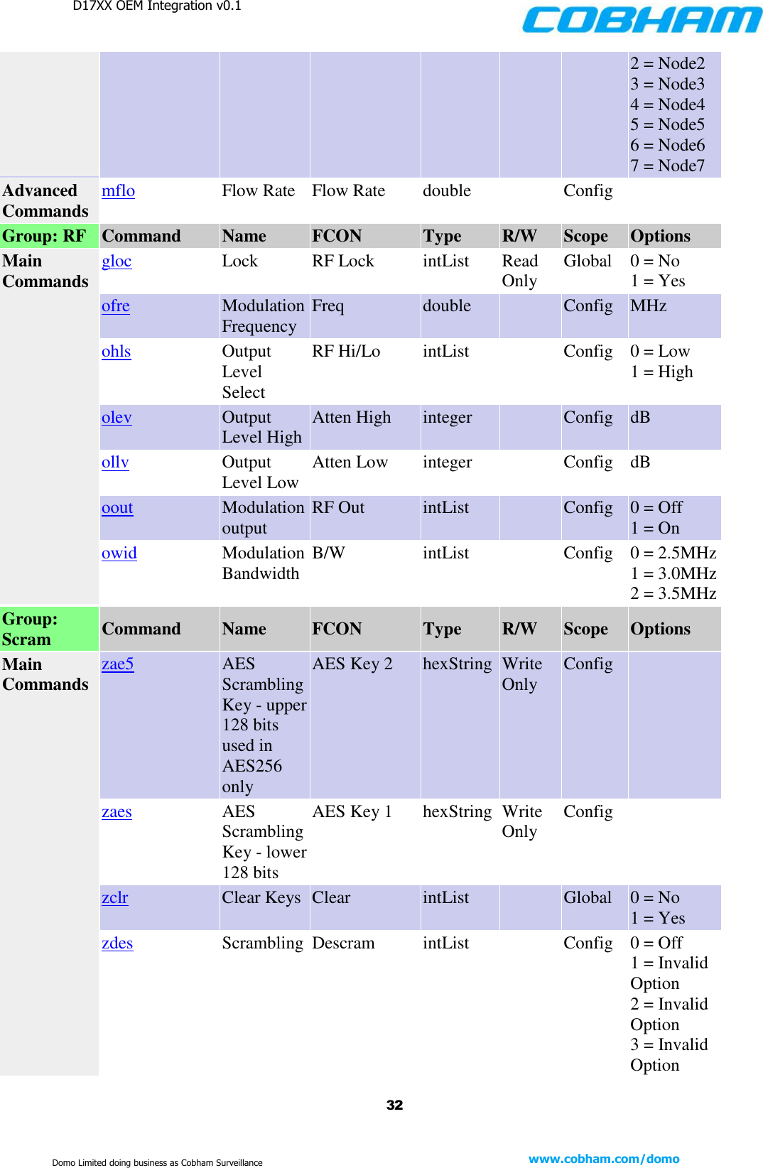
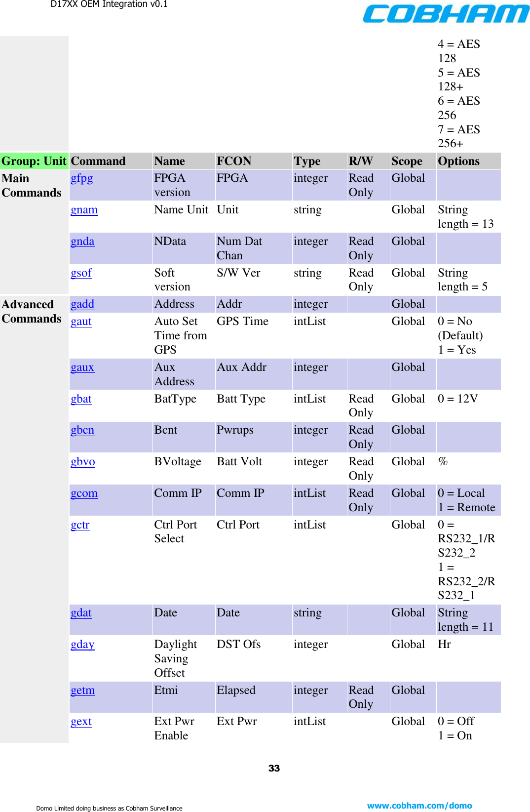
D17XX OEM Integration v0.1    32 www.cobham.com/domo  Domo Limited doing business as Cobham Surveillance 2 = Node2 3 = Node3 4 = Node4 5 = Node5 6 = Node6 7 = Node7 Advanced Commands mflo Flow Rate Flow Rate double  Config  Group: RF Command Name FCON Type R/W Scope Options Main Commands gloc Lock RF Lock intList Read Only Global 0 = No 1 = Yes ofre Modulation Frequency Freq double  Config MHz ohls Output Level Select RF Hi/Lo intList  Config 0 = Low 1 = High olev Output Level High Atten High integer  Config dB ollv Output Level Low Atten Low integer  Config dB oout Modulation output RF Out intList  Config 0 = Off 1 = On owid Modulation Bandwidth B/W intList  Config 0 = 2.5MHz 1 = 3.0MHz 2 = 3.5MHz Group: Scram Command Name FCON Type R/W Scope Options Main Commands zae5 AES Scrambling Key - upper 128 bits used in AES256 only AES Key 2 hexString Write Only Config  zaes AES Scrambling Key - lower 128 bits AES Key 1 hexString Write Only Config  zclr Clear Keys Clear intList  Global 0 = No 1 = Yes zdes Scrambling Descram intList  Config 0 = Off 1 = Invalid Option 2 = Invalid Option 3 = Invalid Option
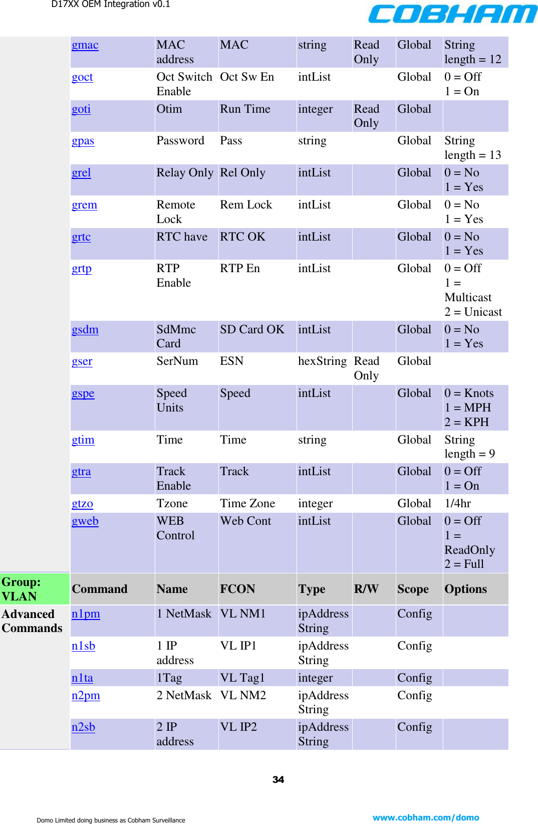
D17XX OEM Integration v0.1    33 www.cobham.com/domo  Domo Limited doing business as Cobham Surveillance 4 = AES 128 5 = AES 128+ 6 = AES 256 7 = AES 256+ Group: Unit Command Name FCON Type R/W Scope Options Main Commands gfpg FPGA version FPGA integer Read Only Global  gnam Name Unit Unit string  Global String length = 13 gnda NData Num Dat Chan integer Read Only Global  gsof Soft version S/W Ver string Read Only Global String length = 5 Advanced Commands gadd Address Addr integer  Global  gaut Auto Set Time from GPS GPS Time intList  Global 0 = No (Default) 1 = Yes gaux Aux Address Aux Addr integer  Global  gbat BatType Batt Type intList Read Only Global 0 = 12V gbcn Bcnt Pwrups integer Read Only Global  gbvo BVoltage Batt Volt integer Read Only Global % gcom Comm IP Comm IP intList Read Only Global 0 = Local 1 = Remote gctr Ctrl Port Select Ctrl Port intList  Global 0 = RS232_1/RS232_2 1 = RS232_2/RS232_1 gdat Date Date string  Global String length = 11 gday Daylight Saving Offset DST Ofs integer  Global Hr getm Etmi Elapsed integer Read Only Global  gext Ext Pwr Enable Ext Pwr intList  Global 0 = Off 1 = On
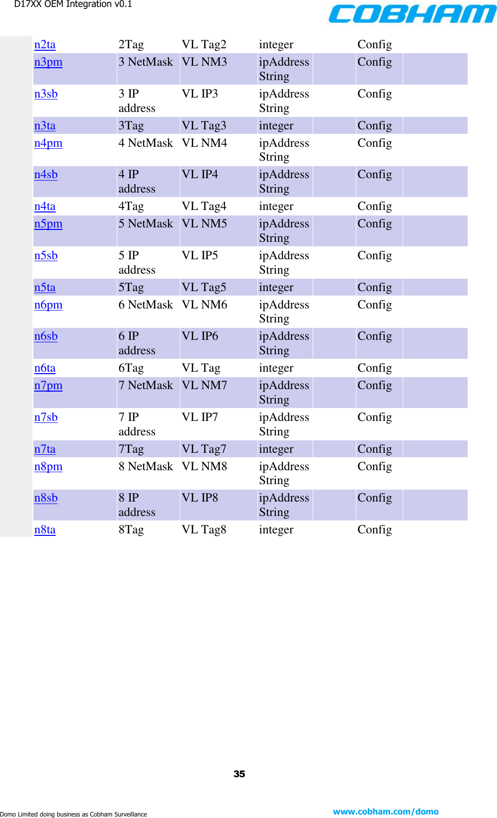
D17XX OEM Integration v0.1    34 www.cobham.com/domo  Domo Limited doing business as Cobham Surveillance gmac MAC address MAC string Read Only Global String length = 12 goct Oct Switch Enable Oct Sw En intList  Global 0 = Off 1 = On goti Otim Run Time integer Read Only Global  gpas Password Pass string  Global String length = 13 grel Relay Only Rel Only intList  Global 0 = No 1 = Yes grem Remote Lock Rem Lock intList  Global 0 = No 1 = Yes grtc RTC have RTC OK intList  Global 0 = No 1 = Yes grtp RTP Enable RTP En intList  Global 0 = Off 1 = Multicast 2 = Unicast gsdm SdMmc Card SD Card OK intList  Global 0 = No 1 = Yes gser SerNum ESN hexString Read Only Global  gspe Speed Units Speed intList  Global 0 = Knots 1 = MPH 2 = KPH gtim Time Time string  Global String length = 9 gtra Track Enable Track intList  Global 0 = Off 1 = On gtzo Tzone Time Zone integer  Global 1/4hr gweb WEB Control Web Cont intList  Global 0 = Off 1 = ReadOnly 2 = Full Group: VLAN Command Name FCON Type R/W Scope Options Advanced Commands n1pm 1 NetMask VL NM1 ipAddressString  Config  n1sb 1 IP address VL IP1 ipAddressString  Config  n1ta 1Tag VL Tag1 integer  Config  n2pm 2 NetMask VL NM2 ipAddressString  Config  n2sb 2 IP address VL IP2 ipAddressString  Config
D17XX OEM Integration v0.1    35 www.cobham.com/domo  Domo Limited doing business as Cobham Surveillance n2ta 2Tag VL Tag2 integer  Config  n3pm 3 NetMask VL NM3 ipAddressString  Config  n3sb 3 IP address VL IP3 ipAddressString  Config  n3ta 3Tag VL Tag3 integer  Config  n4pm 4 NetMask VL NM4 ipAddressString  Config  n4sb 4 IP address VL IP4 ipAddressString  Config  n4ta 4Tag VL Tag4 integer  Config  n5pm 5 NetMask VL NM5 ipAddressString  Config  n5sb 5 IP address VL IP5 ipAddressString  Config  n5ta 5Tag VL Tag5 integer  Config  n6pm 6 NetMask VL NM6 ipAddressString  Config  n6sb 6 IP address VL IP6 ipAddressString  Config  n6ta 6Tag VL Tag integer  Config  n7pm 7 NetMask VL NM7 ipAddressString  Config  n7sb 7 IP address VL IP7 ipAddressString  Config  n7ta 7Tag VL Tag7 integer  Config  n8pm 8 NetMask VL NM8 ipAddressString  Config  n8sb 8 IP address VL IP8 ipAddressString  Config  n8ta 8Tag VL Tag8 integer  Config

Navigation menu