Cobra Electronics 18WXSTII Non-Broadcast Transmitter (CB) User Manual users manual
Cobra Electronics Corporation Non-Broadcast Transmitter (CB) users manual
users manual
1
Contents
Features. . . . . . . . . . . . . . . . . . . . . . . . . . . . . . . . . . . . . . . . 1
The CB Story . . . . . . . . . . . . . . . . . . . . . . . . . . . . . . . . . . A1
Licensing/Warning/Included Accessories. . . . . . . A1
Controls and Indicators . . . . . . . . . . . . . . . . . . . . . . . A2
Our Thanks to You. . . . . . . . . . . . . . . . . . . . . . . . . . . . . A3
Customer Support . . . . . . . . . . . . . . . . . . . . . . . . . . A3
Operating Your CB Mobile Radio
Installation/Connection. . . . . . . . . . . . . . . . . . . . . . . . . . 2
Turning On. . . . . . . . . . . . . . . . . . . . . . . . . . . . . . . . . . . . . . 4
CB Antenna . . . . . . . . . . . . . . . . . . . . . . . . . . . . . . . . . . . . . 4
Microphone Connector . . . . . . . . . . . . . . . . . . . . . . . . . . 5
Squelch. . . . . . . . . . . . . . . . . . . . . . . . . . . . . . . . . . . . . . . . . 5
Setting Squelch . . . . . . . . . . . . . . . . . . . . . . . . . . . . . . . . . 6
Channel Selection . . . . . . . . . . . . . . . . . . . . . . . . . . . . . . . 8
Channel 9/19. . . . . . . . . . . . . . . . . . . . . . . . . . . . . . . . . . . . 8
CB/Weather. . . . . . . . . . . . . . . . . . . . . . . . . . . . . . . . . . . . . 8
Dual Watch. . . . . . . . . . . . . . . . . . . . . . . . . . . . . . . . . . . . . . 9
Scan. . . . . . . . . . . . . . . . . . . . . . . . . . . . . . . . . . . . . . . . . . . . 9
Soundtracker System . . . . . . . . . . . . . . . . . . . . . . . . . . . 10
Activating Soundtracker System. . . . . . . . . . . . . . . . . 11
S/RF Power Meter . . . . . . . . . . . . . . . . . . . . . . . . . . . . . . 12
RX/TX Indicator LED . . . . . . . . . . . . . . . . . . . . . . . . . . . . 12
Antenna Connector. . . . . . . . . . . . . . . . . . . . . . . . . . . . . 13
External Speaker . . . . . . . . . . . . . . . . . . . . . . . . . . . . . . . 13
Power . . . . . . . . . . . . . . . . . . . . . . . . . . . . . . . . . . . . . . . . . 13
Ignition Noise Interference. . . . . . . . . . . . . . . . . . . . . . 14
Temporary Mobile Operation. . . . . . . . . . . . . . . . . . . . 14
Operation to Receive/Transmit . . . . . . . . . . . . . . . . . . 15
Maintenance. . . . . . . . . . . . . . . . . . . . . . . . . . . . . . . . . . . 16
Frequency Ranges. . . . . . . . . . . . . . . . . . . . . . . . . . . . . . 18
Specifications . . . . . . . . . . . . . . . . . . . . . . . . . . . . . . . . . 19
Accessories . . . . . . . . . . . . . . . . . . . . . . . . . . . . . . . . . . . . 20
Warranty. . . . . . . . . . . . . . . . . . . . . . . . . . . . . . . . . . . . . . 21
IfYou Think You Need Service . . . . . . . . . Back Cover
Features of This Product
• 40 CB Radio Channels
• 10 Weather Channels
• SoundtrackerTMSystem
• Instant Channel 19 and 9
• 40 Channel Scan
• Dual Watch
• Front Firing Speaker
• Channel Saver Circuitry
• Dynamic Microphone
• 9 Foot Mic Cord
• Front Panel Microphone
Connector
How to Use Your
Cobra 18WXST II
18 WX ST.NEW LAYOUT(4279)2a 8/9/00 4:25 PM Page 1
3
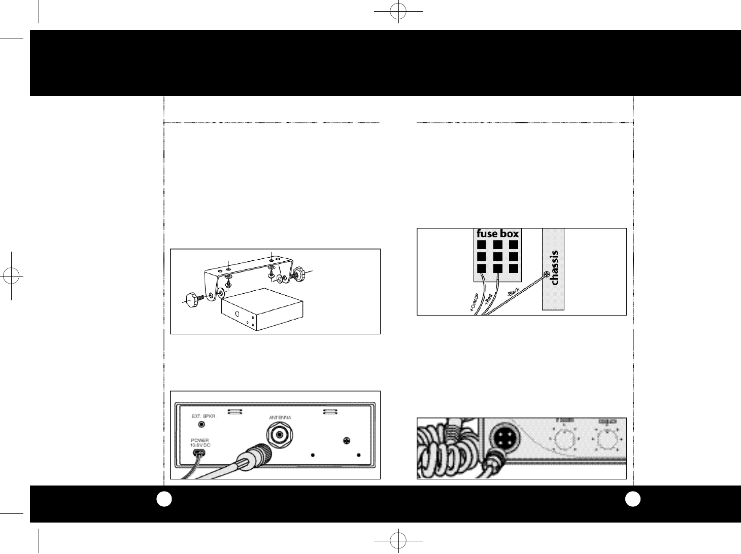
ᕤCo n n e c t the red lead of DC power co r d to an
a c ce s s o r y 12 volt fuse.
ᕥCo n n e ct the orange lead to a co n s t a n t 12v fuse
( i e :c i g a re t te lighter or dire ct to bat te ry )
ᕦCo n n e ct the black lead to the negat i ve side of
the auto m o b i l e.This is usually the chassis.Any
co nve n i e nt location with good elect ri cal co nt a ct
( re m ove paint) may be used.
ᕧMo u n t the microphone bra c k et on ri g ht side of
the tra n s ce i ver or near it using two scre ws sup-
p l i e d .When mounting in an auto m o b i l e,p l a c e
the bra c ket under the dash so the micro p h o n e
is readily acce s s i b l e.
ᕨAttach the 4-pin microphone cable to recepta-
cle on front of unit and install unit in bracket-
securely.
Mounting and
Connections
Note
Before installing the CB radio,
visually check the vehicle bat-
tery connections to determine
which battery terminal, posi-
tive or negative (positive is the
larger of the two) is grounded
to the engine block
(or chassis).
O p e r a t i o n
2
Mo u n ting and Co n n e ct i o n s
Se l e ct a location for the tra n s ce i ver and micro-
phone bra c ket that is co n ve n i e nt for ope rat i o n .
In auto m o b i l e s,the tra n s ce i v er is usually mounte d
to the undern e ath of the dash panel,with the
m i c r ophone bra c ket beside it.
ᕡHold the radio with mounting bra c k et in the
ex a ct location desire d.Re m o ve the mount i n g
b ra c k et and use it as a te m p l a te to mark the
l ocation for the mounting scre w s.
ᕢDrill nece s s a ry holes and secure mount i n g
b ra c ket in locat i o n .
ᕣCo n n e ct the antenna cable plug to the re ce p t a-
cle marked “A N T”on the back of the unit.
Mounting and
Connections
Note
The transceiver is held in the
universal mounting bracket by
two thumb screws,permitting
adjustment at the most conve-
nient angle.
A universal mounting bracket
is supplied along with self tap-
ping screws and star washers.
To mount the transceiver:
O p e r a t i o nInstallation Installation
CB Transceiver
18 WX ST.NEW LAYOUT(4279)2a 8/9/00 4:25 PM Page 2
5
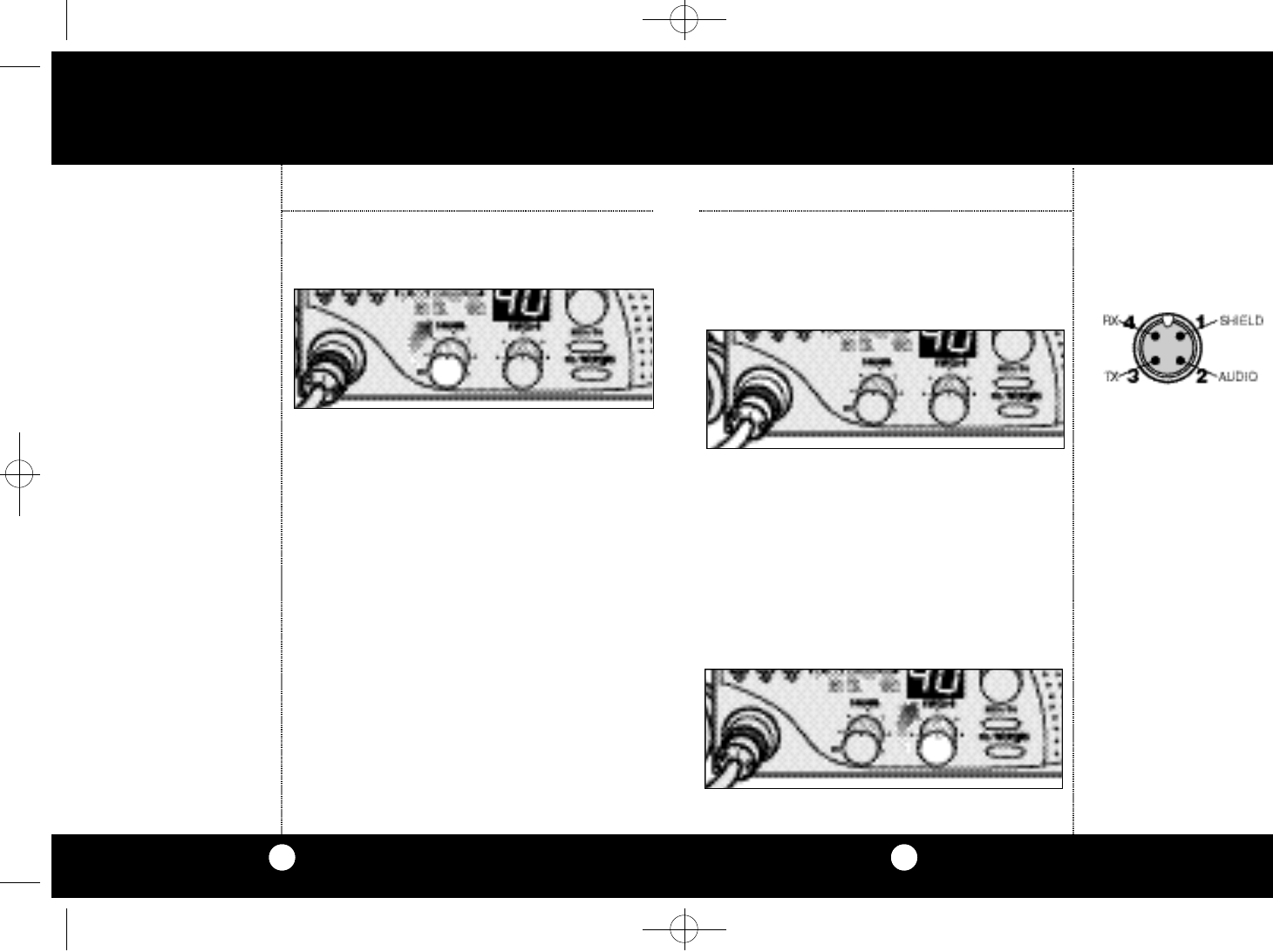
Mi c r ophone Co n n e ctor
Al l ows for co nve n i e nt re m oval of the micro p h o n e
plug when sto rage is re q u i re d.The micro p h o n e
MUST be co n n e cted to the unit at all times when in
u s e,for pro per ope r at i o n .
Sq u e l c h
This co nt rol is used to cut off or eliminate re ce i ve r
b a c kg r ound noise in the absence of an inco m i n g
s i g n a l . Adjust until the re ce i ver noise disappe a r s.
This will re q u i r e the incoming signal to be slight l y
s t r onger than ave rage re ce i ver noise.Fu rther cloc k -
wise ro t ation will increase the threshold leve l
which a signal must ove rcome in order to be heard.
Only strong signals will be heard at a maximum
c l oc kwise setting.
Microphone
Connector
O p e r a t i o n
Squelch
4
Tu rning on
Tu rn volume co nt r ol cloc k wise to turn power on
and set the desired listening vo l u m e.
CB Ante n n a
Only a pro pe rly matched antenna sys t em will
a l l o w maximum power output.
In mobile installations (ca r s ,t ru c k s,bo at s,e tc. ) ,
an antenna sys tem that is non-dire ctional should
be used.
When installed in a bo at,the tra n s ce i v er will not
o pe r ate at maximum efficiency without a gro u n d
p l a te unless the vessel has a steel hull.Be fo re
installing the tra n s ce i ver in a bo a t,consult yo u r
dealer for info rm ation re g a r ding an adequate
g r ounding sys te m .
Turning on
Your Radio
Operation
CB Antenna
No te
Co b ra loaded-ty pe ante n n a
m odels HGA 1000,HGA 1500,
and HGA 2000 are highly re c -
ommended for most installa-
t i o n s. Consult your Co b ra deal-
er for further details (or see
o rder form at the back of
this boo k ) .
3 - Way Combination An te n n a s
a re available which allow ope r-
ation of all three bands (AM-FM
& CB), using a single ante n n a .
Howeve r,use of this ty pe of
a n tenna usually results in less
than normal transmit and
re ce i ve range when co m p a re d
to a standard - ty pe "Si n g l e
Band" antenna designed for
CB only.
18 WX ST.NEW LAYOUT(4279)2a 8/9/00 4:25 PM Page 4
7
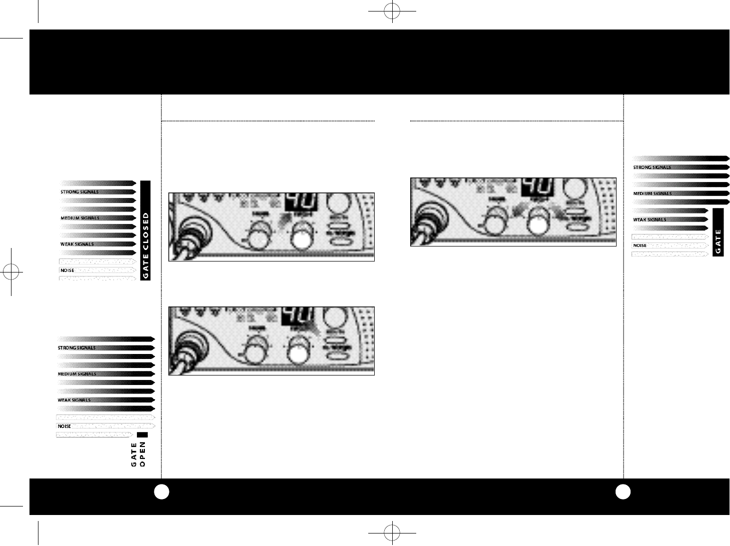
3 . To achieve the De s i red Squelch Setting (DSS),
t u r n the Squelch co nt rol co u n te rc l oc kw i s eu nt i l
you hear noise. Now turn the co nt rol c l oc kw i s e
just until the noise sto p s. This is the DSS setting.
O p e r a t i o n
Gate set to Desired
Squelch Setting (DSS)
6
O p e r a t i o n
Gate open
Gate closed
Setting
Squelch
Setting Squelch
Squelch is the “control gate”for incoming signals.
1 . Fullclockwise rotation closes the gate
allowing only very strong signals to enter.
2 . Fullcounterclockwise rotation opens the “gate”
allowing all signals in.
18 WX ST.NEW LAYOUT(4279)2a 8/9/00 4:25 PM Page 6
9
Dual Watc h
This fe at u r es allows the user to scan be t ween two
s e l e cted channels.
1 . Se l e ct first channel,CB mod e.
2 . Press and hold DW until LED begins flashing and
beeps once.
3 . Se l e ct second channel.Press DW until LED light s
s te a d y and radio beeps tw i c e. Two channels are
n o w sto r ed in DW memory.
S ca n
Press and release SCAN button to act i vate CB sca n
m od e .If the radio is squelched,radio begins to sca n .
When scan is inte rru p t ed by a signal,s can stops and
holds until loss of signal.Press PTT on mic to sto p
s can funct i o n . Press Scan to re s t a rt CB sca n .
Channel
Selection
O p e r a t i o n
8
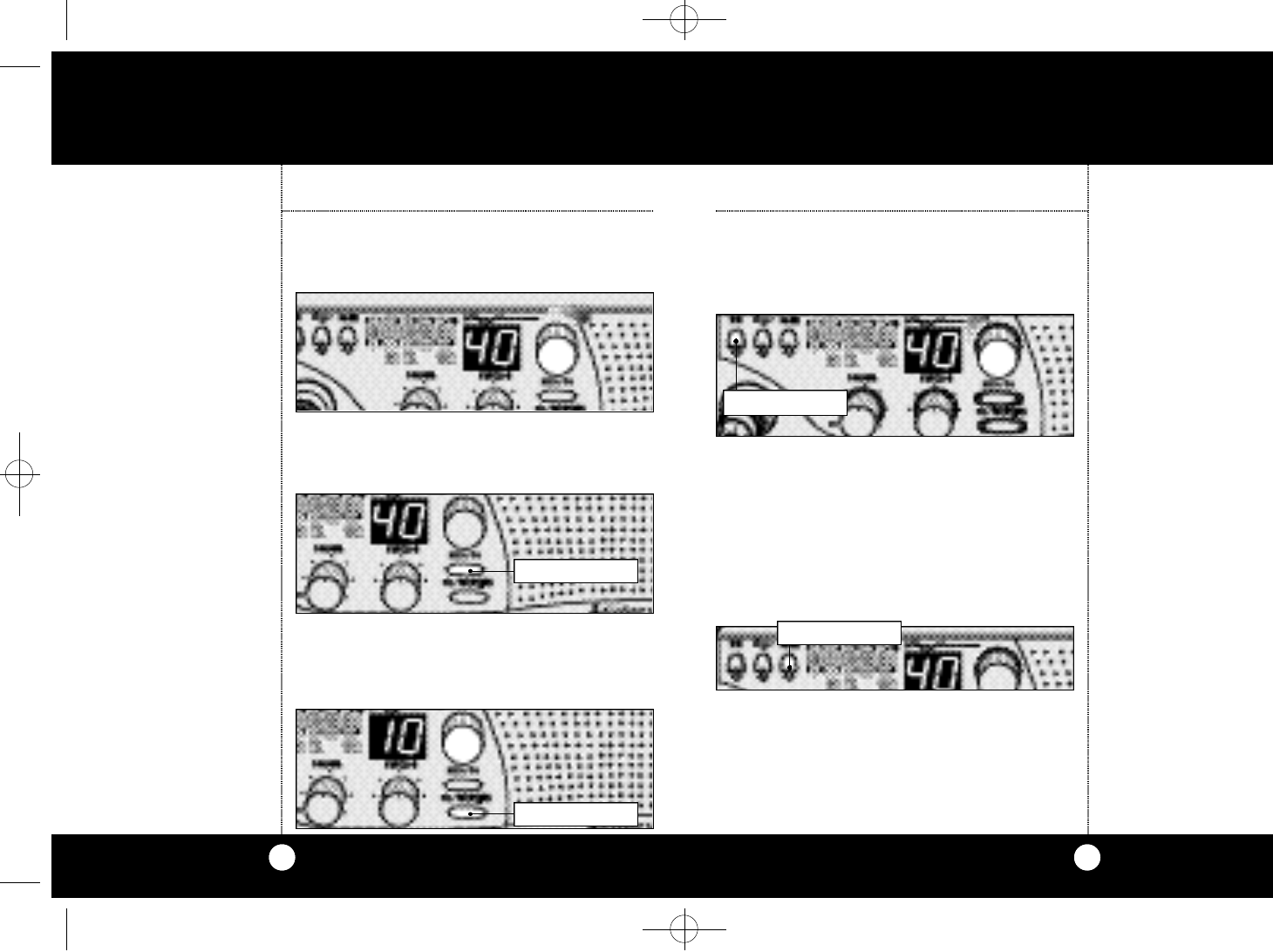
Set CB or W X Mod e
Set on CB mod e . Ro t ate channel knob cloc kw i s e
u n til desired channel is displaye d .
Channel 9/Channel 19
Press CH 9/19 to obtain instant access to emerg e n cy
channel 9.Press again for info rm ation CH 19.
C B / We at h e r
CB mode is for normal CB ope rat i o n .Pre s s
C B / We a ther again and select act i v e We a ther channel
in your are a .
O p e r a t i o n
PRESS AND RELEASE
Channel 9/
Channel 19
CB Weather
Dual Watch
Note
The radio needs to be
squelched before DW can
monitor both channels.
Scan
Note
On some channels squelch
setting might have to be re-set.
PRESS AND HOLD
PRESS AND RELEASE
PRESS AND RELEASE
18 WX ST.NEW LAYOUT(4279)2a 8/9/00 4:25 PM Page 8
11
Activating Soundtracker
1 . Press the SoundTracker button on the upper
left side of front panel.A red indicator will
illuminate when the SoundTracker system is
engaged.
Activating
Soundtracker
O p e r a t i o n
10
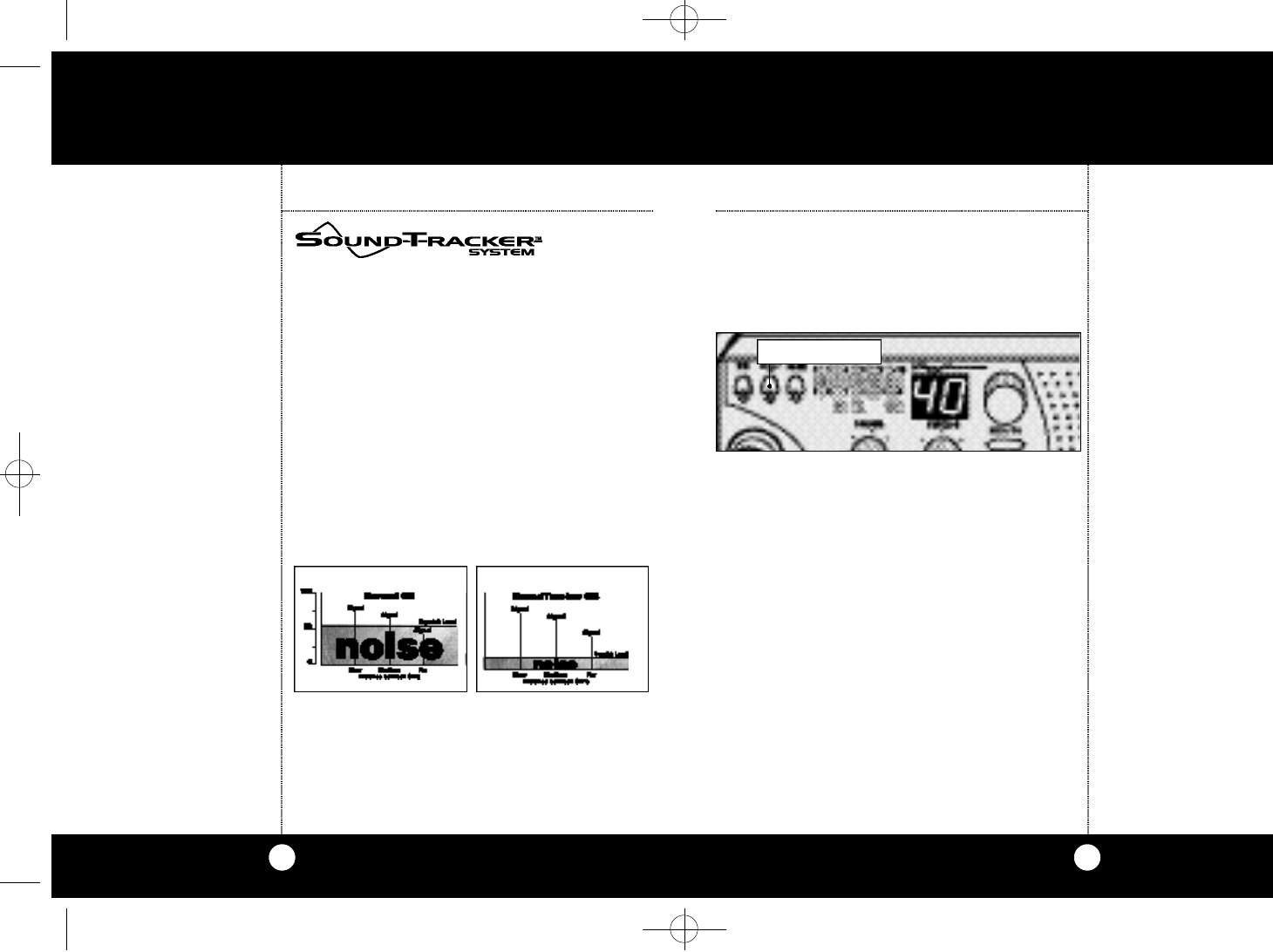
The SoundTracker System reduces noise while
leaving the signal intact in the reception mode.
In the transmission mode,it strengthens the sig-
nal,providing you with a significant reduction in
noise on reception and transmission.
How SoundTracker works
On Reception–
“Cuts Noise Coming In”
With a normal CB,distant signals fall below the
squelch level and are unintelligible.With a
SoundTracker CB,the noise level is cut by up to
90%,which increases the signal-to-noise ratio
and dramatically improves signal clarity.This also
allows you to significantly reduce the squelch
level,which greatly expands your listening range.
On Transmission–
“Strengthens Signals Going Out”
A SoundTracker CB strengthens the transmit sig-
nal by more effectively using the available RF
power output of the CB.The result is improved
transmission signal clarity and an expanded
transmission range.
Soundtracker
System
O p e r a t i o n
PUSH AND RELEASE
USPat.No.6,038,429
18 WX ST.NEW LAYOUT(4279)2a 8/9/00 4:25 PM Page 10
13
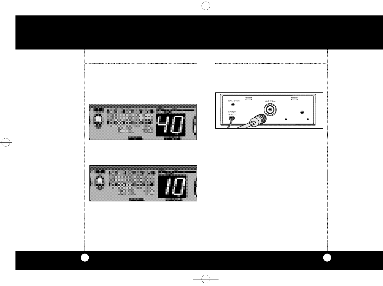
Rear Pa n e l
Antenna Co n n e c to r.This female connector per-
mits connection of the transmission line cable
male connector to the transceiver.
Exte rnal Spe a ke r.The External Speaker Jack is
used for an external speaker.The external speak-
er should have 8-ohm impedance and be rated
to handle at least 4.0 watts.When the external
speaker is plugged in,the internal speaker is
automatically disconnected.
Powe r :This cable is permanently attached to the
radio.If you wish to remove the radio after instal-
lation,disconnect at fuse holder and ground
connector.
Antenna
Connector
O p e r a t i o n
12
S/RF Power Me te r
Sh o ws re l at i ve tra n s m i t ter RF output power and
input signal strength when re ce i v i n g.The LED
( L i g ht Emitting Di ode) segments glow green to
a m ber to re d...this indicates re ce i v e or tra n s m i t
a ct i v i ty.
RX / TX Indicator LED
RX indicator will light when in the re ce i ve mod e .
TX indicator lights when in transmit mod e.
When we ather channel is selecte d,WX indicator is
i l l u m i n a te d, and the channel is displaye d.
S/RF
PowerMeter
O p e r a t i o n
RX/TX
Indicator LED
External
Speaker
Power
Note
Co b ra external spe a kers are
ra ted 15 wa t t s
18 WX ST.NEW LAYOUT(4279)2a 8/9/00 4:25 PM Page 12
15
Operating Procedure to Receive
1 . Be sure that power cord, antenna and microphone are connected to the
proper connectors before proceeding further.The weather switch should
be in the "CB" position.
2 . Turn the radio ON by rotating the VOLUME CONTROL clockwise.
3 . Rotate SQUELCH CONTROL counterclockwise until incoming signal is
heard.
4 . Select the desired channel.
5 . Set VOLUME CONTROL to a comfortable listening level.
6 . Engage the SoundTracker system by depressing the button labeled ST.
Listen to the background noise from the speaker.Turn the SQUELCH CON-
TROL slowly clockwise until the noise JUST disappears (no signal should be
present).Leave the control at this setting.The squelch is now properly
adjusted.The receiver will remain quiet until a signal is actually received.Do
not advance the control too far,or some of the weaker signals will not be
heard.The revolutionary SoundTracker system allows you to reduce
unwanted background noise (static) and increase the signal for better
reception.
Operating Procedure to Transmit
1 . Select the desired channel.
2 . The receiver and transmitter are controlled by the press-to-talk switch on
the microphone. Press the switch and the transmitter is activated;release
switch to receive.When transmitting (on a clear channel),hold the micro-
phone two inches from the mouth and speak clearly in a normal voice.
Be sure the antenna is properly connected to the radio before transmit-
ting.Prolonged transmitting without an antenna,or a poorly matched
antenna,could cause damage to the transmitter.
O p e r a t i o n
14
Ignition Noise Inte rfe re n c e
Use of a mobile re ce i ver at low signal levels is nor-
mally limited by the pre s e n ce of elect ri cal noise.
Under most ope rating co n d i t i o n s,when signal
l e vel is adequate,the backg r ound noise does not
p re s e nt a serious pro b l e m .Al s o,when ext re m e l y
l o w level signals are being re ce i ve d,the tra n s ce i ve r
m a y be ope r ated with vehicle engine turned off.
The unit re q u i res ve ry little curre nt and there fo re
will not significa n tly discharge the vehicle bat te ry.
Even though this radio has an auto m a tic noise lim-
i te r,in some installations ignition inte rfe re n c e may
be high enough to make good co m m u n i cat i o n s
i m po s s i b l e .Consult your CO B RA dealer or a 2-way
radio technician for help in locating and co r re ct i n g
the source of seve re noise.
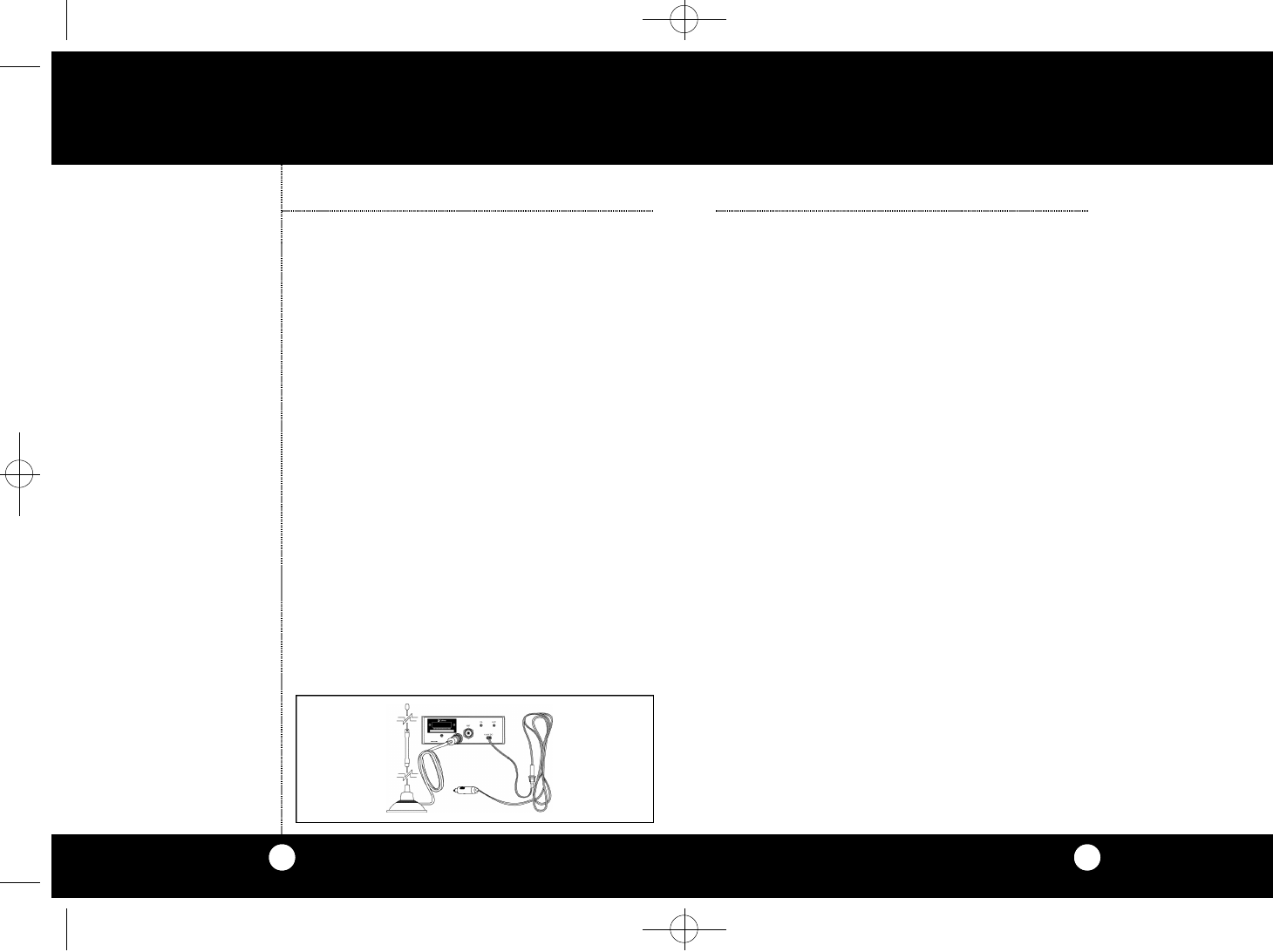
Te m po ra ry Mobile Ope r at i o n
For te m po ra ry mobile ope rat i o n ,you may wa n t to
p u rchase an additional cigare t te lighter adapte r
f r om your CO B RA dealer.This adapter and a mag-
netic mount antenna allow you to quickly "install"
your tra n s ce i ver for te m po ra ry use.
O p e r a t i o n
Ignition Noise
Interference
Temporary
Mobile
Operation
Note
Red and Orange wires are co n-
n e cted to po s i t i ve side of soc ke t
ce n ter tip.Black wire is co n n e ct-
ed to negative side co n t a ct s.
Note
Radio resets to CH 9 when co n -
n e cted to cigare t te lighter plug.
Note
When using the unit with cig-
a re t te adapte r, turn off when
not in use to avoid draining
the batte ry.
18 WX ST.NEW LAYOUT(4279)2a 8/9/00 4:25 PM Page 14

16
Maintenance/
Adjustment
M a i n t e n a n c e
Maintenance and Adjustment
Your COBRA CB transceiver is specifically
designed for the environment encountered in
mobile installations.The use of all solid state cir-
cuitry and its light weight result in high reliabili-
ty.Should a failure occur,however,review the fol-
lowing,then if necessary, replace parts only with
identical parts. Do not substitute.
1 . Check connections to the source of power and
make sure it is the 13.8 VDC required to oper-
ate your radio.
2 . Check the fuses in the DC power cord.The
main power lead (red & orange wire) has a 2
amp 3AG type fuse in its holder.Use only the
above specified type and size fuse for maxi-
mum protection. Failure to do so,will void the
warranty.
3 . Ma ke ce rtain the microphone is pro pe rl y
plugged in.
4 . Make certain the antenna is properly assem-
bled and connected.
If you are unable to correct the problem, refer to
the SERVICE INSTRUCTIONS at the end of this
manual for the correct procedure for warranty
and post-warranty service from COBRA.
Permitted:"A tornado sighted six miles of town."
Not Permitted : "This is observation post number 10.
No tornado sighted."
Wa rn i n g
17
Channel 9
Emergency
Messages
Replacement Warning
Replacement or substitution of certain parts with
replacements other than those recommended by
Cobra may be a violation of the technical regula-
tions of Part 95 of the FCC rules, or of Type
Acceptance requirements of Part 2 of said rules.
When making adjustment s,be sure to re - re a d
a p p l i cable po rtions of this instru ction manual to
m a ke ce rtain you are fo l l owing co rre ct proce d u r e
and that the radio was pro pe rly installed,e tc.
A Few Rules That Should Be Obeyed
1. You are not allowed to carry on a conversation with
another station for more than five minutes at a time with-
out taking a one-minute break to give others a chance to
use the channel.
2. You are not allowed to blast others off the air by overpow-
ering them with illegally amplified transmitter power or
illegally high antennas.
3. You can't use CB to promote illegal activities.
4. You are not allowed to use profanity.
5. You may not play music in your CB.
6. You may not use your CB to sell merchandise or profes-
sional service.
Use Channel 9 For Emergency Messages Only
The FCC gives the following examples of permit-
ted and prohibited types of communications for
use on Channel 9.These are guidelines and are
not intended to be all-inclusive.
A Few Rules
You Should
Know
18 WX ST.NEW LAYOUT(4279)2a 8/9/00 4:25 PM Page 16
19
A c c e s s o r i e s
18
Specifications
S p e c i f i c a t i o n s
GENERAL
CHANNELS. . . . . . . . . . . . . . . . . . . . . . . CB - 40 CH
WEATHER – 10CH
FREQUENCY RANGE. . . . . . . . . . . . . . . CB - 26.965 TO 27.405 MHZ
WEATHER – 161.650 TO 163.275
FREQUENCY TOLERANCE. . . . . . . . . . 0.005 %
FREQUENCY CONTROL . . . . . . . . . . . . PLL (PHASE LOCK LOOP) SYNTHESIZER
OPERATING TEMPERATURE
RANGE. . . . . . . . . . . . . . . . . . . . . . . . . . . -30° C TO + 65° C
MICROPHONE . . . . . . . . . . . . . . . . . . . . PLUG-IN DYNAMIC
INPUT VOLTAGE . . . . . . . . . . . . . . . . . . 13.8VDC nom.(negative ground)
CURRENT DRAIN TRANSMIT:AM FULL MOD.,1.4A (MAXIMUM)
RECEIVE:SQUELCHED,0.9 A;
FULL AUDIO OUTPUT, 1.2A (NOMINAL)
SIZE . . . . . . . . . . . . . . . . . . . . . . . . . . . . .6-7/8”D X 6-3/4”W X 1-7/8”H
WEIGHT . . . . . . . . . . . . . . . . . . . . . . . . . .4.25 LBS.
ANTENNA CONNECTOR . . . . . . . . . . . .UHF;SO-239
METER . . . . . . . . . . . . . . . . . . . . . . . . . . .LED;INDICATES RELATIVE POWER
OUTPUT AND RECEIVED SIGNAL STRENGTH
TRANSMITTER
POWER OUTPUT . . . . . . . . . . . . . . . . . .4 WATTS
MODULATION . . . . . . . . . . . . . . . . . . . .AM (AMPLITUDE MODULATION)
FREQUENCY RESPONSE . . . . . . . . . . . .300 TO 3000 HZ
OUTPUT IMPEDANCE . . . . . . . . . . . . . .50 OHMS,UNBALANCED
RECEIVER
SENSITIVITY . . . . . . . . . . . . . . . . . . . . . . .LESS THAN 1 µV FOR 10dB (S+N)
SELECTIVITY . . . . . . . . . . . . . . . . . . . . . .6 dB @ 7 KHZ,60 DB @ 10KHZ
IMAGE REJECTION . . . . . . . . . . . . . . . . .60 dB,TYPICAL
ADJACENT-CHANNEL REJECTION . . .50 dB,TYPICAL
ATOMATIC NOISE LIMITER . . . . . . . . . .BUILT-IN
WEATHER
SENSITIVITY . . . . . . . . . . . . . . . . . . . . . . .LESS THAN 1 µV FOR 12 dB SINAD
IF-FREQUENCY . . . . . . . . . . . . . . . . . . . .DUAL CONVERSION
AUDIO OUTPUT . . . . . . . . . . . . . . . . . . .MAXIMUM 1 W AT 10% DISTORTION
FREQUENCY RESPONSE . . . . . . . . . . . .300 – 3000 HZ AT -6 dB
F r equency Ranges
The CO B RA 18 WX ST II tra n s ce i v er re p re s e nts one of
the most adva n ced AM two - w ay radios used as a Cl a s s
D station in the Ci t i zens Radio Se rv i c e.This unit fe at u re s
a dva n ced Phase Lock Loop (PLL) circ u i t ry prov i d i n g
co m p l e te cove rage of all 40 CB channels and all 10
we a ther channels as shown be l ow.
1 26.965 21 27.215
2 26.975 22 27.225
3 26.985 23 27.255
4 27.005 24 27.235
5 27.015 25 27.245
6 27.025 26 27.265
7 27.035 27 27.275
8 27.055 28 27.285
9 27.065 29 27.295
10 27.075 30 27.305
11 27.085 31 27.315
12 27.105 32 27.325
13 27.115 33 27.335
14 27.125 34 27.345
15 27.135 35 27.355
16 27.155 36 27.365
17 27.165 37 27.375
18 27.175 38 27.385
19 27.185 39 27.395
20 27.205 40 27.405
Channel Channel
CB Freq. CB Freq.
Channel In MHz Channel In MHz
Weather
Weather Freq.
Channel In MHz
1 162.550
2 162.400
3 162.475
4 162.425
5 162.450
6 162.500
7 162.525
8 161.650
9 161.775
10 163.275
18 WX ST.NEW LAYOUT(4279)2a 8/9/00 4:25 PM Page 18
20
A c c e s s o r i e s
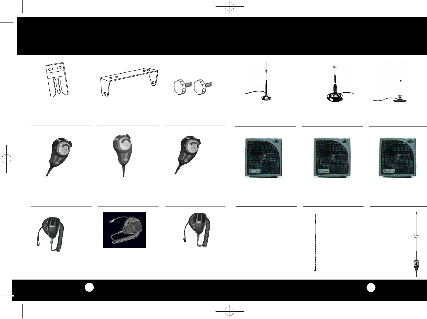
Replacement Mounting
Bracket
251-199-9-001 $4.50
Replacement Thumb Screws
634-081-9-001 $0.60
Replacement Microphone
Bracket
741-080-9-001 $0.45 38” Base Loaded Magnet
Mount Antenna
HG A1500 $46.95
54” Base Loaded Magnet
Mount Antenna
HG A2000
$99.95
21” Base Loaded Magnet
Mount Antenna
HG A1000 $28.95
Dynamic External Speaker
HG S100 $21.95 Noise Canceling External
Speaker
HG S300 $28.95
Dynamic Noise Canceling
With Talk Back External
Speaker
HG S500 $32.95
Fiberglass Whip
Replacement Antenna
3 Foot HG A300 $28.95
Black,Red,White,Gold
4 Foot HG A400 $29.95
Black,Red,White
4 1/2 Foot HG A450 $30.95
Black,Red,White,Gold
A c c e s s o r i e s
62” Center-Load
Replacement Antenna
HG A6000 $89.95
Black/Clear,Black,Red,White,Gold
21
4-Pin Power Microphone
HG M75 $25.95
4-Pin Noise Canceling
Microphone
HG M77 $30.95
4-Pin Replacement Dynamic
Microphone
HG M73 $19.95
4 Pin Premium Noise-
Cancelling Microphone
HG M84 $74.95
4 Pin Premium Noise-
Cancelling Microphone
Wood Grain
HG M84W $74.95
5 Pin Premium Noise-
Cancelling Microphone
HG M85 $74.95
18 WX ST.NEW LAYOUT(4279)2a 8/9/00 4:26 PM Page 20
23
Limited Two Year Wa r
r a n t y
Limited Warranty
COBRA ELECTRONICS CORPORATION warrants that its
COBRA CB Transceiver,and the component parts thereof,will
be free of defects in material and workmanship for a period
of two (2) years from the date of consumer purchase.This
warranty may be enforced by the first consumer purchaser,
provided that the product is utilized within the U.S.A.
COBRA will,without charge, repair or replace,at its option, a
defective CB Transceiver upon delivery to the COBRA factory
Service Department,accompanied by proof of the date of
first consumer purchase,such a duplicated sales receipt.
You must pay initial shipping charges required to ship the
product for warranty service,but the return charges will be
at COBRA’S expense,if the product is repaired or replaced
under warranty.
Exclusions:This limited warranty does not apply; 1) to any
product damaged by accident;2) in the event of misuse or
abuse of the product or as a result of unauthorized alter-
ations or repairs;3) if the serial number has been altered,
defaced or removed;4) if the owner of the product resides
outside the U.S.A.
All implied wa r ra nt i e s ,including wa rra nties of mer-
c h a nt a b i l i ty and fitness for a particular purpose are limite d
in duration to the length of this wa rra nty.
CO B RA shall not be liable for any incident a l ,co n s e q u e nt i a l
or other damages;i n c l u d i n g ,without limitat i o n ,d a m a g e s
resulting from loss of use or cost of installat i o n .
Some states do not allow limitations on how long an
implied wa rra nty lasts and/or do not allow the exclusion or
l i m i t ation of incidental or co n s e q u e ntial damages,so the
a bove limitations may not apply to yo u.
Cobra Electronics
Corporation
6500 West Cortland Street
Chicago, Illinois 60707
Tax Table
Illinois residents add 7%
Cook Co.residents add .75% (7.75% total)
Chicago residents add 1% (8.75% total)
Indiana residents add 5%
For credit card orders fill out order form
and fax to: 1.773.622.2269
or call 1.773.889.3087
(Press 1 from the main menu)
8:00 am - 8:00 pm,M-F,CST.
Ma ke check or money order (no stamps)
payable to:
Cobra Accessories Dept.
6500 West Co rtland St .Ch i ca g o,IL 60707
Prices subject to change without notice.
Please print clearly
Name_ _ _ _ _ _ _ _ _ _ _ _ _ _ _ _ _ _ _ _ _ _ _ _ _ _ _ _ _ _ _ _ _ _ _ _ _ _ _ _ _ _ _ _ _ _ _ _ _ _ _
Address (No P.O.Box)_ _ _ _ _ _ _ _ _ _ _ _ _ _ _ _ _ _ _ _ _ _ _ _ _ _ _ _ _ _ _ _ _ _ _ _ _
City_ _ _ _ _ _ _ _ _ _ _ _ _ _ _ _ _ _ _ _ _ _ _ _ _ _ _ _ _ _ _ _ _ _ _ _State_ _ _ _ _ _ _ _ _ _ _ _
Zip_ _ _ _ _ _ _ _ _ _ _ _ _Telephone (_ _ _ _ )_ _ _ _ _ _ _ _ _ _ _ _ _ _ _ _ _ _ _ _ _ _ _ _ _ _
Credit Card No._ _ _ _ _ _ _ _ _ _ _ _ _ _ _ _ _ _ _ _ _ _ _ _ _ Exp. Date_ _ _ _ _ _ _ _ _
Customer Signature_ _ _ _ _ _ _ _ _ _ _ _ _ _ _ _ _ _ _ _ _ _ _ _ _ _ _ _ _ _ _ _ _ _
Circle One: Visa MasterCard Discover
Subtotal
(Tax if applicable)
Shipping/handling
Total
Michigan residents add 4 %
Ohio residents add 6%
Wisconsin residents add 5%
Shipping & Handling
Amount of Shipping/
Order Handling
$25.00 and under $4.75 minimum
$25.01-$40.00 $6.95
$40.01-$80.00 $9.00
$80.01-$120.00 $10.00
$120.01-$160.00 $11.50
$160.01 and up $14.25
For AK,HI and PR please add
an additional $15.00 for UPS
shipments.
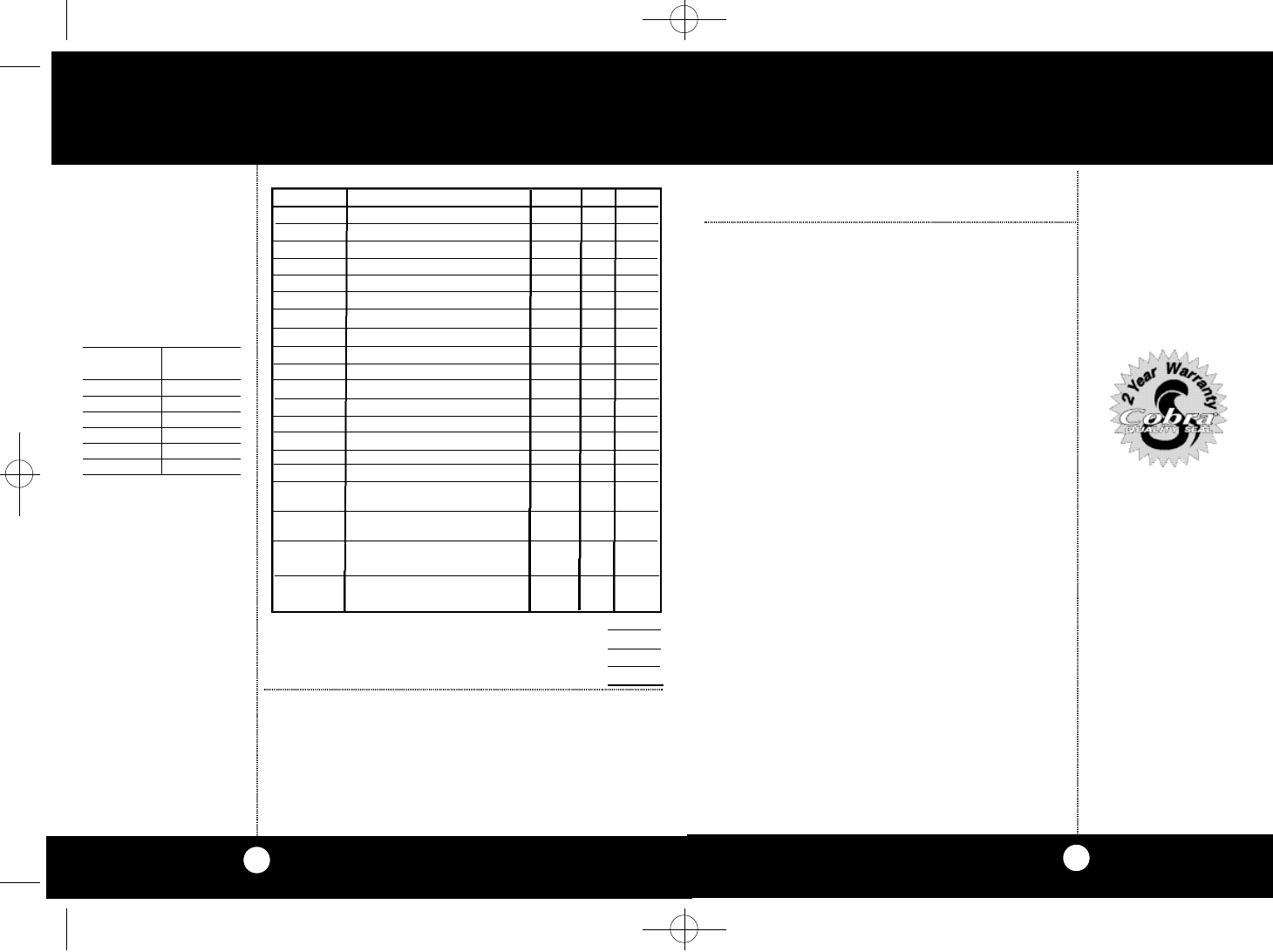
A c c e s s o ry Order Form
22
2 5 1 - 1 9 9 - 9 - 0 0 1 Re p l a ce m e nt Mo u nting Bra c ke t $ 4 . 5 0
634-081-9-001 ReplacementThumb Screws $0.60
741-080-9-001 Replacement Microphone Bracket $0.45
HG A1000 2 1 ”Base Loaded Magnetic Mo u nt Ante n n a $28.95
HG A1500 3 8 ”Base Loaded Magnetic Mo u nt Ante n n a $46.95
HG A2000 5 4 ”Base Loaded Magnetic Mo u n t Ante n n a $99.95
HG M84 4 Pin Premium No i s e - Ca n c elling Mi c ro p h o n e $74.95
HG M84W 4 Pin Premium No i s e - Ca n c elling Mic Wood gr $74.95
HG M85 5 Pin Premium No i s e - Ca n c elling Mi c ro p h o n e $74.95
HG M73
Replacement Dynamic Microphone
$19.95
HG M75 Power Microphone $25.95
HG M77 Noise Canceling/Power Microphone $30.95
HG S100 Dynamic External Speaker $21.95
HG S300 Noise Canceling External Speaker $28.95
HG S500 Dynamic Noise Canceling
With Talk Back External Speaker $32.95
HG A300 Fi be r glass Whip Re p l a ce m e nt Ante n n a $28.95
Black,Red,White,Gold
HG A400 Fi be r glass Whip Re p l a ce m e nt Ante n n a $29.95
Black,Red,White,Gold
HG A450 Fi be r glass Whip Re p l a ce m e nt Ante n n a $30.95
Black,Red,White,Gold
HG A6000 6 2 ”Ce nte r - L oad Re p l a ce m e n t Antenna
Black/Clear, Black, Red,White, Gold $89.95
Item # Description Cost Ea. Qty. Amount
18 WX ST.NEW LAYOUT(4279)2a 8/9/00 4:26 PM Page 22

The Co b ra line of quality prod u cts
also includes:
• High Ge a r™Ac ce s s o ri e s
• Radar De te cto r s
• Sa fe ty Al e rt™
Traffic Wa rning Sys te m s
• Family Radio Se rv i ce (FRS)
2-Way Ra d i o s
Nothing comes close to a Co b r a™
18 WX ST.NEW LAYOUT(4279)2a 8/9/00 4:26 PM Page 24
Cobra Electronics Corporation
6500 West Cortland Street
Chicago, IL 60707
Cobra Electronics Corp.© 2000
Printed in China
Part No. 480-315-P-001
For te c h n i c al assistance,please call our Au to m a t ed Help Desk which can assist
you by answering the most fre q u e n t l y asked questions about Co b r a prod u ct s.
(773) 889-3087
24 hours a day, 7 days a week.
A Consumer Service Representative can be reached through this same number
8:00 am - 6:00 pm,Monday through Friday,Central Standard Time.
Technical assistance is also available on-line in the Frequently Asked Questions (FAQ)
section at www.cobraelectronics.com or by e-mail to productinfo@cobraelectronics.com
If you think you need service call 1.773.889.3087
If your product should require factory service please call Cobra first before sending in your unit.
This will ensure the fastest turn-around time on your repair.
You may be asked to send your unit to the Cobra factory.It will be necessary to furnish the follow-
ing in order to have the product serviced and returned.
1. For Warranty Repair include some form of proof-of-purchase,such as a mechanical reproduction
or carbon of a sales receipt. If you send the original receipt it cannot be returned.
2. Send the entire product.
3. Enclose a description of what is happening with the unit.Include a typed or clearly print name
and address of where the unit is to be returned.
4. Pack unit securely to prevent damage in transit. If possible, use the original packing material.
5. Ship prepaid and insured by way of a traceable carrier such as United Parcel Service (UPS) or First
Class Mail to avoid loss in transit to: Cobra Factory Service,Cobra Electronics Corporation,6500
W. Cortland St.,Chicago,IL 60707.
6. If the unit is in warranty,upon receipt of your unit it will either be repaired or exchanged
depending on the model. Please allow approximately 3 to 4 weeks before contacting us for
status.If the unit is out of warranty a letter will automatically be sent informing you of the
repair charge or replacement charge.If you have any questions,please call 1.773.889.3087
for assistance.
IfYou Think You Need Service
“Ingenious Prod u cts for Easier Co m m u n i ca t i o n .”
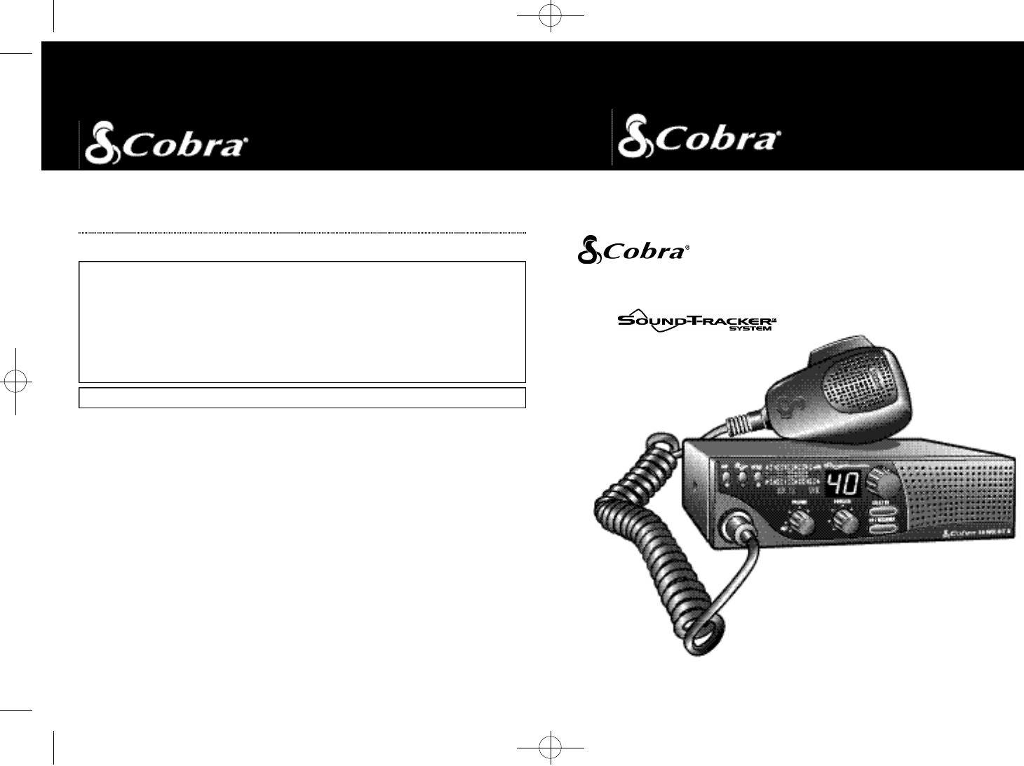
18 WX ST II
Mobile Radio
with System
O pe rating Instru ctions for your
18 WX ST II
18 WX ST.NEW LAYOUT(4279)2a 8/9/00 4:26 PM Page 26
A1
The Citizens Band Story
4
5
21
3
The Ci t i z ens Band lies be tween the shortwave bro a d ca s t
and 10-meter Am ateur radio bands,and was established
by law in 1949. The Class D two - w ay co m m u n i cat i o n s
s e rv i ce was opened in 1959.(CB also includes a Class A
c i t i zens band and Class C re m o t e co nt rol fre q u e n c i e s. )
F CCR e g u l at i o n s
F C C re g u l ations pe rmit only "transmissions" (one-party
to another) rather than" bro a d cast" (to a wide audience ) .
Th u s ,a dve rtising is not allowed on CB channels be ca u s e
t h at is "bro a d ca s t i n g " .
F CC Wa rn i n g s
All tra n s m i t ter adjustments other than those supplied
by the manufact u rer as fro nt panel ope rating co nt ro l s,
must be made by,or under the supe rvision of,the holder
of an FCC-issued general Ra d i o - Telephone Ope r ato r’s
L i ce n s e .
Re p l a ce m e nt or substitution of tra n s i s to r s ,regular di-
odes or other parts of a unique nat u re,with parts other
than those re c ommended by Co b ra ,m ay cause violat i o n
of the te c h n i cal re g u l a tions of Pa rt 95 of the FCC Ru l e s,
or violation of Ty pe Ac ce p t a n ce re q u i re m e nts of Pa r t 2
of the Ru l e s.
You should read and understand Pa rt 95 (included with
this unit) of the FCC Rules and Re g u l at i o n s,be fo r e ope r-
ating your Co b r a ra d i o,even though the FCC no longer
re q u i res you to obtain an ope rato r’s lice n s e.
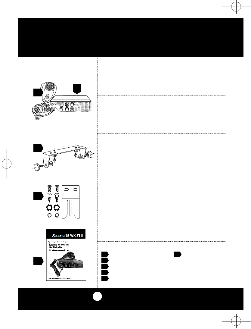
Wh at’s included with your CB Ra d i o :
1 . CB tra n s ce i ve r 6 . F CC ru l e s
2 . Mi c ro p h o n e .(not pict u re d )
3 . Tra n s ce i v er bra c ke t 1 .
4 . Mi c rophone bra c ke t
5 . O pe rating Ma n u a l
18 WX ST.NEW LAYOUT(4279)2a 8/9/00 4:26 PM Page 28
A2
Controls and Indicators
Thank you for purchasing the Cobra 18 WX ST II
CB Radio Transceiver.Properly used,this Cobra
p rod u c t will give you many years of reliable serv i ce.
“Cuts Static coming in,adds Punch going out!”
Technology that dramatically improves the
transmission and reception of CB radio signals.
The revolutionary SoundTrackerTM System recon-
figures the transmission signal which allows it to
be transferred more effectively through cluttered
airwaves.
At the same time,it significantly reduces the
amount of static on all incoming CB signals.
The end result is a clearer,cleaner sounding
reception of signals and a more powerful
transmission which dramatically improve
CB communications.
Customer Support
Should you encounter any problems with this
product,or not understand its many features,
please refer to this owner’s manual. If,after refer-
ring to the manual, you still need help,call Cobra
Customer Service at 773.889.3087.
Cobra Customer Service
Live operators are
available
M-F 8:00 am – 6:00 pm
Central Standard Time at
773.889.3087
Automated Technical
Assistance available 24
hours a day, seven days a
week.E-mail questions to:
productinfo@
cobraelectronics.com
Cobra on the World Wide
Web:Frequently Asked
Questions (FAQ) can be
found at:
w w w. co b ra e l e ct ro n i c s. co m
A3
1
7
1 2 6
2 3 4 5
Our Thanks to You
1 3
1 4
8
1 1
15
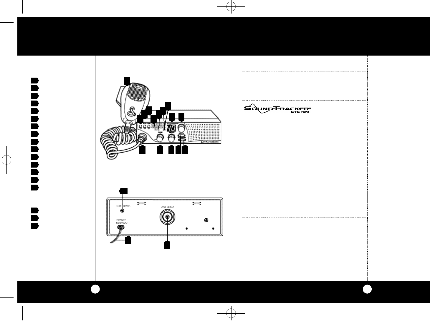
1. Microphone Connector.
2. Off/On/Volume.
3. Squelch.
4. Channel 9/Channel 19
5. CB/Weather
6. Channel Selector Button.
7. LED Channel Display.
8. S/RF Power Meter.
9. WX Indicator LED.
1 0 . TX Indicator LED.
1 1 . RX Indicator LED.
1 2 . Scan Button.
1 3 . SoundTracker™ Button.
1 4 . Dual Watch Button.
1 5 . Microphone
Back Side
1 6 . Antenna Connector
1 7 . External Spe a ker Co n n e cto r
1 8 . Power Cord
9
1 0
16
17
18
18 WX ST.NEW LAYOUT(4279)2a 8/9/00 4:26 PM Page 30