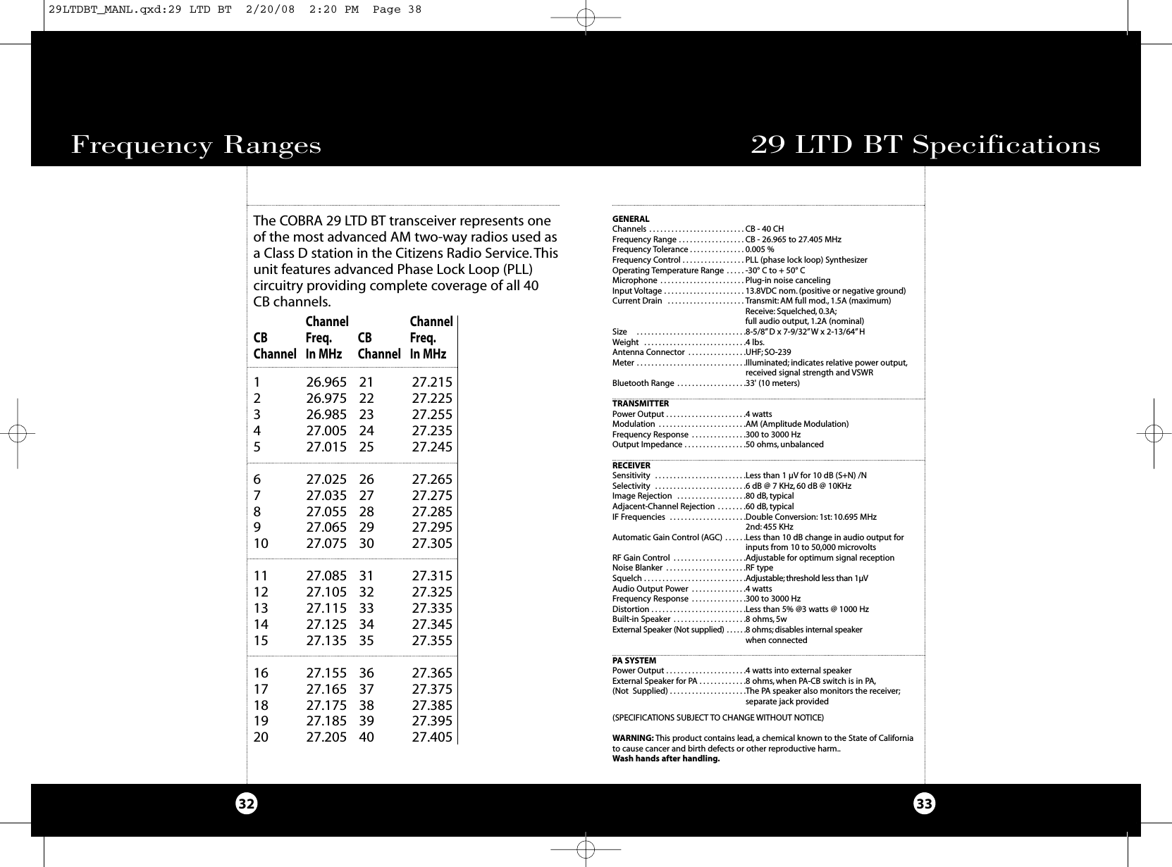
Cobra Electronics 29BT2K8 BLUETOOTH TELEPHONE ACCESORY INSTALLED IN CB TRANSCEIVER User Manual 29LTDBT
Cobra Electronics Corporation BLUETOOTH TELEPHONE ACCESORY INSTALLED IN CB TRANSCEIVER 29LTDBT
UserManual.wiki
>
Cobra Electronics
>
29BT2K8 User Manual
USERS MANUAL
Navigation menu
Upload a User Manual
Namespaces
Wiki Guide
HTML
PDF
Info
Views
User Manual
Discussion / Help
Navigation
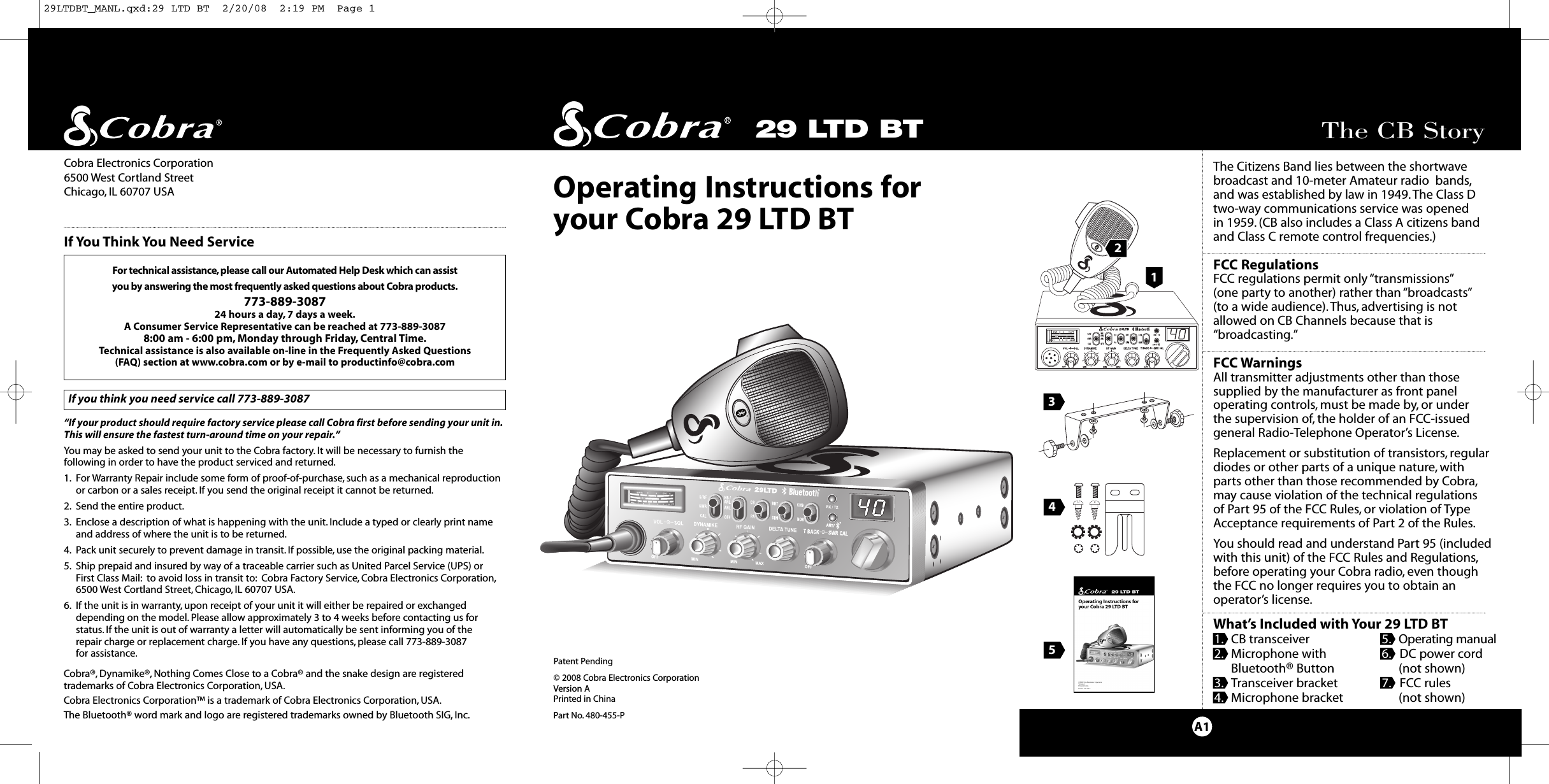
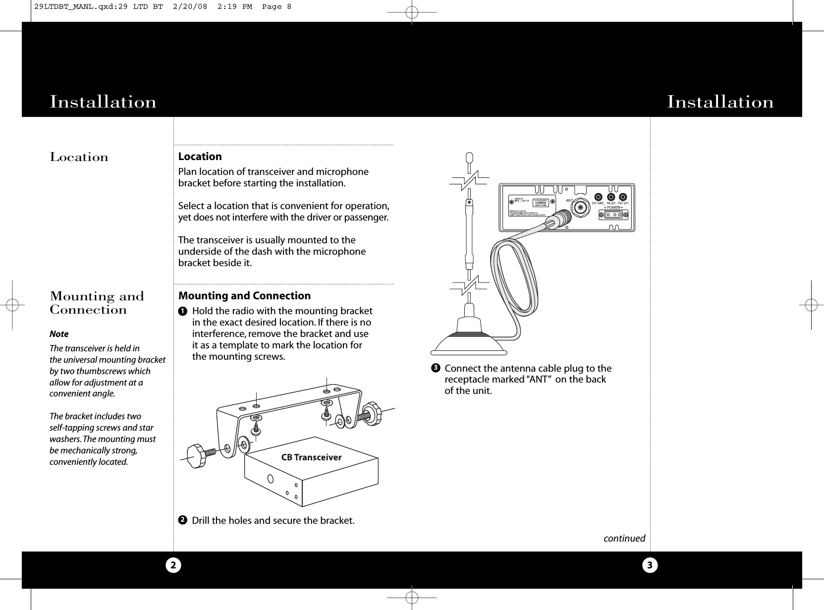
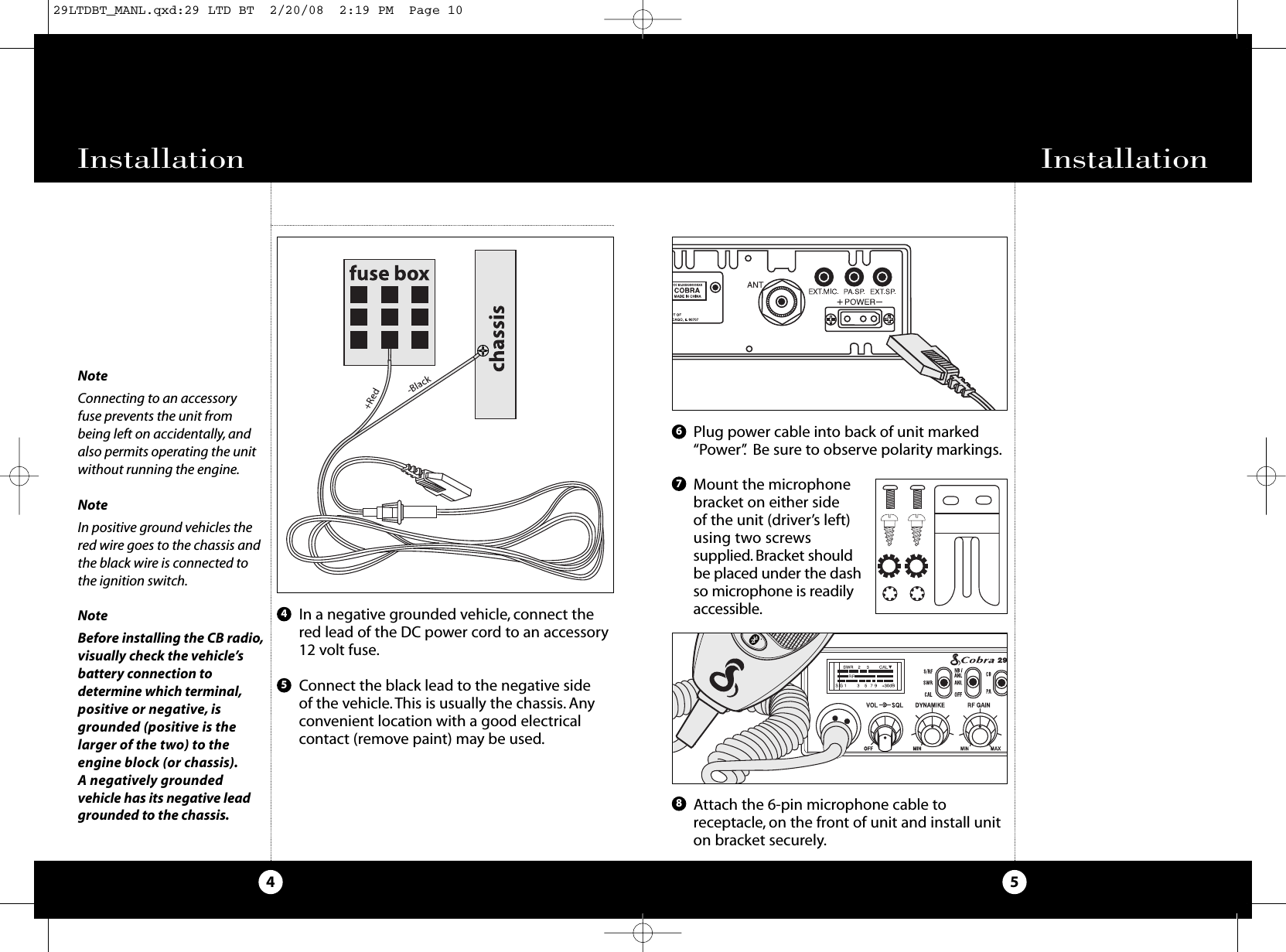
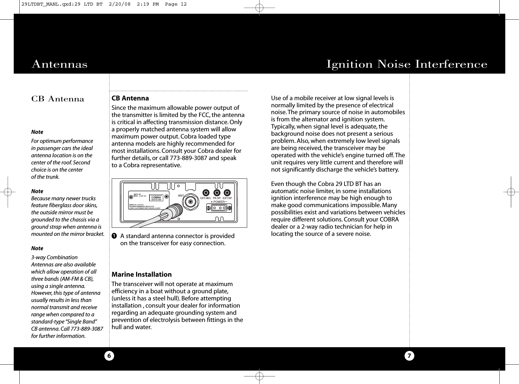
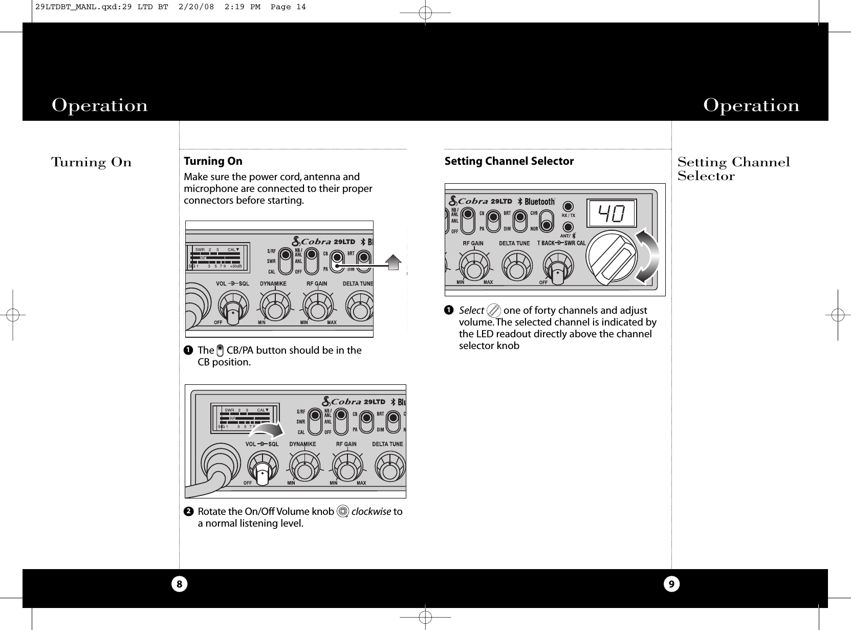
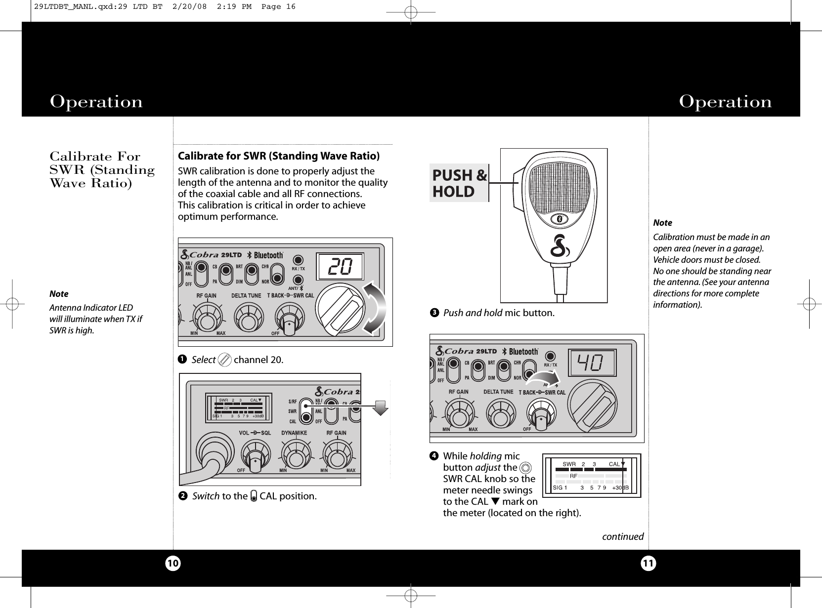
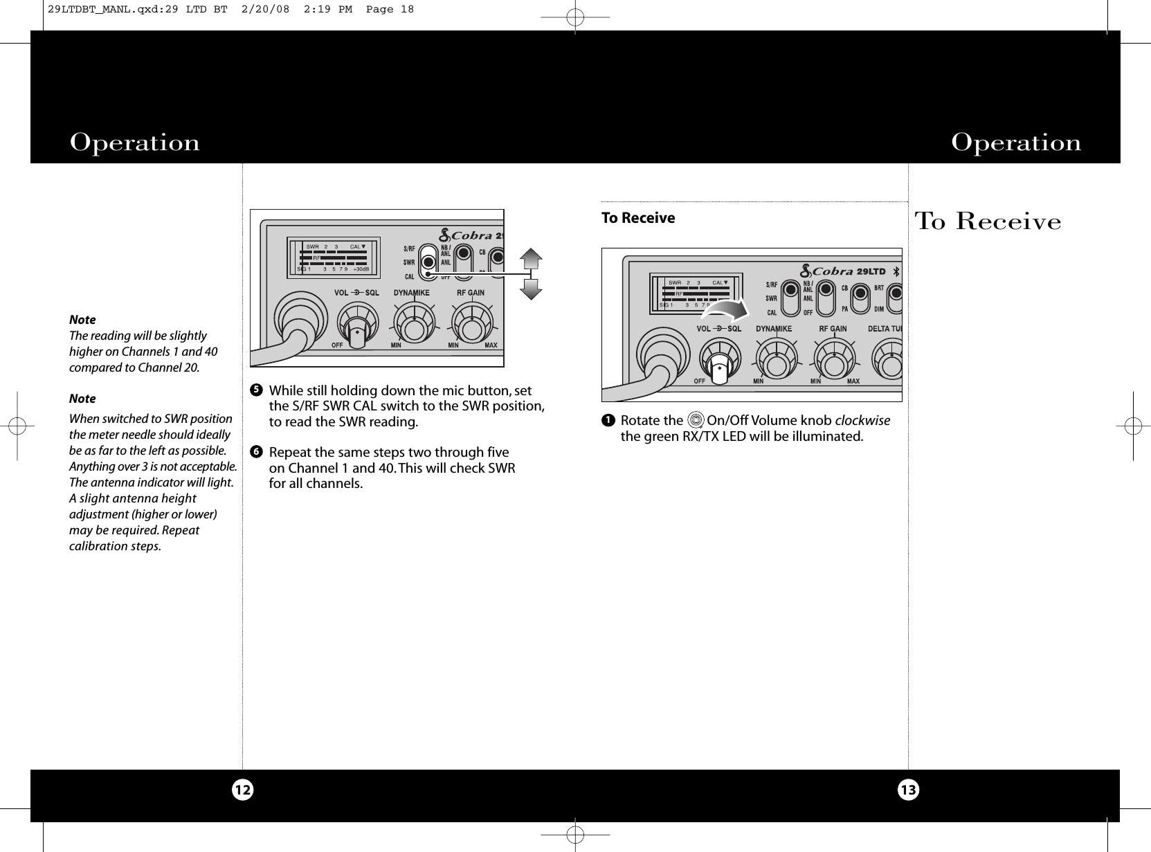
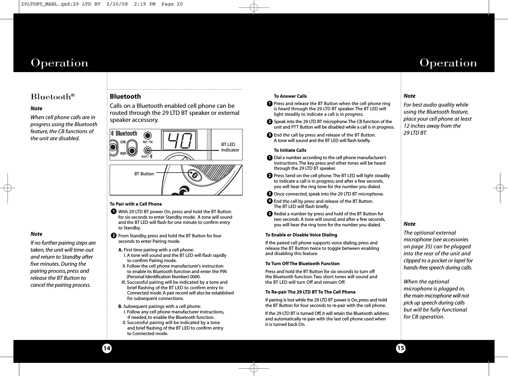
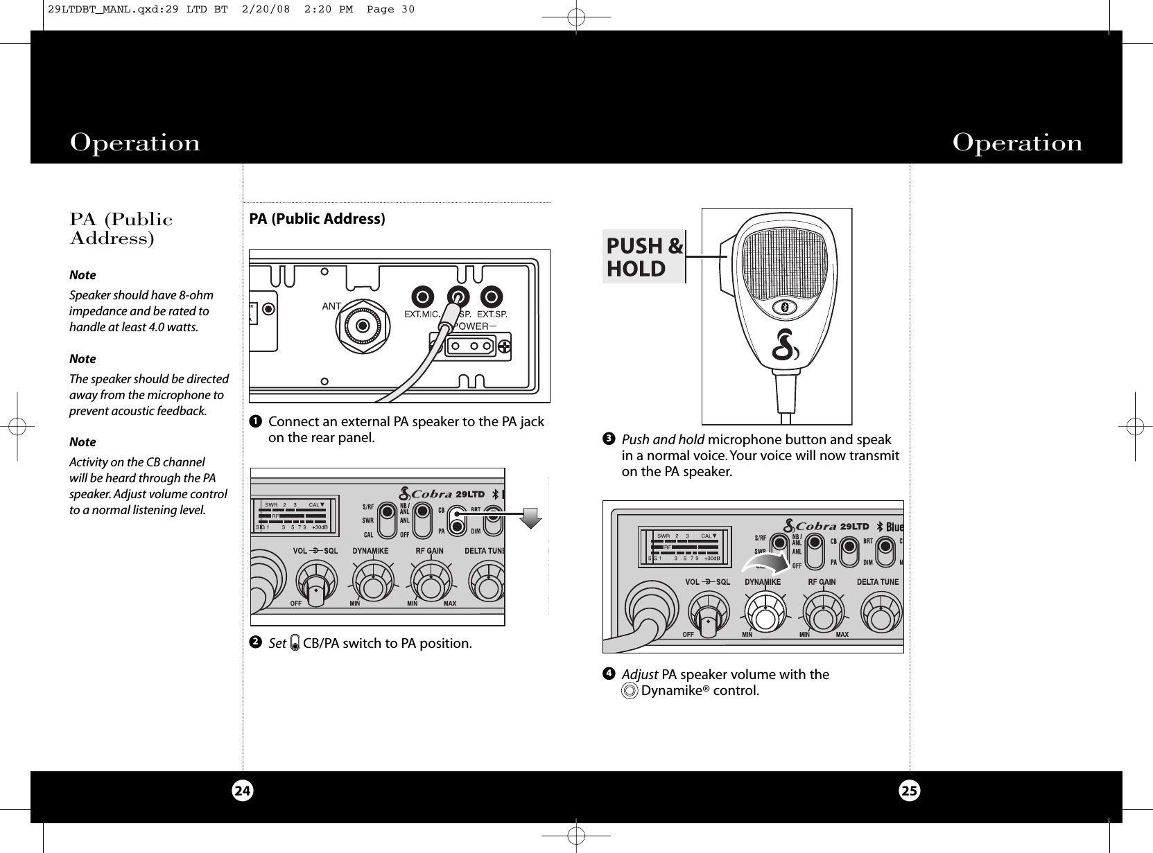
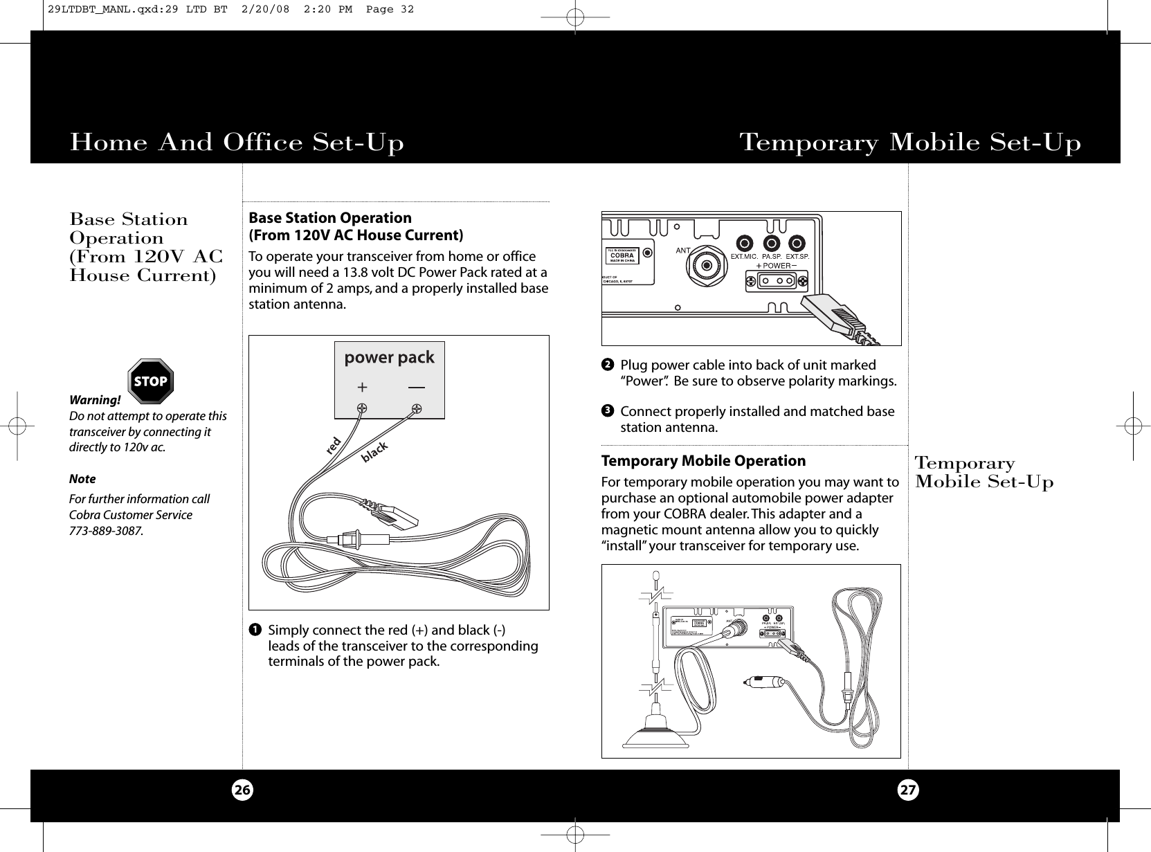
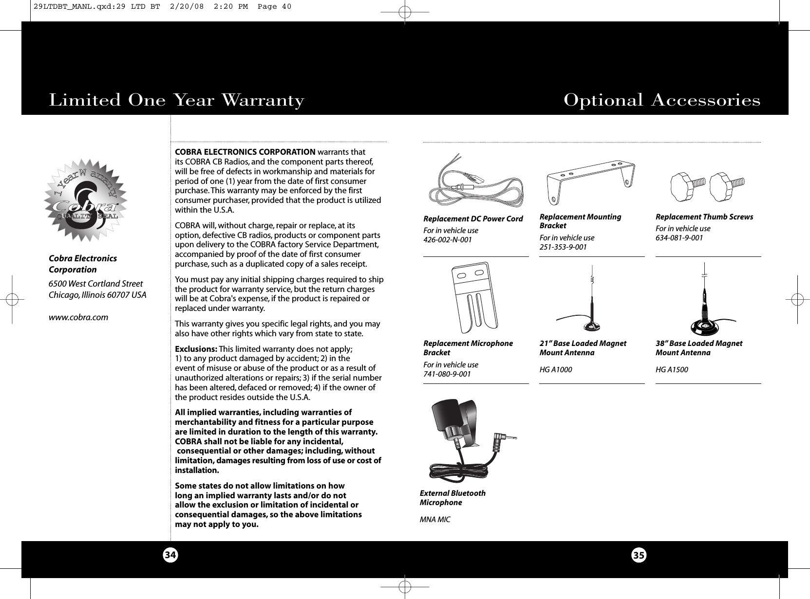
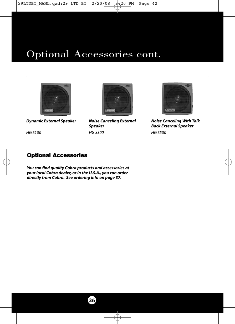
![426-002-N-001 Replacement DC Power Cord251-353-9-001 Replacement Mounting Bracket634-081-9-001 Replacement Thumb Screws741-080-9-001 Replacement Microphone BracketHG A1000 21” Base Loaded,Magnetic Mount AntennaHG A1500 38” Base LoadedMagnetic Mount AntennaMNA MIC External Bluetooth MicrophoneItem # DescriptionAccessory Order Info371. 6-Pin Microphone Connector2. Power On/Off/Volume/Squelch Control3. Dynamike®4. RF Gain5. Delta-Tune6. SWR CAL / Talk Back7. Channel Selector8. LED Channel Display9. ANT Indicator andBluetooth® LED Indicator10. RX (Receive)/ TX (Transmit)LED Indicator11. Channel 9/ Normal Switch12. Dimmer Switch13. CB/PA Switch14. NB/ANL ANL Off Switch15. S/RF SWR CAL Switch16. Signal Strength Meter.17. Microphone.18. Bluetooth ButtonBack Side19. External BluetoothMicrophone Jack20. Public AddressSpeaker Jack21. External Speaker Jack22. Power Jack23. Antenna ConnectorThank you for purchasing the Cobra 29 LTD BT CBRadio. Properly used, this Cobra product will giveyou many years of reliable service.Customer SupportShould you encounter any problems with theproduct or not understand its many features,please refer to this owner’s manual. If , afterreferring to the manual, you still need help,call Cobra Customer Service at 773-889-3087.Controls and IndicatorsCobra Customer ServiceLive operators are availableM-F 8:00 am - 6:00 pm CentralTime at: 773-889-3087Automated Technical Assistanceavailable 24 hours a day, sevendays a week. E-mail questionsto: productinfo@cobra.comCobra on the World Wide Web:Frequently Asked Questions(FAQ) can be found on-line at:www.cobra.comOur Thanks to YouA3A212 3 4 5 6 723 2216 81020 211112131415179Ordering From U.S.A.Call 773-889-3087 for pricing or visit www.cobra.com.For Credit Card OrdersCall 773-889-3087 [Press one from the main menu] 8:00 a.m.to 6:00 p.m. Central Time, Monday through Friday.Make Check or Money Order Payable ToCobra Electronics, Attn: Accessories Dept.,6500 West Cortland Street, Chicago, IL 60707 U.S.A.To Order OnlinePlease visit our website: www.cobra.com181929LTDBT_MANL.qxd:29 LTD BT 2/20/08 2:19 PM Page 4](https://usermanual.wiki/Cobra-Electronics/29BT2K8/User-Guide-931351-Page-2.png)