Cobra Electronics Mrf 80B Users Manual F80 General.qxp
Mrf 80b to the manual 93c834d3-9e80-430b-bfc4-233e296c6d8e
2015-01-24
: Cobra-Electronics Cobra-Electronics-Mrf-80B-Users-Manual-221034 cobra-electronics-mrf-80b-users-manual-221034 cobra-electronics pdf
Open the PDF directly: View PDF ![]() .
.
Page Count: 83
A1 English
Our Thanks to you and
Customer Assistance
Introduction
VHF MARINE RADIO
MR F80B
Printed in China Part No. 480-345P
Owner’s Manual
Nothing Comes Close to a Cobra®
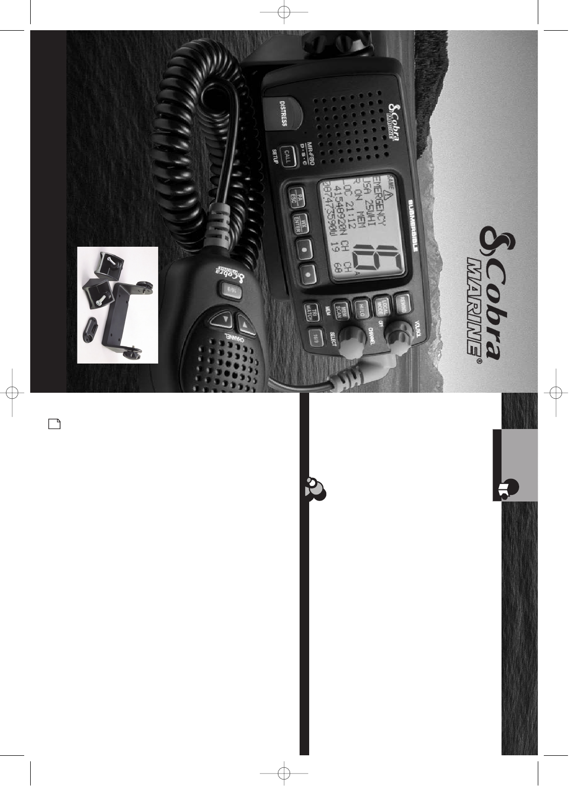
Thank you for purchasing a CobraMarine®VHF radio.
Properly used, this Cobra®product will give you
many years of reliable service.
How Your CobraMarine VHF Radio Works
This radio is a VHF transceiver for fixed mounting on your boat. It gives you 2-way
vessel-to-vessel and vessel-to-shore station communications, primarily for safety
and secondarily for navigation and operational purposes. With it, you can call for
help, get information from other boaters, talk to lock or bridge tenders and make
radiotelephone calls to anywhere in the world through a marine operator.
Besides 2-way communications, in the U.S.A., the radio can provide quick
access to receive all NOAA (National Oceanographic and Atmospheric
Administration), including two Canadian weather channels for alerting you to
weather emergencies with a tone on a weather channel you can select for your area.
Customer Assistance
Should you encounter any problems with this product, or not understand
its many features, please refer to this owner’s manual. If you require further
assistance after reading this manual, Cobra Electronics offers the following
customer assistance services:
For Assistance in the U.S.A.
Automated Help Desk English only.
24 hours a day, seven (7) days a week 773-889-3087 (phone).
Customer Assistance Operators English and Spanish.
8:00 a.m. to 6:00 p.m. Central Time Mon. through Fri. (except holidays)
773-889-3087 (phone).
Questions English and Spanish.
Faxes can be received at 773-622-2269 (fax).
Technical Assistance English only.
www.cobra.com (online: Frequently Asked Questions).
English and Spanish. productinfo@cobra.com (e-mail).
For Assistance Outside the U.S.A.
Contact Your Local Dealer
Customer Assistance
©2007 Cobra Electronics Corporation™
6500 West Cortland Street
Chicago, Illinois 60707 USA
www.cobra.com
F80 Cover.qxp:QXP-1058736909.qxp 12/29/06 9:35 AM Page A1
A3 English
Product Features
Introduction
A2 English
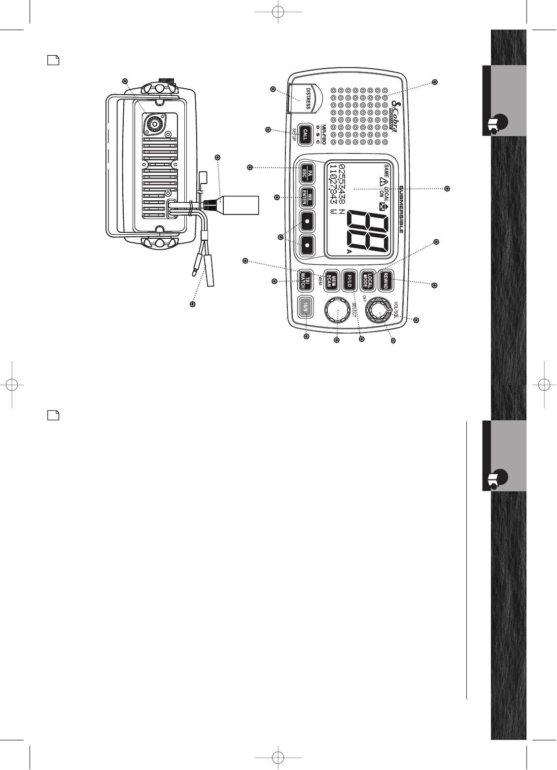
Transceiver Controls,
Indicators and Connections
Introduction
Squelch
Knob
Power
Volume
Knob
Local
Mode
Button
Backlit
LCD
Screen
HI/LO
Power
Button
Rewind
Button
Speaker
Channel
Knob
Tri-Watch
Button
Instant
Channel
16/9
Button
Public
Address/
Escape
Channel
Preset
(Function)
Buttons
Memory Scan/
Memory Clear
Button
Call/Setup
Button
DSC Distress
Button (Behind
Red Spring
Loaded Cover)
Weather/Enter
Button
Power
Connection
Antenna
Socket
Dual Power HI/LO
Selectable to 1 or 25 watts output power
for near or distant calling.
USA/International/Canada Channels
Allows operation on any of the three (3)
different channel maps established for
these areas.
All NOAA Weather Channels
Instant access to all of the National
Weather Channels, 24 hours a day.
Emergency Weather Alert with SAME
Can alert you with an audible
tone and visual alarm if threatening
weather is nearby. The SAME alerts
provide you with additional alerts for
specific local areas.
Instant Channel 16/9
Instant access to the priority
Channel 16 and calling Channel 9.
Digital Selective Calling (DSC)
Allows sending a distress message
at the touch of a button as well as
specific station-to-station calls.
Cobra Exclusive Rewind-Say-Again™
Digital Voice Recorder
A dedicated button allows user to replay
up to the last 20 seconds of audio. Press
the dedicated rewind button and Cobra
VHF will replay the last 20
seconds of the audio from your VHF.
PA (Public Address)
Allows operator instant access to public
address system by pressing button.
Memory Scan
Lets you scan through all selected
memory channels to find conversations
in progress.
Tri-Watch
Lets you monitor three (3) channels
at once — Channel 16, Channel 9 and
one (1) user selectable channel.
Noise Canceling Microphone
Blocks background noise to let your
voice be heard at the receiving station.
Controls on the Microphone
Handy control buttons on the
microphone/speaker let you operate one-
handed at a distance from the radio.
Illuminated Buttons
Helps you quickly find the buttons
you need in low light conditions.
Digital Selective Calling (DSC Class-D)
Allows the ability to maintain a listening
watch on VHF Channel 16 while
simultaneously monitoring Channel 70
for DSC calls. Allows sending a distress
message at the touch of a button as well
as specific station-to-station calls. Radio
utilizes two (2) built-in encoders
(receivers).
Mounting Kits (Included)
Radio can be mounted on, under or in
almost any flat surface using one of
the included brackets.
Product Features •
NMEA and
Auxiliary I/O
Connector
F80 Cover.qxp:QXP-1058736909.qxp 12/29/06 9:35 AM Page A2
Waterproof
Submersible to 3.28 ft (1 m) of water
for 30 minutes — meets JIS7
Standards.
Local Mode
A dedicated button that allows user to
lower unnecessary noise interference
from random RF noise in highly
populated areas.
Distress Call Button
Allows sending a distress message at the
touch of a button as well as specific
station-to-station calls.
NMEA Port for GPS, Chartplotter and
DSC Interfacing
The NMEA “IN” input in this radio will
receive GPS position information from all
GPS devices (e.g., Chartplotters, GPS
sensors) sending out their position
information using the standard NMEA
0183 protocol. This position information
from the GPS is then sent by the MR F80
when sending out DSC emergency
transmissions. This unit also has an
NMEA “OUT” output. This allows the
radio to send out position information
received from other VHF radio units. This
enables position polling and other
advanced integration.
A4 English
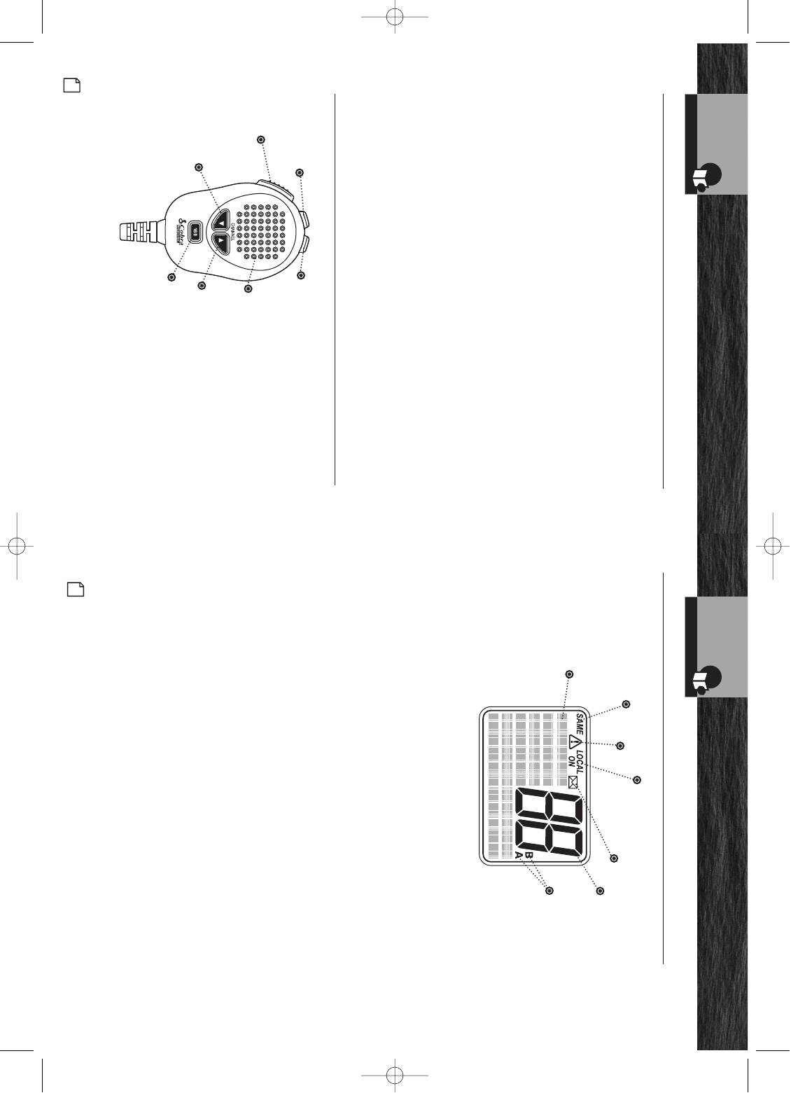
Microphone/Speaker and
Product Features (continued)
Introduction
Up
Button
Microphone
Call/Setup
Enter
Button
Down
Button
Push to
Talk
(PTT)
Button
Function
(F1/F2)
Button
Instant
Channel
16/9 Button
Up/Down Buttons
Can be used instead of
those on the transceiver.
Instant Channel
16/9 Button
Can be used instead of
the one on the transceiver.
Function Button
Allows the user to “toggle”
between selected working
channel and favorite “Pre-
Set” channels to access
your most frequently used
channels directly from the
microphone.
Microphone/Speaker with Auxiliary Controls •
Product Features •
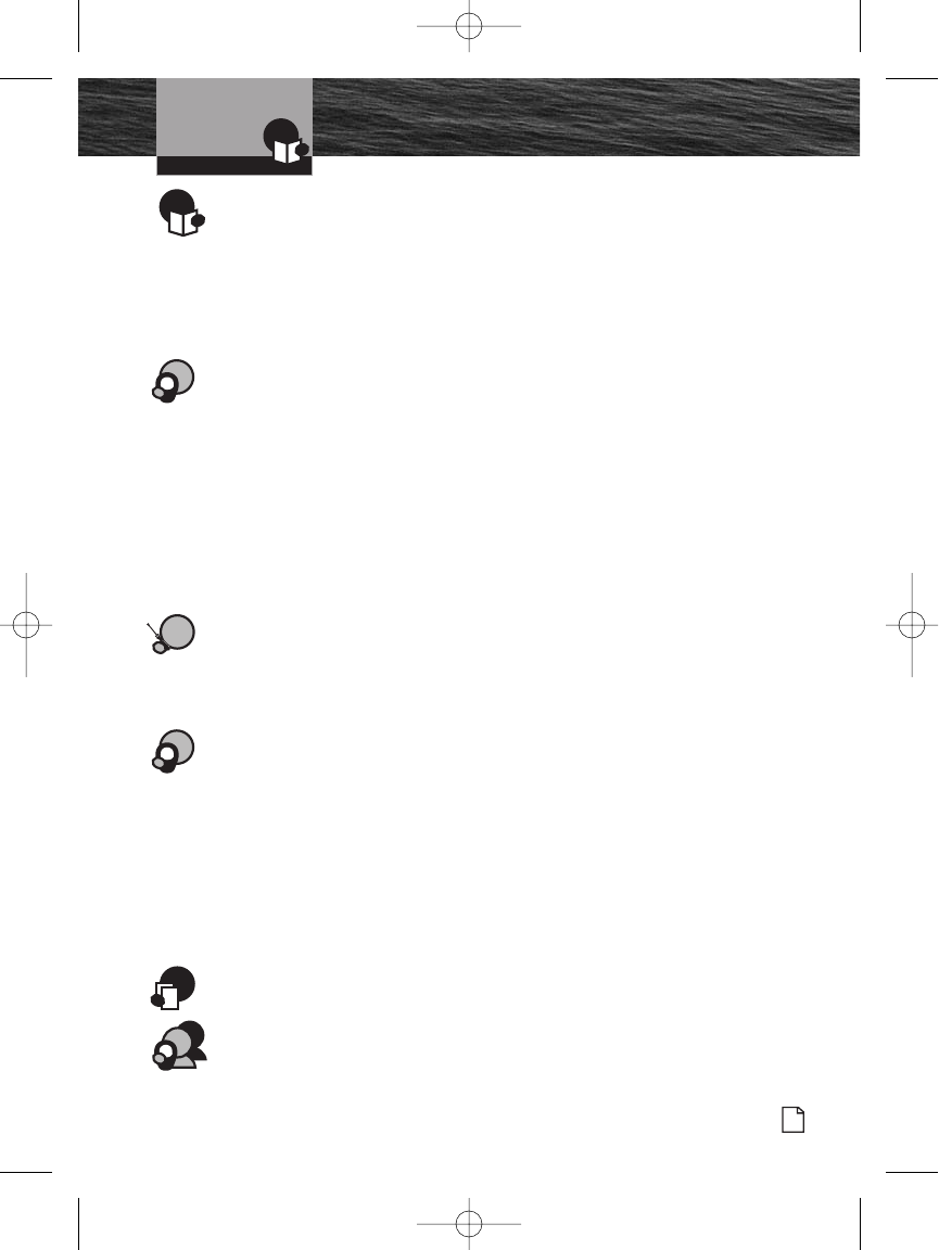
Backlit LCD (Liquid Crystal
Display) Screen
Introduction
Weather
Alert
Icon Call Log
Icon
LOCAL ON
Radio
Sensitivity
Icon Active
Channel
Number
Radio Status
and Data
Display Fields
Backlit LCD (Liquid Crystal Display) Screen •
Extended
Channel Number
Alpha
Designators
SAME Alert Icons
A5 English
F80 Cover.qxp:QXP-1058736909.qxp 12/29/06 9:36 AM Page A3
Introduction
Nothing Comes Close to a Cobra®
Table Of Contents
1
Introduction
Our Thanks to You . . . . . . . . . . . . . . . . . . . . . . . . . . . . . . . . . . . . . . . . . . . . . . . . . . . A1
Customer Assistance . . . . . . . . . . . . . . . . . . . . . . . . . . . . . . . . . . . . . . . . . . . . . . . . . A1
Transceiver Controls, Indicators and Connections . . . . . . . . . . . . . . . . . . . . . . . . . . . A2
Product Features . . . . . . . . . . . . . . . . . . . . . . . . . . . . . . . . . . . . . . . . . . . . . . . . . . . . . A3
Microphone/Speaker with Auxiliary Controls . . . . . . . . . . . . . . . . . . . . . . . . . . . . . . . A4
Backlit LCD (Liquid Crystal Display) Screen . . . . . . . . . . . . . . . . . . . . . . . . . . . . . . . .A5
Important Safety Information . . . . . . . . . . . . . . . . . . . . . . . . . . . . . . . . . . . . . . . . . . . . 2
Recommendations for Marine Communication . . . . . . . . . . . . . . . . . . . . . . . . . . . . . . . 4
VHF Marine Radio Protocols
FCC Licensing Information . . . . . . . . . . . . . . . . . . . . . . . . . . . . . . . . . . . . . . . . . . . . . . 5
VHF Marine Radio Procedures . . . . . . . . . . . . . . . . . . . . . . . . . . . . . . . . . . . . . . . . . . . 6
Voice Calling . . . . . . . . . . . . . . . . . . . . . . . . . . . . . . . . . . . . . . . . . . . . . . . . . . . . . . . . . 7
Digital Selective Calling (DSC) . . . . . . . . . . . . . . . . . . . . . . . . . . . . . . . . . . . . . . . . . . . 8
Maritime Mobile Service Identity (MMSI) . . . . . . . . . . . . . . . . . . . . . . . . . . . . . . . . . . . 9
Radiotelephone Calls . . . . . . . . . . . . . . . . . . . . . . . . . . . . . . . . . . . . . . . . . . . . . . . . . . 10
Emergency Messages Distress Procedure . . . . . . . . . . . . . . . . . . . . . . . . . . . . . . . . . 11
Marine Distress Procedure – DSC . . . . . . . . . . . . . . . . . . . . . . . . . . . . . . . . . . . . . . . . 13
VHF Marine Channel Assignments . . . . . . . . . . . . . . . . . . . . . . . . . . . . . . . . . . . . . . . 14
NOAA Weather Channels and Alert . . . . . . . . . . . . . . . . . . . . . . . . . . . . . . . . . . . . . . . 24
World City Time Zones . . . . . . . . . . . . . . . . . . . . . . . . . . . . . . . . . . . . . . . . . . . . . . . . 25
Installation and Start-Up
Included in this Package . . . . . . . . . . . . . . . . . . . . . . . . . . . . . . . . . . . . . . . . . . . . . . . 26
Mounting and Powering the Radio . . . . . . . . . . . . . . . . . . . . . . . . . . . . . . . . . . . . . . . 27
Antenna Requirements and Attachment . . . . . . . . . . . . . . . . . . . . . . . . . . . . . . . . . . . 31
External Devices and Connections . . . . . . . . . . . . . . . . . . . . . . . . . . . . . . . . . . . . . . . 33
Operating Your Radio
Getting Started . . . . . . . . . . . . . . . . . . . . . . . . . . . . . . . . . . . . . . . . . . . . . . . . . . . . . . 36
Setup Mode Programming . . . . . . . . . . . . . . . . . . . . . . . . . . . . . . . . . . . . . . . . . . . . . 41
Special Features . . . . . . . . . . . . . . . . . . . . . . . . . . . . . . . . . . . . . . . . . . . . . . . . . . . . . .45
Voice Transmission . . . . . . . . . . . . . . . . . . . . . . . . . . . . . . . . . . . . . . . . . . . . . . . . . . . 47
NOAA All Hazards/Weather Radio and Alert, w/SAME . . . . . . . . . . . . . . . . . . . . . . . . . 50
Advanced Operation . . . . . . . . . . . . . . . . . . . . . . . . . . . . . . . . . . . . . . . . . . . . . . . . . . 53
Digital Select Calling (DSC) SetUp . . . . . . . . . . . . . . . . . . . . . . . . . . . . . . . . . . . . . . . 58
Digital Select Calling (DSC) Operation . . . . . . . . . . . . . . . . . . . . . . . . . . . . . . . . . . . . 63
Maintenance . . . . . . . . . . . . . . . . . . . . . . . . . . . . . . . . . . . . . . . . . . . . . . . . . . . . . . . . 76
Troubleshooting . . . . . . . . . . . . . . . . . . . . . . . . . . . . . . . . . . . . . . . . . . . . . . . . . . . . . 76
Specifications . . . . . . . . . . . . . . . . . . . . . . . . . . . . . . . . . . . . . . . . . . . . . . . . . . . . . . . 77
Warranty and Trademark
Limited 3-Year Warranty . . . . . . . . . . . . . . . . . . . . . . . . . . . . . . . . . . . . . . . . . . . . . . . 78
Trademark Acknowledgement . . . . . . . . . . . . . . . . . . . . . . . . . . . . . . . . . . . . . . . . . . .78
Customer Service
Product Service . . . . . . . . . . . . . . . . . . . . . . . . . . . . . . . . . . . . . . . . . . . . . . . . . . . . . . 79
Flush Mount Template . . . . . . . . . . . . . . . . . . . . . . . . . . . . . . . . . . . . . . . . . . . . . . . . . 80
F80 General.qxp:QXP-1058731464.qxp 12/29/06 9:06 AM Page 1
2English
Important Safety Information
Introduction
Important Safety Information •
Before installing and using your CobraMarine VHF radio,
please read these general precautions and warnings.
Warning and Notice Statements
To make the most of this radio, it must be installed and used properly.
Please read the installation and operating instructions carefully before
installing and using the radio. Special attention must be paid to the WARNING
and NOTICE statements in this manual.
WARNING
Statements identify conditions that could result in personal injury or loss of life.
NOTICE
Statements identify conditions that could cause damage to the radio
or other equipment.
Safety Training Information
This CobraMarine®radio is designed for, and classified as, “Occupational Use Only.”
The radio must only be used in the course of employment by individuals aware of
both the hazards and the ways to minimize those hazards. This radio is NOT
intended for use in an uncontrolled environment by the “General Population.”
This radio has been tested and complies with the FCC RF exposure limits for
“Occupational Use Only.” This CobraMarine VHF radio also complies with the
following guidelines and standards regarding RF energy and electromagnetic
energy levels as well as evaluation of those levels for human exposure:
FCC OET Bulletin 65 Edition 97-01 Supplement C, Evaluating
Compliance with FCC Guidelines for Human Exposure to Radio
Frequency Electromagnetic Fields.
American National Standards Institute (C95.1-1992), IEEE Standard
for Safety Levels with Respect to Human Exposure to Radio Frequency
Electromagnetic Fields, 3 kHz to 300 GHz.
American National Standards Institute (C95.3-1992), IEEE
Recommended Practice for the Measurement of Potentially
Hazardous Electromagnetic Fields — RF and Microwave.
F80 General.qxp:QXP-1058731464.qxp 12/29/06 9:06 AM Page 2
Introduction
Nothing Comes Close to a Cobra®
Important Safety Information
3
The following WARNINGS and NOTICE information will make you aware of RF
exposure hazards and how to assure you operate the radio within the FCC RF
exposure limits established for the radio.
WARNINGS
Your radio generates electromagnetic RF (radio frequency) energy when
it is transmitting. To ensure that you and those around you are not exposed
to excessive amounts of that energy, DO NOT touch the antenna when
transmitting and KEEP yourself and all others on your vessel the required
distance away from the antenna while transmitting. See page 31 in the
antenna requirements section for further information.
DO NOT operate the radio without a proper antenna or equivalent
dummy load attached. Doing so may expose you to excessive RF
energy and will damage the radio.
DO NOT transmit more than 50% of the time the radio is in use —
50% duty cycle. The radio is transmitting when the Talk button is
pressed and the transmit information shows on the LCD screen.
ALWAYS use only Cobra authorized accessories.
DO NOT operate the radio in an explosive atmosphere, near blasting sites,
or in any area where signs are posted prohibiting radio transmissions.
NEVER connect the transceiver to AC power. It can be a fire hazard, may
cause an electric shock and may damage the transceiver.
NEVER mount the transceiver or microphone/speaker where they might
interfere with operation of your vessel or cause injury.
DO NOT allow children or anyone unfamiliar with proper procedures to
operate the radio without supervision.
Failure to observe any of these warnings may cause you to exceed
FCC RF exposure limits or create other dangerous conditions.
NOTE
Throughout this manual, the term “Transceiver” will be used to identify the
main unit containing the LCD screen and controls. The term “Radio” will be
used to identify the entire equipment including transceiver, microphone,
antenna and any attached external speakers.
F80 General.qxp:QXP-1058731464.qxp 12/29/06 9:06 AM Page 3
4English
Recommendations for
Marine Communication
NOTICE
AVOID using or storing the radio at temperatures below -4°F (-20°C) or
above 140°F (60°C).
NEVER connect the transceiver to DC power greater than 16 volts or to
any DC source with reversed polarity. Doing so will damage the transceiver.
DO NOT cut the power cables attached to the transceiver. Improper
reconnection with reversed polarity will damage the transceiver.
POSITION your radio, external speakers and cables at least 3 ft (0,9 m) away from
your vessel’s magnetic navigation compass. CHECK your compass before and
after installation to be sure that it has not introduced any deviation.
DO NOT attempt to service any internal parts yourself. Have any
necessary service performed by a qualified technician.
DO NOT drop the transceiver or microphone/speaker. Doing so may
crack the case or damage a waterproof seal. Once these items have
been dropped, the original waterproofing cannot be guaranteed.
DO NOT use chemicals or solvents such as mineral spirits and alcohol
to clean your radio. They may damage the case surfaces.
Changes or modifications to your radio MAY VOID its compliance with FCC (Federal
Communication Commission) rules and make it illegal to use.
Recommendations for Marine Communication •
The frequencies your radio uses are set aside to enhance safety afloat and for
vessel navigation and operational messages over a range suitable for near-shore
voyages. If the 25 watt maximum output of your radio is not sufficient for the
distances you travel from the coast, consider installing a more powerful radio such
as HF single-side band or satellite radio for your vessel.
The U.S. Coast Guard does not endorse cellular telephones as substitutes for
marine radios. They generally cannot communicate with rescue vessels and,
if you make a distress call on a cellular telephone, only the party you call will
be able to hear you. Additionally, cellular telephones may have limited coverage
over water and can be hard to locate. If you do not know where you are, the
Coast Guard will have difficulty finding you if you are using a cellular telephone.
However, cellular telephones can have a place onboard where cellular coverage
is available — to allow social conversations and keep the marine frequencies
uncluttered and available for their intended use.
Introduction
F80 General.qxp:QXP-1058731464.qxp 12/29/06 9:06 AM Page 4
Nothing Comes Close to a Cobra®
FCC Licensing Information
5
FCC Licensing Information •
CobraMarine VHF radios comply with the FCC (Federal Communication Commission)
requirements that regulate the Maritime Radio Service.
This CobraMarine radio incorporates a VHF FM transceiver designed for use in
the frequency range of 156.025 to 163.275 MHz. It requires 13.8 volts DC and
has a switchable RF output power of one (1) or 25 watts.
The radio is capable of Class-D DSC (Digital Selective Calling) operation.
The radio operates on all currently allocated marine channels and is switchable for
use according to U.S.A., International, or Canadian regulations. It features instant
access to emergency Channel 16 and calling Channel 9 as well as NOAA (National
Oceanic and Atmospheric Administration) All Hazards Radio with Alert that can be
accessed by pressing one key.
Station License
An FCC ship station license is no longer required for any vessel traveling in U.S.A.
waters which uses a VHF marine radio, RADAR, or EPIRB (Emergency Position
Indicating Radio Beacon), and which is not required to carry radio equipment.
However, any vessel required to carry a marine radio on an international voyage,
carrying a HF single side band radiotelephone, or carrying a marine satellite
terminal must obtain a station license.
FCC license forms and applications for ship and land stations can be downloaded
through the Internet at www.fcc.gov/formpage.html. Forms can also be obtained by
calling the FCC at 888-225-5322.
International Station License
If your vessel will be entering the sovereign waters of a country other than the
U.S.A. or Canada, you should contact that country’s communications regulatory
authority for licensing information.
Radio Call Sign
Currently, the FCC does not require recreational boaters to have a license. The United
States Coast Guard recommends that the boat’s registration number and state of registry
(e.g., IL 1234 AB) be used as a call sign and be clearly visible on the vessel.
Canadian Ship Station License
You need a Radio Operator’s Certificate if your vessel is operated in Canadian waters.
Radio Operator training and certification is available from the Canadian Power
Squadron. Visit their website (http://www.cps-ecp.ca/english/newradiocard.html),
contact the nearest field office or write: Industry of Canada, Radio Regulatory
Branch, Attn: DOSP, 300 Slater Street, Ottawa, Ontario, Canada K1A 0C8.
VHF Marine Radio Protocols
F80 General.qxp:QXP-1058731464.qxp 12/29/06 9:06 AM Page 5
6English
VHF Marine Radio
Procedures
User Responsibility and Operating Locations
All users are responsible for observing domestic and foreign government
regulations and are subject to severe penalties for violations. The VHF frequencies
on your radio are reserved for marine use and require a special license to operate
from land, including when your boat is on its trailer.
NOTE
This device complies with part 15 of the FCC Rules. Operation is
subject to the following two (2) conditions: 1. This device may not cause
harmful interference, and 2. This device must accept any interference
received, including interference that may cause undesired operation.
FCC Warnings: Replacement or substitution of transistors, regular diodes
or other parts of a unique nature, with parts other than those recommended
by Cobra may cause a violation of the technical regulations of part 80 of the
FCC Rules, or violation of type acceptance requirements of part 2 of the rules.
VHF Marine Radio Procedures •
Maintain Your Watch
Whenever your boat is underway, the radio must be turned On and
be tuned to Channel 16, except when being used for messages.
Power
Try 1 watt first if the station being called is within a few miles. Try a second call
after waiting two (2) minutes. If there is no answer, switch to a higher power. This
will conserve your battery and minimize interference to other users by avoiding
repeated calls.
Calling Coast Stations
Call a coast station on its assigned channel. You may use Channel 16
when you do not know the assigned channel.
Calling Other Vessels
Call other vessels on Channel 16 or on Channel 9. (Channel 9 is preferred
for recreational vessel use.) You may also call on ship-to-ship channels
when you know that the vessel is listening on a ship-to-ship channel.
Initial Calling on Channel 16 or 9
The use of Channel 16 is permitted for making initial contact (hailing) with another
vessel. The limits on calling must be followed. Be reminded, Channel 16’s most
important function is for Emergency Messages. If, for some reason, Channel 16 is
congested, the use of Channel 9, especially in U.S. waters, may be used as the initial
contact (hailing) channel for non-emergency communication.
VHF Marine Radio Protocols
F80 General.qxp:QXP-1058731464.qxp 12/29/06 9:06 AM Page 6
Nothing Comes Close to a Cobra®
Voice Calling
7
Limits on Calling
You must not call the same station for more than 30 seconds at a time.
If you do not get a reply, wait at least two (2) minutes before calling again.
After three (3) calling periods, wait at least 15 minutes before calling again.
Change Channels
After contacting another station on a calling channel, change immediately
to a channel which is available for the type of message you want to send.
Station Identification
Identify, in English, your station by your FCC call sign, vessel name and the state
registration number, at both the beginning and at the end of the message.
Prohibited Communications
You MUST NOT transmit:
False distress or emergency messages.
Messages containing obscene, indecent or profane language.
General calls, signals or messages (messages not addressed to a particular
station) on Channel 16, except in an emergency or if you are testing your radio.
When you are on land.
Voice Calling •
To Call Another Vessel or Shore Installation (e.g. Lock or Bridge Tender):
Make sure your radio is On.
Select Channel 16 and listen to make sure it is not being used.
NOTE
Channel 9 may be used by recreational vessels for general-purpose
calling. This frequency should be used whenever possible to relieve
congestion on Channel 16.
When the channel is quiet, press the Talk button and call the vessel you wish
to call. (Hold the microphone/speaker a few inches from your face and speak
directly into it in a normal tone of voice — clearly and distinctly.) Say “[name
of station being called] THIS IS [your vessel’s name or call sign].”
Once contact is made on the calling channel, you must switch to a proper
working channel. See the channel listing on page 14 through 15.
VHF Marine Radio Protocols
F80 General.qxp:QXP-1058731464.qxp 12/29/06 9:06 AM Page 7
8English
Digital Selective Calling (DSC)
The vessel Corsair calling the vessel Vagabond:
Corsair: “Vagabond, this is Corsair (station license number call sign).”
Vagabond: “Corsair, this is Vagabond. Over.”
Corsair: “Vagabond go to working Channel 68. Over.”
Both parties switch over to the agreed upon working channel....
Corsair: “Vagabond I need to talk to you about... Over.”
Vagabond: “Corsair in answer to your question about... Over.”
Corsair: “Vagabond, thanks for the information about... (call sign and out).”
After each transmission, say “OVER” and release the microphone Push to Talk (PTT)
button. This confirms that the transmission has ended. When all communication with
the other vessel is totally completed, end the message by stating your call sign and the
word “OUT.” Remember, it is not necessary to state your call sign with each
transmission, only at the beginning and end of the message.
NOTE
For best sound quality at the shore station or other vessel receiving your call,
hold the microphone/speaker at least 2 in. (51 mm) from your mouth and
slightly off to one (1) side. Speak in a normal tone of voice.
Digital Selective Calling (DSC) •
Digital selective calling (DSC) is a semi-automated system for establishing a radio
call. It has been designed by the International Maritime Organization (IMO)
as an international standard for VHF, MF and HF calls and is part of the
Global Maritime Distress and Safety System (GMDSS).
DSC will eventually replace aural (listening) watches on distress frequencies
and will be used to announce routine and urgent maritime safety information
broadcasts. Until DSC is fully implemented, it is still necessary to maintain a
listening watch on Channel 16.
The DSC system allows mariners to instantly send a distress call with GPS
position coordinates (requires a GPS receiver to be connected to the radio)
to the Coast Guard and other vessels within range of the transmission.
DSC also allows mariners to initiate and receive distress, urgent, safety,
routine, position request, position send and group calls between vessels
equipped with DSC capable radios.
VHF Marine Radio Protocols
For Example
F80 General.qxp:QXP-1058731464.qxp 12/29/06 9:06 AM Page 8
Nothing Comes Close to a Cobra®
Maritime Mobile
Service Identity (MMSI)
9
VHF Marine Radio Protocols
Maritime Mobile Service Identity (MMSI) •
An MMSI is a nine (9) digit number used on a marine radio capable of using digital
selective calling (DSC). It is used to selectively call other vessels or shore stations
and is similar to a telephone number.
For your CobraMarine radio to operate in the DSC mode, you must enter your
Maritime Mobile Service Identity (MMSI) number. See page 62 for instructions
on how to enter your number.
MMSI Numbers are available in the U.S.A. from these Sources:
Boat U.S.: 800-563-1536 – www.boatus.com/mmsi
Maritel: 888-Maritel (888-627-4835)
Sea Tow International: 631-765-3660 – www.seatow.com
In Canada, Contact:
Industry Canada Spectrum Management Office (only available on the Internet):
http://strategis.ic.gc.ca/epic/internet/insmt-gst.nsf/vwGeneratedInterE/sf01742e.html
To Obtain an MMSI Number Outside the U.S.A.:
Users can obtain an MMSI from their country’s telecommunications authority
or ship registry. This may involve amending or obtaining a ship station license.
WARNING
This equipment is designed to generate a digital maritime distress and
safety signal to facilitate search and rescue. To be effective as a safety
device, this equipment must be used only within communication range
of a shore-based VHF marine channel to distress and safety watch system.
The range of the signal may vary, but under normal conditions should be
approximately 20 nautical miles.
F80 General.qxp:QXP-1058731464.qxp 12/29/06 9:06 AM Page 9
10 English
Radiotelephone Calls
Radiotelephone Calls •
Boaters may make and receive radiotelephone calls to and from any number on
the telephone network by using the services of public coast stations. Calls can be
made — for a fee — between your radio and telephones on land, sea and in the air.
See pages 14 through 23 for the public correspondence (marine operator) channels.
If you plan to use these services, consider registering with the operator of the
public coast station that you plan to work through. Those services can provide
you with detailed information and procedures to follow.
NOTICE
You may disclose privileged information during a radiotelephone call.
Keep in mind that your transmission is NOT private, as it is on a regular
telephone. Both sides of the conversation are being broadcast and can be
heard by anyone who has a radio and tunes to the channel you are using.
VHF Marine Radio Protocols
F80 General.qxp:QXP-1058731464.qxp 12/29/06 9:06 AM Page 10
MAYDAY
PAN
SECURITE
Nothing Comes Close to a Cobra®
Emergency Messages
and Distress Procedure
11
Emergency Messages and Distress Procedure •
The ability to summon assistance in an emergency is the primary reason
to have a VHF marine radio. The marine environment can be unforgiving,
and what may initially be a minor problem can rapidly develop into a
situation beyond your control.
The Coast Guard monitors Channel 16, responds to all distress calls, and
coordinates all search and rescue efforts. Depending on the availability of
other capable vessels or commercial assistance operators in your vicinity,
Coast Guard or Coast Guard Auxiliary craft may be dispatched.
In any event, communicate with the Coast Guard as soon as you experience
difficulties and before your situation becomes an emergency. Use the emergency
message procedures only after your situation has become grave or you are faced
with a sudden danger threatening life or property and requiring immediate help.
Use Channel 16 to communicate your emergency message. Make sure you transmit
on high power. If you are merely out of gas, do not send an emergency message.
Drop your anchor and call a friend or marina to bring the fuel you need or to give
you a tow.
Marine Emergency Signals
The three (3) spoken international emergency signals are:
The distress signal MAYDAY is used to indicate that a station is threatened
by grave and imminent danger and requests immediate assistance.
The urgency signal PAN is used when the safety of the vessel or person
is in jeopardy. (This signal is properly pronounced pahn.)
The safety signal SECURITE is used for messages about the safety of navigation or
important weather warnings. (This signal is properly pronounced see-cure-ee-tay.)
When using an international emergency signal, the appropriate
signal is to be spoken three (3) times prior to the message.
VHF Marine Radio Protocols
F80 General.qxp:QXP-1058731464.qxp 12/29/06 9:07 AM Page 11

12 English
Emergency Messages
and Distress Procedure
If You Hear a Distress Call
You must give any message beginning with one (1) of these signals priority
over any other messages. ALL stations MUST remain silent on Channel 16
for the duration of the emergency unless the message relates directly to
the emergency.
If you hear a distress message from a vessel, stand by your radio. If it is
not answered, YOU should answer. If the distressed vessel is not nearby,
wait a short time for others who may be closer to acknowledge. Even if
you cannot render direct assistance, you may be in a position to relay
the message.
Marine Distress Procedure
Speak slowly — clearly — calmly.
1. Make sure your radio is On.
2. Select Channel 16.
3. Press Talk button and say:
“MAYDAY — MAYDAY — MAYDAY.”
(Or “PAN — PAN — PAN,”
or “SECURITE — SECURITE — SECURITE.”)
4. Say:
“THIS IS [your vessel name or call sign],” repeated three (3) times.
5. Say:
“MAYDAY (or “PAN” or “SECURITE”)
[your vessel name or call sign].
6. Tell where you are:
(what navigational aids or landmarks are nearby).
7. State the nature of your distress.
8. State the kind of assistance needed.
9. Give number of persons aboard and conditions of any injured.
10. Estimate present seaworthiness of your vessel.
11. Briefly describe your vessel (length, type, color, hull).
12. Say:
“I WILL BE LISTENING ON CHANNEL 16.”
13. End message by saying:
“THIS IS [your vessel name or call sign] OVER.”
14. Release Talk button and listen. Someone should answer.
If not, repeat the call, beginning at step 3 above.
Keep the radio nearby. Even after your message has been received, the Coast Guard
can find you more quickly if you can transmit a signal for a rescue boat to hone in on.
VHF Marine Radio Protocols
F80 General.qxp:QXP-1058731464.qxp 12/29/06 9:07 AM Page 12
For Example
Nothing Comes Close to a Cobra®
Emergency Messages
and Distress Procedure
13
“Mayday — Mayday — Mayday”
“This is Corsair — Corsair — Corsair” [or “IL 1234 AB”], repeated three (3) times.
“Mayday Corsair (or IL 1234 AB)”
“Navy Pier bears 220 degrees magnetic — distance 5 miles”
“Struck submerged object and flooding — need pump and tow”
“Four adults, three children aboard — no one injured”
“Estimate we will remain afloat one-half hour”
“Corsair (or IL 1234 AB) is 26 ft sloop with blue hull and tan deck house”
“I will be listening on Channel 16”
“This is Corsair (or IL 1234 AB)”
“Over”
It is a good idea to write out a script of the message form and post it where you
and others on your vessel can see it when an emergency message needs to be sent.
Marine Distress Procedure – DSC •
Digital Selective Calling (DSC) is a semi-automated system that will allow you to
press the Distress button from any routine to make a distress call. When the
distress button is pressed, all other channels go to Standby mode and allow the
digitally encoded “pre-programmed” message to take precedence. Important
information such as your MMSI number, position and name will be transmitted on
Channel 16. The distress alarm will sound for two (2) minutes or until the alarm is
cleared.
The DSC system allows you to choose a “pre-programmed” distress call such as:
“Man Overboard, Sinking, Collision.” There are many pre-programmed choices to
choose from. If a GPS is connected to your radio, your coordinates will also be sent
to the Coast Guard as well as to other vessels that are within range of the
transmission. DSC calling also allows the user to initiate and receive distress,
urgent, safety, routine, position request, position send and group calls between
vessels equipped with DSC capable radios.
WARNING
This radio will generate a digital maritime distress and safety signal to help
facilitate search and rescue. This radio must be used only within
communication range of a shore based VHF station with a distress and safety
watch system. The range of the signal may vary, however, under normal
conditions should be approximately 20 nautical miles.
VHF Marine Radio Protocols
F80 General.qxp:QXP-1058731464.qxp 12/29/06 9:07 AM Page 13
14 English
VHF Marine
Channel Assignments
VHF Marine Channel Assignments •
Three (3) sets of VHF channels have been established for marine use in the U.S.A.,
Canada and the rest of the world (International). Most of the channels are the same
for all three (3) maps, but there are definite differences (see table on pages 16-23).
Your radio has all three (3) maps built into it and will operate correctly in whichever
area you choose.
The following is a brief outline of the channel assignments in the U.S.A.
Channel Map.
Distress, Safety and Calling
Channel 16
Getting the attention of another station (calling) or in emergencies
(distress and safety).
Calling
Channel 9
General purpose (non-emergency) calling by non-commercial vessels.
Recreational boaters are urged to use this channel to reduce congestion
on Channel 16.
Intership Safety
Channel 6
Ship-to-ship safety messages and for search and rescue messages to
Coast Guard ships and aircraft.
Coast Guard Liaison (U.S and Canadian)
Channel 22A
To talk to the Coast Guard (non-emergency) after making contact on Channel 16.
Non-Commercial
Channels 68*, 69, 71, 72, 78A, 79A*, 80A*
Working channels for small vessels. Messages must be about needs of the
vessel, such as fishing reports, berthing and rendezvous. Use Channel 72 only
for ship-to-ship messages.
Commercial
Channels 1A, 7A, 8, 9, 10, 11, 18A, 19A, 63A, 67, 72, 79A, 80A, 88A*
Working channels for working ships only. Messages must be about business or
needs of the ship. Use Channels 8, 67, 72 and 88A only for ship-to-ship messages.
VHF Marine Radio Protocols
F80 General.qxp:QXP-1058731464.qxp 12/29/06 9:07 AM Page 14
Nothing Comes Close to a Cobra®
VHF Marine
Channel Assignments
15
Public Correspondence (Marine Operator)
Channels 24, 25, 26, 27, 28, 60, 61, 84, 84A, 85, 85A, 86, 86A, 87, 87A, 88*
For calls to marine operators at public coast stations. You can make and receive
telephone calls through these stations.
Port Operations
Channels 1A*, 5A*, 12*, 14*, 18, 19, 20A, 21, 22, 63A*, 65A, 66A, 73, 74, 75, 76,
77*, 79, 80, 81, 82
Used for directing the movement of ships in or near ports, locks or waterways.
Messages must be about operational handling, movement and safety of ships.
Navigational
Channels 13, 67
Channels are available to all vessels. Messages must be about navigation, including
passing or meeting other vessels. These are also the main working channels for
most locks and drawbridges. You must keep your messages short and power output
at no more than 1 watt.
Maritime Control
Channel 17
For talking to vessels and coast stations operated by state or local governments.
Messages must be about regulation and control, boating activities or assistance.
Digital Selective Calling
Channel 70
This channel is set aside for distress, safety and general calling using only digital
selective calling techniques. Voice communication is prohibited; your radio cannot
transmit voice messages on this channel.
Weather
Channels Wx 1 Thru 9
Receive-only channels for NOAA and Canadian weather broadcasts. You cannot
transmit on these channels.
NOTE
*These channels are restricted to the listed uses in certain parts of
the country or for certain types of users only. Consult FCC rules
or a knowledgeable radio operator before using them.
VHF Marine Radio Protocols
F80 General.qxp:QXP-1058731464.qxp 12/29/06 9:07 AM Page 15

16 English
VHF Marine
Channel Assignments
VHF Marine Radio Protocols
Channel Channel Map Frequency Power
Number USA Int’l Canada Transmit Receive Limits
01 ••
156.050 160.650
01A •156.050 156.050
02 ••156.100 160.700
03 ••156.150 160.750
03A •156.150 156.150
04 •156.200 160.800
04A •156.200 156.200
05 •156.250 160.850
05A ••156.250 156.250
06 •••156.300 156.300
07 •156.350 160.950
07A ••156.350 156.350
08 •••156.400 156.400
09 •••156.450 156.450
10 •••156.500 156.500
11 •••156.550 156.550
12 •••156.600 156.600
13 •••
156.650 156.650 1 watt USA and CAN
14 •••156.700 156.700
15 •Rx Only 156.750
15 ••156.750 156.750 1 watt CAN and INT
16 •••156.800 156.800
17 •••156.850 156.850 1 watt USA and CAN
F80 General.qxp:QXP-1058731464.qxp 12/29/06 9:07 AM Page 16
Nothing Comes Close to a Cobra®
VHF Marine
Channel Assignments
17
VHF Marine Radio Protocols
Channel Use
01 Public Correspondence (Marine Operator)
01A Port Operations and Commercial, VTS in selected areas
02 Public Correspondence (Marine Operator)
03 Public Correspondence (Marine Operator)
03A Government Only (Unauthorized)
04 Public Correspondence (Marine Operator), Port Operations, Ship Movement
04A West Coast (Coast Guard Only); East Coast (Commercial Fishing)
05 Public Correspondence (Marine Operator), Port Operations, Ship Movement
05A Port Operations, VTS in selected areas
06 Intership Safety
07 Public Correspondence (Marine Operator), Port Operations, Ship Movement
07A Commercial
08 Commercial (Intership Only)
09 Boater Calling Channel, Non-Commercial (Recreational)
10 Commercial
11 Commercial, VTS in selected areas
12 Port Operations, VTS in selected areas
13 Intership Navigation Safety (Bridge-to-Bridge). In U.S. waters,
large vessels maintain a listening watch on this channel.
14 Port Operations, VTS in selected areas
15 Environmental (Receive Only). Used by class C EPIRB’s.
15 Canada (EPIRB Buoys Only); International (On-Board Communication)
16 International Distress, Safety and Calling
17 State Controlled (U.S.A. Only)
F80 General.qxp:QXP-1058731464.qxp 12/29/06 9:07 AM Page 17
18 English
VHF Marine
Channel Assignments
VHF Marine Radio Protocols
Channel Channel Map Frequency Power
Number USA Int’l Canada Transmit Receive Limits
18 •156.900 161.500
18A ••
156.900 156.900
19 •156.950 161.550
19A ••
156.950 156.950
20 •••
157.000 161.600 1 watt CAN
20A •157.000 157.000
21 ••
157.050 161.650
21A ••
157.050 157.050
22 •157.100 161.700
22A ••
157.100 157.100
23 ••
157.150 161.750
23A •157.150 157.150
24 •••
157.200 161.800
25 •••
157.250 161.850
26 •••
157.300 161.900
27 •••
157.350 161.950
28 •••
157.400 162.000
60 ••
156.025 160.625
61 •156.075 160.675
61A ••
156.075 156.075
62 •156.125 160.725
62A • 156.125 156.125
F80 General.qxp:QXP-1058731464.qxp 12/29/06 9:07 AM Page 18
Nothing Comes Close to a Cobra®
VHF Marine
Channel Assignments
19
Channel Use
18 Port Operations, Ship Movement
18A Commercial
19 Port Operations, Ship Movement
19A Commercial
20 Canada (Coast Guard Only); International (Port Operations, Ship Movement)
20A Port Operations
21 Port Operations, Ship Movement
21A U.S. (Government Only); Canada (Coast Guard Only)
22 Port Operations, Ship Movement
22A U.S. and Canadian Coast Guard Liaison and Maritime Safety Information
Broadcasts that are announced on Channel 16
23 Public Correspondence (Marine Operator)
23A Government Only
24 Public Correspondence (Marine Operator)
25 Public Correspondence (Marine Operator)
26 Public Correspondence (Marine Operator)
27 Public Correspondence (Marine Operator)
28 Public Correspondence (Marine Operator)
60 Public Correspondence (Marine Operator)
61 Public Correspondence (Marine Operator), Port Operation, Ship Movement
61A U.S. (Government Only); Canada (Coast Guard Only);
West Coast (Coast Guard Only); East Coast (Commercial Fishing)
62 Public Correspondence (Marine Operator), Port Operations, Ship Movement
62A West Coast (Coast Guard Only); East Coast (Commercial Fishing)
VHF Marine Radio Protocols
F80 General.qxp:QXP-1058731464.qxp 12/29/06 9:07 AM Page 19

20 English
VHF Marine
Channel Assignments
VHF Marine Radio Protocols
Channel Channel Map Frequency Power
Number USA Int’l Canada Transmit Receive Limits
63 •156.175 160.775
63A •156.175 156.175
64 ••
156.225 160.825
64A ••
156.225 156.225
65 •156.275 160.875
65A •••
156.275 156.275
66 •156.325 160.925
66A •••
156.325 156.325 1 watt CAN
67 •••
156.375 156.375 1 watt USA
68 •••
156.425 156.425
69 •••
156.475 156.475
70 •••
156.525 156.525 DSC Use Only
71 •••
156.575 156.575
72 •••
156.625 156.625
73 •••
156.675 156.675
74 •••
156.725 156.725
75 •156.775 156.775 1 watt Only INT
76 •156.825 156.825 1 watt Only INT
77 •••
156.875 156.875 1 watt USA and CAN
F80 General.qxp:QXP-1058731464.qxp 12/29/06 9:07 AM Page 20

Nothing Comes Close to a Cobra®
VHF Marine
Channel Assignments
21
Channel Use
63 Public Correspondence (Marine Operator), Port Operations, Ship Movement
63A Port Operations and Commercial, VTS in selected areas
64 Public Correspondence (Marine Operator), Port Operations, Ship Movement
64A U.S. (Government Only); Canada (Commercial Fishing)
65 Public Correspondence (Marine Operator), Port Operations, Ship Movement
65A Port Operations
66 Public Correspondence (Marine Operator), Port Operations, Ship Movement
66A Port Operations
67 U.S. (Commercial). Used for bridge-to-bridge communications in lower
Mississippi River (Intership Only); Canada (Commercial Fishing), S&R
68 Non-Commercial (Recreational)
69 U.S. (Non-Commercial, Recreational); Canada (Commercial Fishing Only);
International (Intership, Port Operations, Ship Movement)
70 Digital Selective Calling (Voice communications not allowed.)
71 U.S. and Canada (Non-Commercial, Recreational);
International (Port Operations, Ship Movement)
72 Non-Commercial (Intership Only)
73 U.S. (Port Operations); Canada (Commercial Fishing Only);
International (Intership, Port Operations, Ship Movement)
74 U.S. (Port Operations); Canada (Commercial Fishing Only);
International (Intership, Port Operations, Ship Movement)
75 Port Operations (Intership Only)
76 Port Operations (Intership Only)
77 Port Operations (Intership only). Restricted to communications
with pilots for movement and docking of ships.
VHF Marine Radio Protocols
F80 General.qxp:QXP-1058731464.qxp 12/29/06 9:07 AM Page 21

Channel Channel Map Frequency Power
Number USA Int’l Canada Transmit Receive Limits
78 •156.925 161.525
78A ••
156.925 156.925
79 •156.975 161.575
79A ••
156.975 156.975
80 •157.025 161.625
80A ••
157.025 157.025
81 •157.075 161.675
81A ••
157.075 157.075
82 •157.125 161.725
82A ••
157.125 157.125
83 ••
157.175 161.775
83A ••
157.175 157.175
84 •••
157.225 161.825
84A •157.225 157.225
85 •••
157.275 161.875
85A •157.275 157.275
86 •••
157.325 161.925
86A •157.325 157.325
87 •••
157.375 161.975
87A •157.375 157.375
88 •••
157.425 162.025
88A •157.425 157.425
NOTE
Many of the plain numbered channels, such as 01, 02 and 03, transmit on one
frequency and receive on another. This is termed duplex operation. The rest of
the plain numbered channels and all of the A channels, such as 01A, 03A
and 04A, transmit and receive on a single frequency, which is termed simplex
operation. Your radio automatically adjusts to these conditions. When in simplex
operation, the A icon will appear on the LCD (see illustration on page A2).
22 English
VHF Marine
Channel Assignments
VHF Marine Radio Protocols
F80 General.qxp:QXP-1058731464.qxp 12/29/06 9:07 AM Page 22
Nothing Comes Close to a Cobra®
VHF Marine
Channel Assignments
23
Channel Use
78 Public Correspondence (Marine Operator)
78A Non-Commercial (Recreational)
79 Port Operations, Ship Movement
79A Commercial (Also Non-Commercial only in Great Lakes)
80 Port Operations, Ship Movement
80A Commercial (Also Non-Commercial only in Great Lakes)
81 Port Operations, Ship Movement
81A U.S. (Government Only; Environmental Protection Operations)
82 Public Correspondence (Marine Operator), Port Operation, Ship Movement
82A U.S. (Government Only); Canada (Coast Guard Only)
83 Canada (Coast Guard Only)
83A U.S. (Government Only); Canada (Coast Guard Only)
84 Public Correspondence (Marine Operator)
84A Public Correspondence (Marine Operator)
85 Public Correspondence (Marine Operator)
85A Public Correspondence (Marine Operator)
86 Public Correspondence (Marine Operator)
86A Public Correspondence (Marine Operator)
87 Public Correspondence (Marine Operator)
87A Public Correspondence (Marine Operator)
88 Public Correspondence (Ship to Coast). In U.S. only within
75 miles of Canadian Border.
88A Commercial Intership Only
NOTE
All channels are pre-programmed at the factory according to international
regulations and those of the FCC (U.S.A.) and Industry Canada (Canada).
They cannot be altered by the user nor can modes of operation be changed
between simplex and duplex.
VHF Marine Radio Protocols
F80 General.qxp:QXP-1058731464.qxp 12/29/06 9:07 AM Page 23
NOAA Weather Channels and Alert •
Monitoring the weather will probably be a frequent use of your radio. NOAA provides
continuous, around-the-clock broadcasts of the latest weather information. Taped
weather messages run every four (4) to six (6) minutes and are revised every two
(2) or three (3) hours, or as needed. The Coast Guard also announces weather and
other safety warnings on Channel 16 and DSC Channel 70. Smart boaters keep an
eye on safety and an ear to the radio — and never let the weather catch them
unaware.
NOAA Emergency Weather Alert
In the event of a major storm or other weather condition requiring vessels at sea
or on other bodies of water to be notified, NOAA broadcasts a 1050 Hz tone that
receivers such as your CobraMarine VHF radio can detect and warn you of a weather
alert condition. When the Weather Alert mode on your radio is On, this signal will
produce the weather alert alarm tone from the speaker and a “weather alert”
message on the LCD to signal that a weather alert is being broadcast.
The radio will automatically switch to Weather Radio mode.
Test
To test this system, NOAA broadcasts the 1050 Hz signal every Wednesday
sometime between 11 a.m. and 1 p.m. in each local time zone. Any receiver that can
detect the weather alert tone may use this feature to verify that this feature is
functioning properly.
Weather Frequency/Channel
Channel RX Frequency MHz Weather Channel
1 162.550 NOAA
2 162.400 NOAA
3 162.475 NOAA
4 162.425 NOAA
5 162.450 NOAA
6 162.500 NOAA
7 162.525 NOAA
8 161.650 Canadian
9 161.775 Canadian
10 163.275 NOAA
24 English
NOAA Weather Channels
and Alert
VHF Marine Radio Protocols
F80 General.qxp:QXP-1058731464.qxp 12/29/06 9:07 AM Page 24
Nothing Comes Close to a Cobra®
World City Time Zones
25
World City Time Zones •
In order to set correct local time as compared to different World City Time Zones,
enter the hour “offset” as listed below. The correct local time appears on the VHF for
Cities all over the world. See page 43 for setup information.
Longitudinal Zone Offset City
E172.50 to W172.50 -12 IDLW (International Date Line West)
W172.50 to W157.50 -11 Nome
W157.50 to W142.50 -10 Honolulu
W142.50 to W127.50 -9 Yukon STD
W127.50 to W112.50 -8 Los Angeles STD
W112.50 to W097.50 -7 Denver STD
W097.50 to W082.50 -6 Chicago STD
W082.50 to W067.50 -5 New York STD
W067.50 to W052.50 -4 Caracas
W052.50 to W037.50 -3 Rio de Janeiro
W037.50 to W022.50 -2 Fernando de Noronha
W022.50 to W007.50 -1 Azores Islands
W007.50 to E007.50 GMT +0 London
E007.50 to E022.50 +1 Rome
E022.50 to E037.50 +2 Cairo
E037.50 to E052.50 +3 Moscow
E052.50 to E067.50 +4 Abu Dhabi
E067.50 to E082.50 +5 Maldives
E082.50 to E097.50 +6 Dhuburi
E097.50 to E112.50 +7 Bangkok
E112.50 to E127.50 +8 Hong Kong
E127.50 to E142.50 +9 Tokyo
E142.50 to E157.50 +10 Sydney
E157.50 to E172.50 +11 Solomon Islands
E172.50 to W172.50 +12 Auckland
VHF Marine Radio Protocols
F80 General.qxp:QXP-1058731464.qxp 12/29/06 9:07 AM Page 25
26 English
Included in this Package
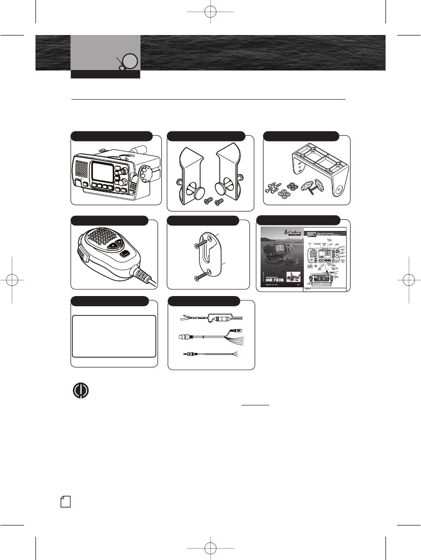
Included in this Package •
You should find all of the following items in the
package with your CobraMarine VHF radio:
NOTE
Cobra Accessory Harness CM 140-001 is an optional wire harness that is
used to interface the MR F80 radio with the Cobra MC 600C Series
chartplotters.
Installation and Start-Up
Transceiver Transceiver Flush Mount Kit
16/9
Microphone
Transceiver Surface Mount Kit
Operating Instruction Manual
WARNING
This equipment is designed to generate a digital
maritime distress and safety signal to facilitate
search and rescue. To be effective as a safety
device, this equipment must be used only within
communication range of a shore-based VHF
marine channel 70 distress and safety watch
system. The range of the signal may vary out
under normal conditions should be approximately
20 nautical miles.
Warning Sticker Power/Interface Cables
Mic Mounting Kit
F80 Installation.qxp:QXP-1058720374.qxp 12/29/06 10:02 AM Page 26
Nothing Comes Close to a Cobra®
Mounting and
Powering the Radio
27
Installation and Start-Up
Mounting and Powering the Radio •
Before using your CobraMarine VHF radio, it must be installed on your vessel.
Installing Your Radio
Choose a location for your radio where it will be conveniently accessible with the
following factors in mind:
The leads to the battery and the antenna should be as short as possible.
The antenna must be mounted at least 3 ft (0,9 m) from the transceiver.
The radio and all speakers need to be far enough from any magnetic
compass to avoid deviation due to the speaker magnet.
There needs to be free air flow around the heat-sink fins on the back
of the transceiver.
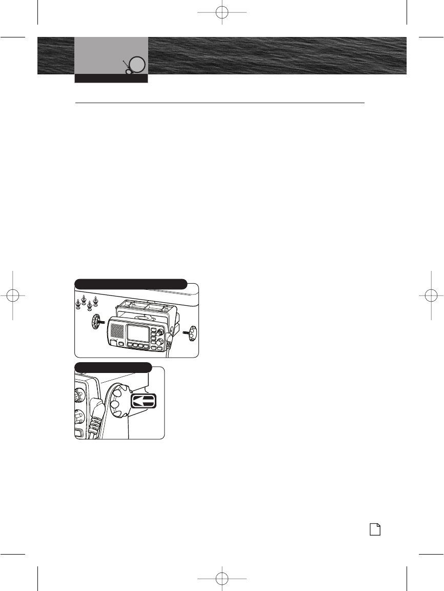
Surface Mount
A Surface Mounting kit is included with your CobraMarine VHF radio to allow its
installation on almost any flat horizontal surface.
To Mount the Transceiver
on Almost any Flat Surface:
1. Use the mounting bracket as a template
to drill holes for the mounting screws.
2. Attach the mounting bracket to the
chosen surface with the mounting
bracket screws and washers.
3. Attach the transceiver to the mounting
bracket with the Tilt Lock knobs.
4. Tilt the transceiver to a convenient
angle and tighten the Tilt Lock knobs.
Surface Mounting Kit
Tilt Lock Knobs
F80 Installation.qxp:QXP-1058720374.qxp 12/29/06 10:02 AM Page 27
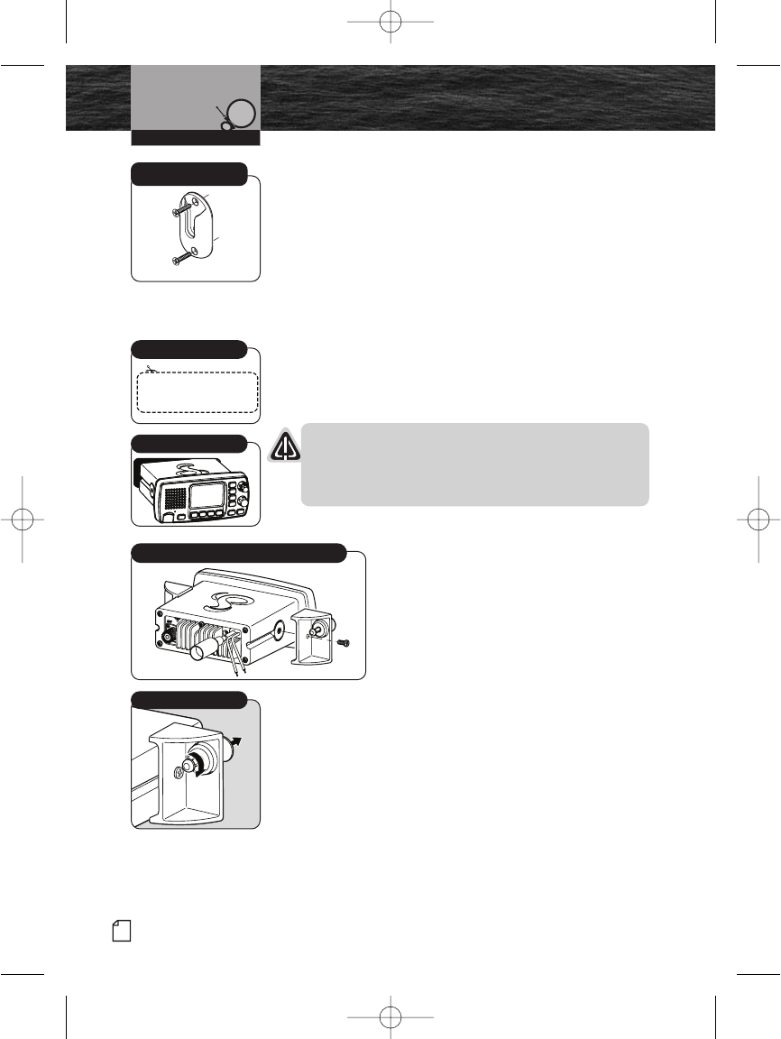
Microphone Bracket Mounting Kit
To Install The Microphone Bracket Mounting Kit:
Install the microphone bracket mounting kit on a
vertical surface near the transceiver using the
supplied stainless steel screws.
Flush Mount
A Flush Mount kit is included with your CobraMarine VHF
radio to allow its installation in almost any flat surface.
To Mount the Transceiver Flush in Almost any Flat Surface:
1. Use the supplied template (VHF Radio MRF80) to mark
and cut an opening in the flat surface. See page 80 for
template.
NOTICE
Before cutting, be sure the area behind the flat
surface is clear of any instruments, wires or structure
that might be damaged in the process.
2. Insert the transceiver into the opening.
3. Attach the mounting brackets to
the sides of the transceiver with
the adjusting screw flanges facing
the back of the flat surface.
4. Tighten the adjusting screws against
the back of the flat surface until the
flange on the front of the transceiver
is tight against the flat surface. Do not
over-tighten.
28 English
Installation and Start-Up
Mounting and
Powering the Radio
See final pages
for template.
Use Supplied Template
Insert Transceiver
Adjusting Screws
Attach Mounting Brackets
Microphone Bracket
Mounting Kit
F80 Installation.qxp:QXP-1058720374.qxp 12/29/06 10:02 AM Page 28
Nothing Comes Close to a Cobra®
Mounting and
Powering the Radio
29
Warning Sticker
FCC regulations require that the Warning Sticker
supplied with this radio be applied to a spot where
it is easily seen by the radio operator. Be sure the
location is clean and dry before applying the sticker.
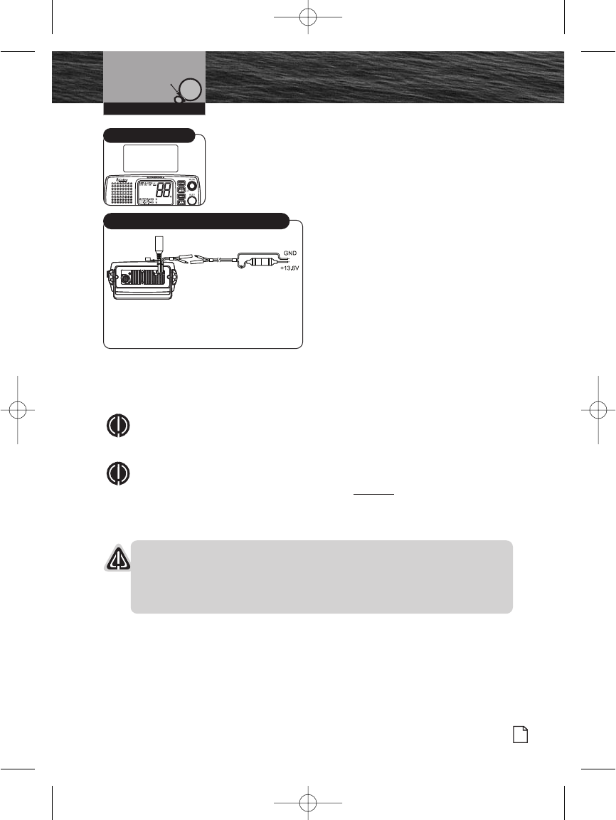
Electrical Power Connection
Electrical power is supplied to the
transceiver by two (2) bullet-type
connectors coming from a 13.8-volt DC
voltage source (12-volt nominal). The
positive lead must be attached to a fused
connector.
To Connect to a Power Source:
1. Attach the black (-) wire to a
negative (-) ground.
2. Attach the fused red power (+) wire
to the positive (+) side of the power
system.
NOTE
This radio will draw up to 8 amps when transmitting at full power.
NOTE
Cobra Accessory Harness CM 140-001 is an optional wire harness that is
used to interface the MR F80 radio with the Cobra MC 600C Series
chartplotters.
NOTICES
A reverse polarity connection will damage the radio.
When replacing the fuse in your transceiver, use only the size and type
originally provided.
Installation and Start-Up
WARNING
This equipment is designed to generate a digital
maritime distress and safety signal to facilitate
search and rescue. To be effective as a safety
device, this equipment must be used only within
communication range of a shore-based VHF
marine channel 70 distress and safety watch
system. The range of the signal may vary out
under normal conditions should be approximately
20 nautical miles.
Warning Sticker
Power Connection Cable
Red Cable
Positive (+)
Black Cable
Negative (-)
F80 Installation.qxp:QXP-1058720374.qxp 12/29/06 10:03 AM Page 29

30 English
Mounting and
Powering the Radio
Installation and Start-Up
NOTE
All wiring is best kept as short as possible. If the power leads must be
extended, use a high-quality, marine-grade cable sized for up to 10 amps
of current. To minimize voltage drop, choose a wire gauge as follows:
Length Wire Gauge
Up to 1.5m(4.9ft) 1.6 mils(#14)
Up to 3.0m(9.8 ft) 2.0 mils(#12)
Up to 5.0m(16.4 ft) 2.6 mils(#10)
Up to 6.0m(19.7 ft) 3.3 mils(#8)
F80 Installation.qxp:QXP-1058720374.qxp 12/29/06 10:03 AM Page 30
Nothing Comes Close to a Cobra®
Antenna Requirements
and Attachment
31
Installation and Start-Up
Antenna Requirements and Attachment •
Antenna Requirements
Your CobraMarine VHF radio requires an external marine antenna
to send signals into the air and to receive them. The radio is arranged
to use any of the popular marine VHF antennas, but it is up to you to
choose which antenna to use.
Since it represents the link between your radio and the outside world,
Cobra suggests you purchase the best quality antenna, coaxial cable
and connectors you can. This is best accomplished with the advice
and guidance of a knowledgeable dealer who can assess the variables
involved with your particular boat and preferences.
WARNING
Compliance with FCC requirements for Radio Frequency Exposure is
the responsibility of both the antenna installer and the radio operator.
Safe Maximum Permissible Exposure (MPE) Radius
To avoid health hazards from excessive exposure to RF energy, FCC OET
Bulletin 65 establishes an MPE radius of 10 ft (3 m) for the maximum power
of your radio with an antenna having a maximum power gain of 9 dBi.
This means that all persons must be at least 10 ft (3 m) away from the
antenna when the radio is transmitting.
Installation Requirements
An omnidirectional antenna with a gain not greater than 9 dBi must
be mounted at least 16.4 ft (5 m) above the highest deck where people
may be during radio transmissions, measured vertically from the lowest
point of the antenna. This provides the minimum separation distance
to comply with RF exposure requirements and is based on the MPE
radius of 10 ft (3 m) plus the 6.6 ft (2 m) height of an adult.
For vessels without structure to mount the antenna as described in A,
it must be mounted as follows AND all persons must be outside the
10 ft (3 m) MPE radius during radio transmissions. The antenna must
be mounted so that its lowest point is at least 3.3 ft (1 m) vertically above
the heads of all persons during radio transmissions.
F80 Installation.qxp:QXP-1058720374.qxp 12/29/06 10:03 AM Page 31
32 English
Antenna Requirements
and Attachment
WARNING
Do not transmit when anyone is within the MPE radius of the antenna unless
that person or persons are shielded from the antenna by a grounded metallic
barrier. This is especially important on vessels with antennas mounted as
described in B where no one may be within 9 ft (2,8 m) horizontally from the
base of the antenna during transmissions.
FAILURE TO OBSERVE THE ABOVE LIMITS MAY EXPOSE THOSE WITHIN
THE MPE RADIUS TO RF ENERGY ABSORPTION IN EXCESS OF THE FCC
MAXIMUM PERMISSIBLE EXPOSURE. IT IS THE RADIO OPERATOR’S
RESPONSIBILITY TO ENSURE THAT MPE LIMITS ARE HEEDED AND THAT
NO ONE IS WITHIN THE MPE RADIUS DURING TRANSMISSIONS.
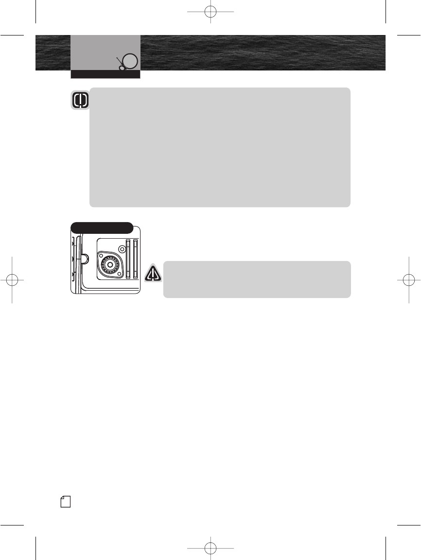
Antenna Lead Attachment
Once the antenna is installed, the Coaxial Cable Lead can
be attached to the coaxial cable socket at the back of the
transceiver.
NOTICE
Attempting to transmit without an antenna attached
will damage your CobraMarine VHF radio.
Installation and Start-Up
Coaxial Cable Socket
F80 Installation.qxp:QXP-1058720374.qxp 12/29/06 10:03 AM Page 32

Nothing Comes Close to a Cobra®
External Devices
and Connections
33
External Devices and Connections •
Your CobraMarine VHF radio is set up to connect auxiliary devices for navigation,
convenience and added versatility. As is the case with the antenna, choosing these
devices is best done with the advice and guidance of a knowledgeable dealer.
Standard connectors are provided on the front and back of the transceiver.
NMEA Communication Cable
Your CobraMarine Radio is set up with an NMEA communication port that allows the
radio to communicate with other electronic equipment such as a GPS Chartplotter,
Depth Sounder, Auto Pilot, DSC VHF Radio, Radar and Personal Computer with the
ability to display information. This capability allows for the operator to do Position
Polling and Position Requests directly from the radio. The NMEA input and output
leads are directed through the NMEA communication port.
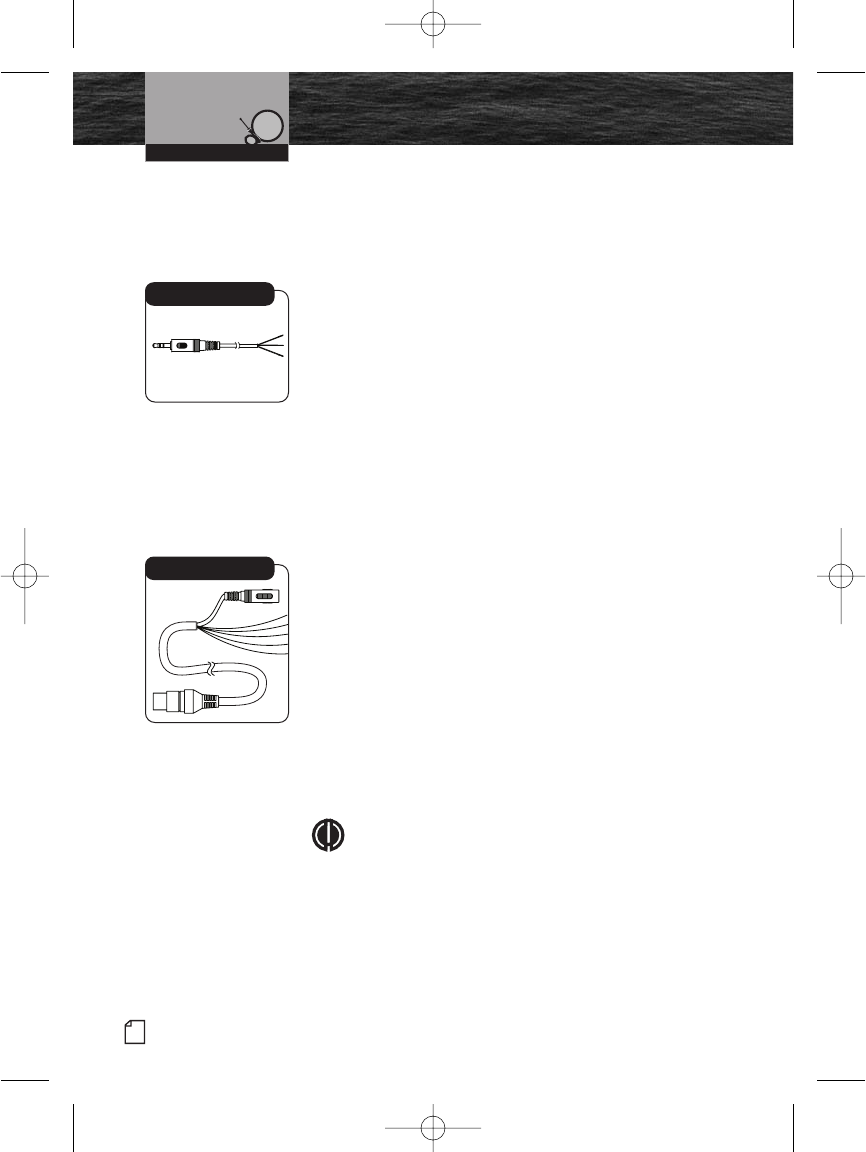
External Speaker (Not Included)
An External Speaker can provide greater volume to hear messages than the speaker
in the transceiver.
To Install an External Speaker:
1. Connect the speaker positive (+) wire to the orange wire coming out of the
standard speaker/PA wire harness.
2. Connect the speaker negative (-) wire to the black/white wire coming out of the
standard speaker/PA wire harness.
Installation and Start-Up
NMEA Cable
F80 Installation.qxp:QXP-1058720374.qxp 12/29/06 10:03 AM Page 33
34 English
External Devices
and Connections
Public Address Speaker (Not Included)
At times, it may be handy to address other boats or give
instructions to line handlers on the dock. Your CobraMarine
VHF radio can be switched to operate in the Public Address
mode through an attached PA speaker.
To Install a Public Address Speaker:
1. Connect the PA speaker positive (+) wire to the rose red
wire coming out of the standard speaker/PA wire harness.
2. Connect the PA speaker negative (-) wire to the
black/white wire coming out of the standard speaker/PA
wire harness.
Global Positioning System (GPS) Device
(Not Included)
Cobra Electronics strongly recommends that you obtain and
connect a GPS device to your CobraMarine VHF radio. By
having a GPS connected, your position will
be continuously indicated on the LCD and, most importantly,
it will be included automatically in any DSC distress
message you may need to send. That will
take the “search” out of “search and rescue.”
To Install a GPS Device:
1. Install the GPS device in a convenient location according
to its manufacturer’s directions.
2. Bond the NMEA out negative (-) wire of your GPS to the
NMEA in negative (-) wire (green) of the MR F80
NMEA/IO interface cable.
3. Bond the NMEA out positive (+) wire of your GPS to the
NMEA in positive (+) wire (white) of the MR F80
NMEA/IO interface cable.
NOTE
When bonding the wires, make sure connections are
secure and properly insulated to prevent electrical
arching.
4. Connect the new combination cable to the GPS device
and to the back of the transceiver.
Installation And Start-Up
Speaker/PA Cable
NMEA/IO Cable
F80 Installation.qxp:QXP-1058720374.qxp 12/29/06 10:03 AM Page 34
Nothing comes close to a Cobra®
External Devices
and Connections
NOTE
Satellite acquisition time is dependent on the GPS device.
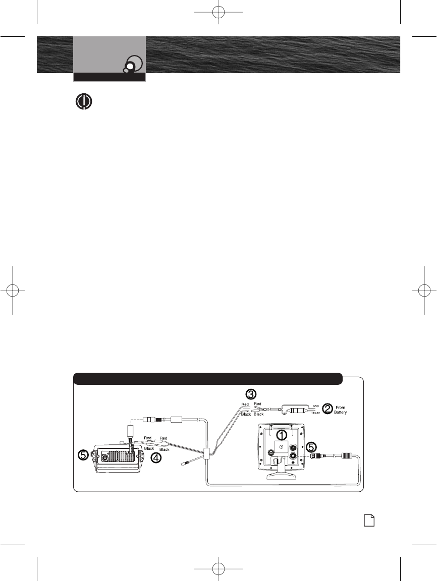
CobraMarine Chartplotter MC 600C Series
Your CobraMarine VHF radio is set up to connect directly to your chartplotter with a
custom accessory cable that eases the installation.
The chartplotter uses a state-of-the-art electronic chart system, designed as a
custom navigation aid. All calculations and information necessary for the navigation
are performed and displayed on the chartplotter quickly and accurately providing all
of the capabilities of a conventional GPS, but with the added benefit of a powerful
electronic chart display.
Wiring the chartplotter to the transceiver is made easy with a custom-made optional
Accessory Cable harness P/N CM 140-001. This cable has a molded 8-pin connector
that plugs directly into the appropriate connectors on the MR F80 and the MC 600C
Series.
To Install the Chartplotter:
1. Install the chartplotter in a convenient location according to the chartplotter
owner’s manual.
2. Complete the Electrical Power Connection to the power cable as detailed on
page 29.
3. Connect the red and black bullet connectors on the power cable supplied with the
MR F80 to the mating connectors on the CM 140-001 cable.
4. Connect the red and black bullet connectors on the back of the radio to the
mating connectors on the CM 140-001 cable.
5. Plug in the 8 pin connectors to the MR F80 and MC 600C.
35
Operating Your Radio
MR F80 to Chartplotter Connection
F80 Installation.qxp:QXP-1058720374.qxp 12/29/06 10:03 AM Page 35
36 English
Getting Started
Getting Started •
Refer to the foldout at the front of this manual to identify the various
controls and indicators on your radio.
Throughout this manual you will be instructed to press, or to press and hold buttons
on the transceiver or on the microphone/speaker. Press means a momentary press,
then release; press and hold means to hold the button down.
Tones and Alarms
When your CobraMarine VHF radio is On, you can expect to hear the following tones
and alarms. The volume of these sounds is controlled by the circuitry in
the radio and is not affected by the volume set with the On-Off Power/Volume
knob or Volume Up/Down buttons.
Confirmation Tone
A single, high-pitched beep confirms all button presses except the Talk button.
It can be turned On or Off. See setup routines on page 41.
Error Tone
Three (3) medium-pitch tones indicate an invalid button press (error).
DSC Distress Alarm
High—low—high—low—high. Pause, then repeat. The volume of this alarm will
increase after 10 seconds. Press any button to turn it Off.
NOTE
This alarm sounds only for DSC distress calls on Channel 70.
It does not sound for voice calls on Channel 16 — you still
must listen for those.
Distress Acknowledgement Alarm
High—low. Long pause, then repeat. Press any button to turn it Off.
DSC Routine Call Alarm
High—pause—high—pause—high. Long pause, then repeat. Press any button to
turn it Off.
DSC Geographical Alarm
Loud, continuous, medium-pitched, high-low tones (warble) — sounds
when a geographical call is received. Press any button to turn it Off.
Operating Your Radio
F80 Installation.qxp:QXP-1058720374.qxp 12/29/06 10:03 AM Page 36
Nothing Comes Close to a Cobra®
Getting Started
37
DSC Position Request Alarm
Medium-loud, continuous, low-pitched series of closely
spaced, four (4) beeps [three (3) short – one (1) long]
groups — sounds when a POSITION REQUEST call is
received. Press any button to turn it Off.
DSC Individual Alarm
Medium-loud, continuous, medium-pitched, three (3) beep
groups — sounds when an Individual call is received. Press
any button to turn it Off.
Weather Alarm
Medium-loud, continuous, medium-pitched series of one-
half second beeps spaced one-half second apart — sounds
when weather alert is turned On and NOAA sends a 1050 Hz
weather alert tone on the selected weather channel. Press
any button to turn it Off.
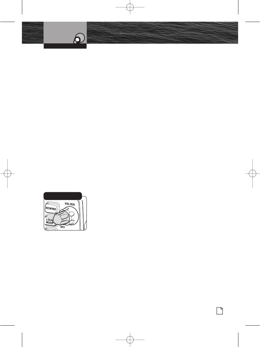
Power On-Off – Volume/Squelch
On-Off
Transceiver power can be turned On or Off by using the
On/Off — Volume rotary concentric knob located at the
upper right-hand side of the radio.
Volume
Volume is controlled by turning the On/Off Volume rotary
concentric knob. The radio speaker is located on the left side
of the display.
To increase the volume, turn the Rotary knob clockwise.
To decrease the volume, turn the Rotary knob
counterclockwise.
Operating Your Radio
On/Off Power/
Volume Knob
F80 Installation.qxp:QXP-1058720374.qxp 12/29/06 10:03 AM Page 37
38 English
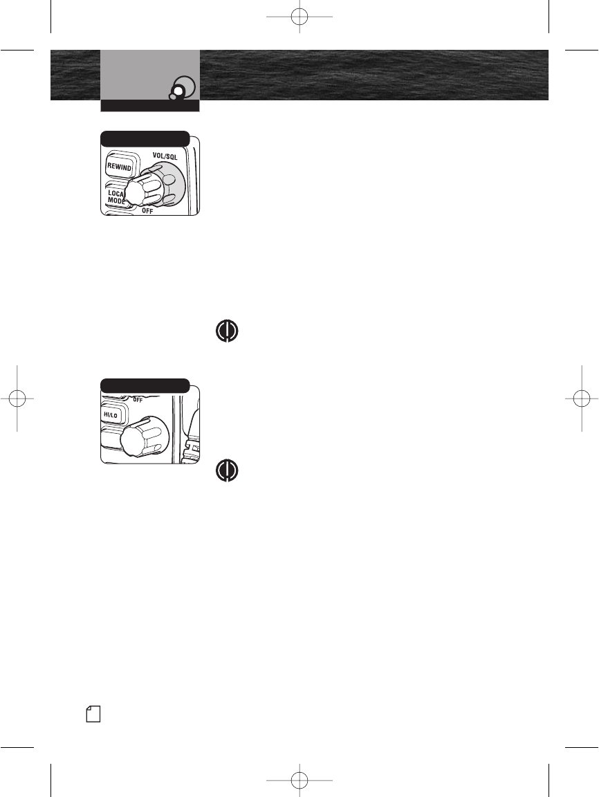
Squelch
Squelch control is controlled by turning the inner (back)
rotary concentric knob located directly behind the On/Off –
Volume knob. With the power On, turn the knob
counterclockwise till you hear a hissing sound, then turn the
knob clockwise till the hissing stops. This will establish a
“Baseline” squelch.
By turning the knob further in a clockwise direction, you will
filter weak and medium-strength signals. By turning the
knob further in a counterclockwise direction from your
baseline setting, you will receive weaker signals.
Squelch control filters weak signals and radio frequency
(RF) noise so that you will clearly hear the signals you want.
NOTE
If the Squelch is set so that you can hear a continuous
hissing sound, the Memory Scan and Tri-Watch
functions will be blocked.
Channel Select Using Radio Knob
Allows for the manual selection of all the VHF marine
channels that have been established for use in the U.S.A.,
Internationally and in Canada.
NOTE
This knob will also allow scrolling in many of the
setup and advanced operation menus.
When the Channel Select knob on the radio is turned in a
clockwise rotation, higher numbered VHF marine channels
can be accessed. When the Channel Select knob on the
radio is turned in a counterclockwise direction, lower
numbered VHF marine channels can be accessed.
Channel Select Using Microphone
By pressing microphone Channel Up button, higher
numbered VHF marine channels can be accessed. By
pressing the microphone Channel Down button, lower
numbered VHF marine channels can be accessed.
Getting Started
Operating Your Radio
Squelch Knob
SELECT
MEM
Channel Select Knob
F80 Installation.qxp:QXP-1058720374.qxp 12/29/06 10:03 AM Page 38
Nothing Comes Close to a Cobra®39
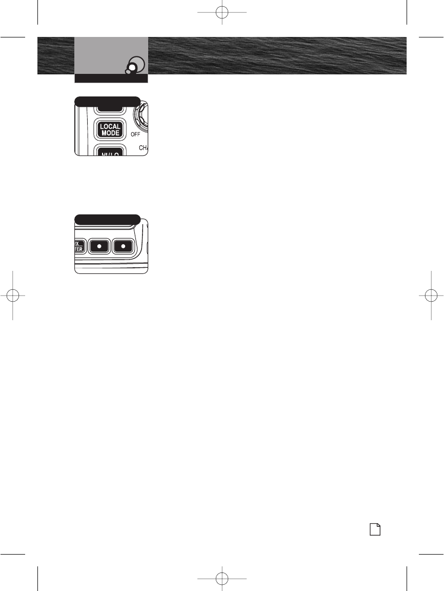
Local Mode Button
The radio features a Local Mode button that decreases radio
sensitivity when operating inside populated areas.
When the Local Mode button is On, the power of an
inbound receive (Rx) signal is reduced without distorting
the waveform. Reducing an inbound signal power
prevents “noise interference” from random RF Noise in
populated marinas, cities and commercial areas. When
the Local Mode button is On, the “Local On” icon
displays.
When the Local Mode button is Off, the radio receives a
full signal with an extended operational range.
Channel Preset (Function) Buttons
Use the Channel Preset buttons for direct access to favorite
channels in the Standby mode and as selection keys in the
Setup mode.
When a Channel Preset button is pressed and released,
the radio goes directly to the assigned preset channel. If
no preset channels are assigned, three (3) error tones
sound. After the button is released, the radio returns to
the Standby mode.
When a Channel Preset button is pressed and held for
more than two (2) seconds, the working channel will be
assigned to the button.
Getting Started
Operating Your Radio
Local Mode Button
Channel Preset Buttons
F80 Installation.qxp:QXP-1058720374.qxp 12/29/06 10:03 AM Page 39
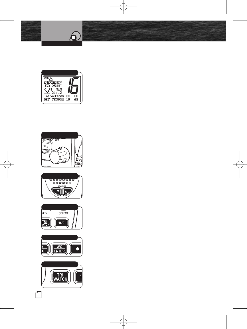
40 English
Getting Started
Introduction
Standby and Receive
Standby mode is the usual mode for the radio whenever it is
turned On.
From Standby Mode, You Can:
Change your radio’s settings using setup routines.
Receive messages on the current channel as well as DSC
messages.
Receive NOAA alerts if Weather Alert mode is turned On.
Switch to Transmit mode using the Talk button.
While the radio is in Standby mode, the Receive mode is
entered whenever a strong enough signal to break squelch
is sent to the radio. You will hear the message through
whichever speakers are connected to the radio.
To Change the Channel You Are Listening to, You Can
Choose One of the Following:
1. Turn the Channel Select knob clockwise for higher VHF
channel. Turn the Channel Select knob counterclockwise
for lower VHF channel.
2. Press Channel Up/Down buttons on microphone to go to
the next higher or lower VHF channel. For rapid advance,
press and hold the Channel Up/Down button.
3. Press the Channel 16/9 button. This will take you to
Channel 16 with one (1) press and to Channel 9 with a
second press. Additional presses will toggle between
Channels 16, 9 and original channel.
4. Press the Weather/Enter button. This will allow you
access to the weather channels. Turning the Channel
Select knob or pressing the Channel button on the
microphone allows you to change weather channels.
5. Press the Tri-Watch button to monitor three (3) Channels
16, 9 and one user selectable channel.
Standby Mode
SELECT
MEM
Channel Select Knob
Mic Channel Buttons
Channel 16/9 Button
Tri-Watch Button
WX/Enter Button
F80 Installation.qxp:QXP-1058720374.qxp 12/29/06 10:03 AM Page 40
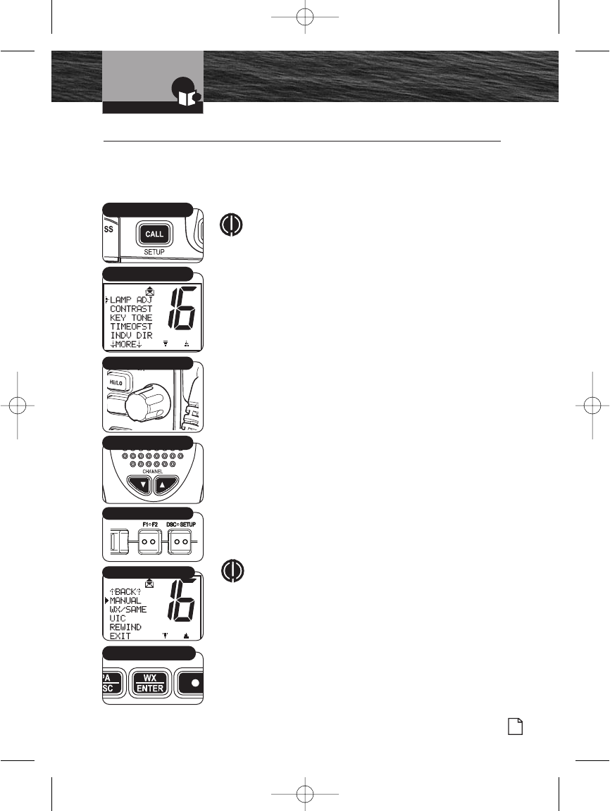
Introduction
Nothing comes close to a Cobra®
Setup Mode Programming
41
Setup Mode Programming •
Setup Menu
Use the Setup menu in the CobraMarine VHF radio to turn On
and Off many features, to adjust feature preferences and enter
a user MMSI number.
NOTE
Basic Setup menu programming is described in this
section. For Setup menu programming that applies to
a specific function refer to that section in this manual.
For example, MMSI information is in the DSC portion
of the manual.
Basic Scrolling in the Setup Menus:
The Channel Select knob on the radio can be used to scroll
through different menus and confirm selections chosen by the
user. Alternately, scrolling selection functions can be made
from the microphone by using the Channel Up/Down or
Function (F1/F2) button.
To Enter the Setup Menu:
Press and hold the Call/Setup button. The Setup menu
appears on the LCD. Scroll up or down through the Setup
menu until the desired function to program is positioned to
the right of the selection arrow.
To Exit any Setup Menu:
Scroll down to “EXIT” at the bottom of the menu. With the
arrow pointing toward “EXIT,” press the Enter button to return
the radio to the Standby mode.
NOTE
The ESC button on the radio (and the Function F1/F2
button on the microphone) can also be used
universally to return to the Standby mode.
Call/Setup Button
Mic Function Buttons
Mic Channel Buttons
Exit
Enter Button
Setup Menu
SELECT
MEM
Channel Knob
F80 Installation.qxp:QXP-1058720374.qxp 12/29/06 10:03 AM Page 41
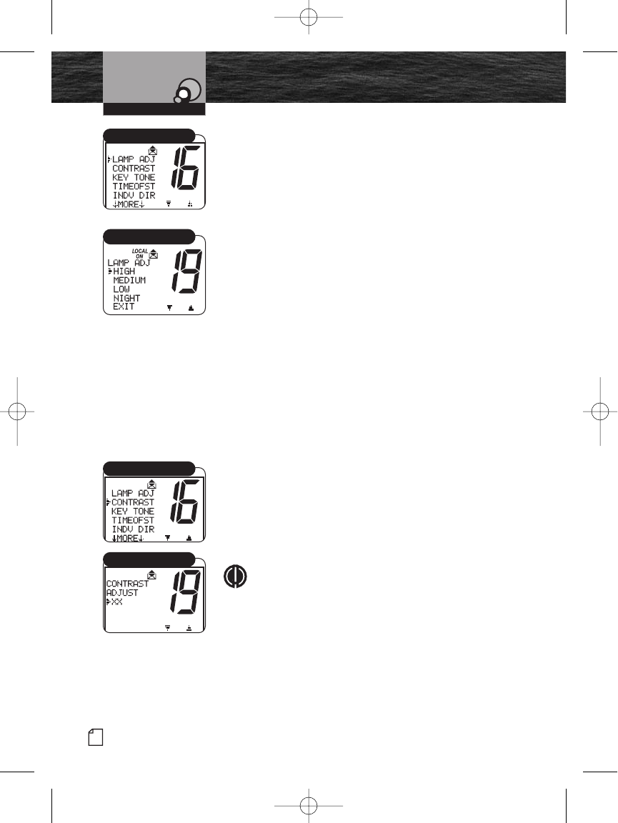
42 English
Setup Mode Programming
LCD Display Lamp Adjust
The LCD display has a backlight lamp to make it visible in
the dark. The lamp can be adjusted for brightness or turned
off. Make all lamp adjustments in the LAMP ADJ menu.
The lamp will operate at the HIGH level until adjusted to
HIGH, MEDIUM, LOW, NIGHT or OFF.
To Adjust the LCD Display Lamp Level:
1. Enter the Setup menu and scroll to the LAMP ADJ menu.
2. Press the Enter button and observe the current backlight
lamp setting — HIGH, MEDIUM, LOW, NIGHT or EXIT.
3. Move the selection arrow to the required setting.
4. Press the Enter button to select the backlight lamp
setting.
5. When the changes are complete, exit the LAMP ADJ
menu and return to the Setup menu.
When the backlight is turned On, the lamp remains lit
anytime the radio is On.
LCD Contrast
Adjust the LCD display contrast for easy reading in different
lighting. Make all contrast adjustments in the CONTRAST menu.
To Change the Contrast:
1. Enter the Setup menu and scroll to the CONTRAST menu.
2. Press the Enter button and observe the current contrast
setting — a number between 1 and 16.
3. Turn the Channel knob to increase or decrease the
contrast setting.
NOTE
Contrast is lighter at lower number settings and
darker at higher number settings.
4. Press the Enter button to select the contrast setting.
5. When the changes are complete, exit the CONTRAST
menu and return to the Setup menu.
Operating Your Radio
Lamp Adjustment
High/Medium/Low/Exit
Contrast
Contrast Setting
8187-F80-Operation-8_MMB:F75-Operation-8 12/29/06 9:02 AM Page 42
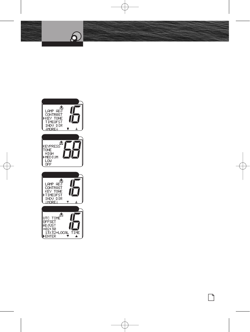
Nothing Comes Close to a Cobra®
Setup Mode Programming
43
Key Tone
The confirmation key tone sounds when the CobraMarine
VHF radio is turned On and confirms all button presses
except for the Talk button. The confirmation key tone is
easily turned On or Off. Make all confirmation key tone
adjustments in the KEY TONE menu.
To Turn the Confirmation Key Tone On or Off:
1. Enter the Setup menu and scroll to the KEY TONE menu.
2. Press the Enter button and observe the current
confirmation key tone setting — High, Medium, Low or
Off.
3. Select your desired level.
4. Press the Enter button to select the key tone setting.
5. When the changes are complete, exit the KEY TONE menu
and return to the Setup menu.
Time Offset
All VHF, DSC, and GPS activities use a 24-hour clock and
Coordinated Universal Time (UTC) formerly known as
Greenwich Mean Time (GMT). Time Offset uses a connected
GPS to gather time inputs. To convert time inputs to local
time, enter the hour offset of the local time zone from the
Time Zone Chart on page 25.
To Change the Time Offset:
1. Enter the Setup menu and scroll to TIMEOFST menu.
2. Press the Enter button and observe the current time
offset setting.
3. Move the selection arrow to the setting for your local
time zone.
4. Press the Enter button to select the local time zone
setting.
5. When the changes are complete, exit the TIMEOFST
menu and return to the Setup menu.
Operating Your Radio
Key Tone
On/Off
Set Time
Time Offset
8187-F80-Operation-8_MMB:F75-Operation-8 12/29/06 9:02 AM Page 43
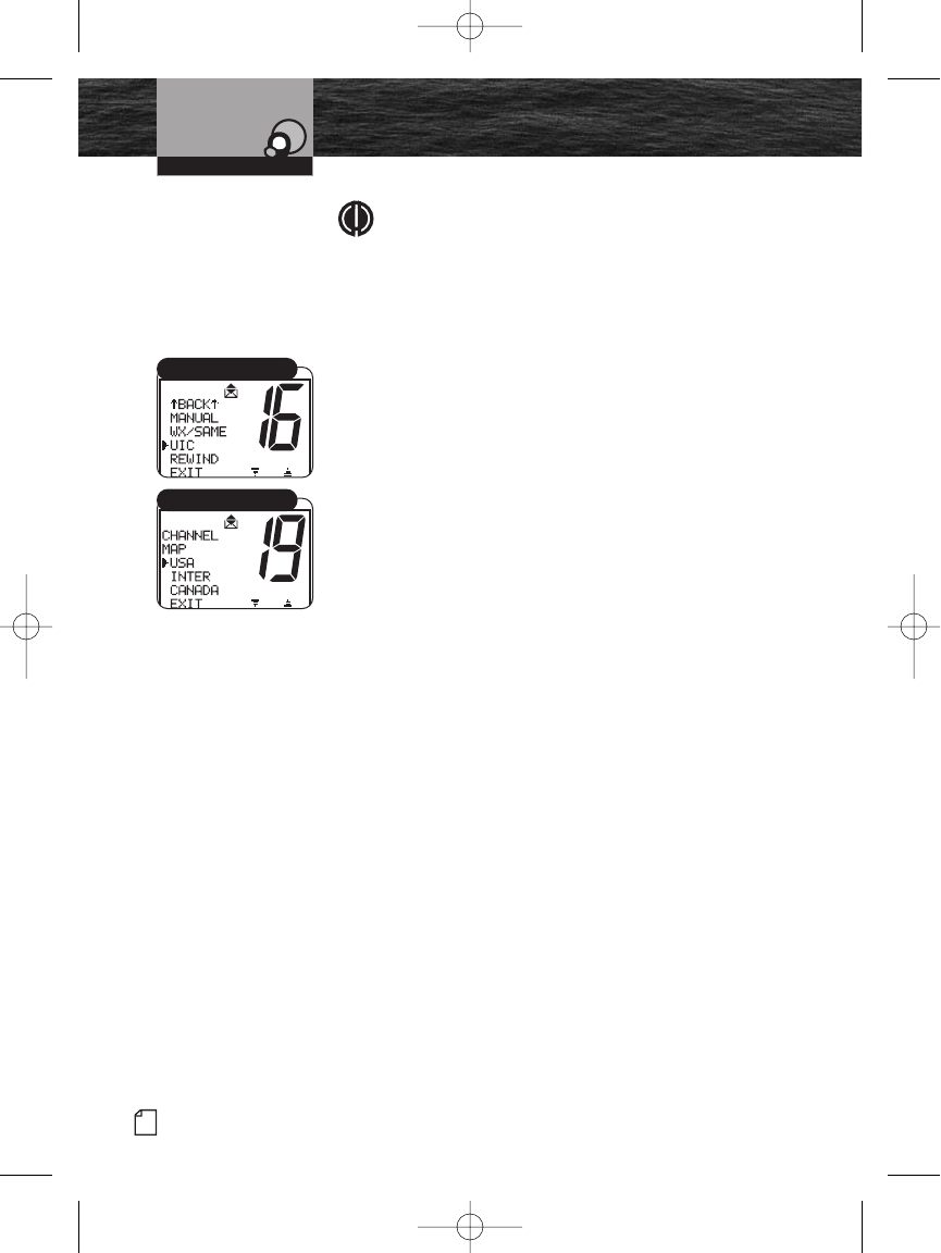
44 English
Setup Mode Programming
NOTE
When the time offset is at zero (0), the LCD shows the
time as UTC. When a time zone hour offset is entered,
the LCD shows the local time. All DSC messages are
based on UTC.
The radio will also show the local time as the
adjustment is being made.
U.S.A./International/Canada (UIC) Channel Maps
There are three (3) sets of VHF Channel Maps for marine
use in the U.S.A., Canada and the rest of the world
(International). Most of the channels are the same for all
three (3) maps, but there are differences (see tables on
pages 16-23). The radio is built with all three (3) channel
maps included and operates correctly in any selected area.
To Set the Radio for the Area Used:
1. Enter the Setup menu and scroll to the UIC menu.
2. Press the Enter button and observe the current channel
map setting.
3. Move the selection arrow to select the desired channel.
4. Press the Enter button to select the channel map setting.
5. When the changes are complete, exit the UIC menu and
return to the Setup menu.
Operating Your Radio
UIC Channel Map
UIC Select
8187-F80-Operation-8_MMB:F75-Operation-8 12/29/06 9:03 AM Page 44
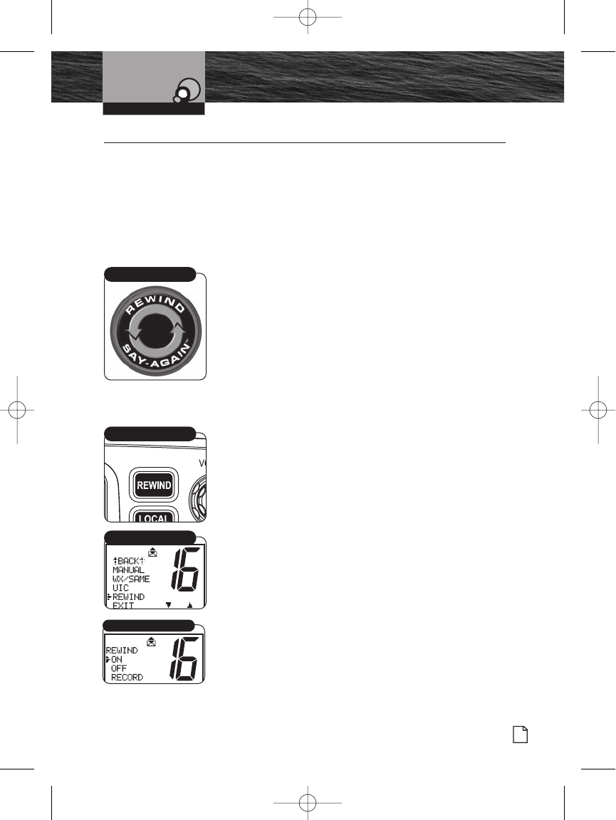
Nothing Comes Close to a Cobra®
Special Features
45
Special Features •
Rewind-Say-Again™ Feature
The MR F80 radio has a Cobra exclusive playback feature,
Rewind-Say-Again™. This feature allows you to replay the
last 20 seconds of an incoming audio transmission. It also
allows you to record call details including position
coordinates, call signs, registration numbers and store details
that will help authorities locate a distressed vessel.
Example 1:
When engine noise, music or conversation creates too much
noise to hear an inbound message clearly, press the Rewind-
Say-Again™ button to hear the message a second time. This
feature eliminates asking the sender to repeat the message.
Example 2:
When listening to an urgent distress of an excited caller with
confusing background noise, press the Rewind-Say-Again™
button to hear the message a second time and get lifesaving
information.
Operation of Rewind-Say-Again™
1. Press the Rewind button after the last inbound audio
transmission.
2. The radio automatically replays the last 20 seconds of the
previous audio transmission.
3. Respond to the caller normally, after the message is
replayed.
Setup and Advanced Operation of Rewind-Say-Again™
Change the Record Setting
1. Enter the Setup menu and scroll to the REWIND menu.
You can also enter the REWIND mode by pressing and
holding the REWIND button.
2. Press the Enter button and observe the current rewind
setting — ON or OFF.
3. Select your choice: ON or OFF and press Enter. Choose
ON if you want the MRF80 to record received
transmissions. Choose OFF if you want to turn off the
recording feature.
Operating Your Radio
Rewind-Say-Again™
Rewind Button
Rewind Menu
Rewind On/Off/Record
8187-F80-Operation-8_MMB:F75-Operation-8 12/29/06 9:03 AM Page 45
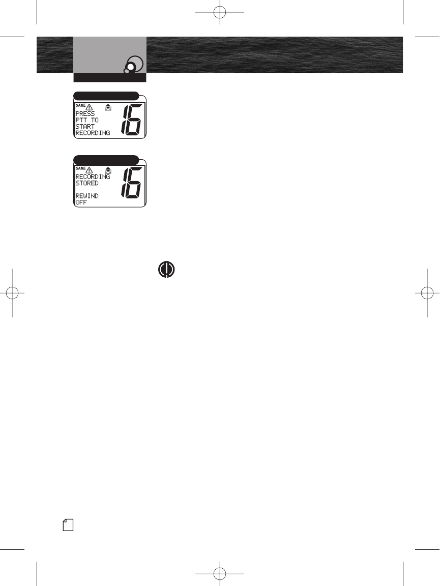
46 English
Special Features
Make Your Own Recording
The recording feature may also be used to store other
important information like fuel consumption, water
conditions, fishing notes (such as thermal cline depths, type
of bait, etc.) and other “On Water” observations.
1. Follow the steps above to get into REWIND mode setup.
2. Select the RECORD function. Press ENTER to start the
recording mode.
3. Press the Push to Talk (PTT) button on the microphone
to begin your recording. A 20-second countdown
displays showing how much time remains for recording.
At the end of 20 seconds, a beep sounds indicating that
the recording time is completed.
4. Playback recorded message or select OFF to exit this mode
and keep the recording in memory.
NOTE
The REWIND feature can also be used to permanently
store an incoming message. This could be useful if
you are not able to copy information while underway
such as coordinates, directions and other
complicated information. Once the incoming
transmission (up to 20 seconds) is complete, Follow
the instructions to turn the REWIND feature off. The
last incoming transmission will be recorded to the
unit’s memory.
Operating Your Radio
PTT Menu
Recording Stored Menu
8187-F80-Operation-8_MMB:F75-Operation-8 12/29/06 9:03 AM Page 46
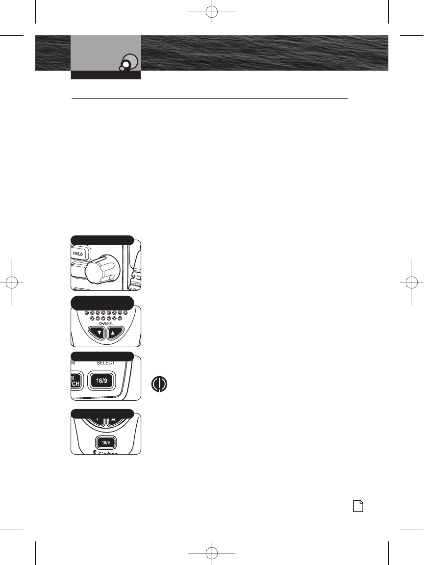
Introduction
Nothing Comes Close to a Cobra®
Product Features
47
Voice Transmission
Operating Your Radio
Voice Transmission •
Use the Transmit (TX) mode to communicate with safety
services, other vessels and shore stations. When using this
capability, follow appropriate procedures and observe the
expected courtesies.
Before pressing the Talk button to transmit a message, select
the appropriate channel and transmit power output.
Channels
Voice messages may be transmitted on most VHF channels.
Refer to the VHF marine channel assignments on pages 14-23
to select a channel based on the type of message being
transmitted.
Choose One of the Following Options to Change the
Channel:
Turn the Channel knob or press the microphone Channel
Up/Down buttons. This moves the channel to the next
higher or lower VHF channel. (When on Channel 88A, the
next higher channel is Channel 1 and vice versa.) For
rapid advance, press and hold the microphone Channel
Up/Down buttons. (The confirmation key tone sounds for
each button press, but not during rapid advance.)
Press the Channel 16/9 button on the radio or the
microphone. This selects Channel 16 with one press and
Channel 9 with a second press. Additional presses will
toggle between Channel 16 and Channel 9. Press and
hold the Channel 16/9 button to return to Standby mode.
NOTE
The radio will automatically select high power on
channel 16 if you use the Channel 16/9 button to
select this channel. Select 16 manually or save it as
a preset if you would like to routinely use channel
16 on low power mode.
SELECT
MEM
Channel Knob
Channel 16/9 Button
Microphone
Up/Down Buttons
Microphone 16/9 Button
8187-F80-Operation-8_MMB:F75-Operation-8 12/29/06 9:03 AM Page 47
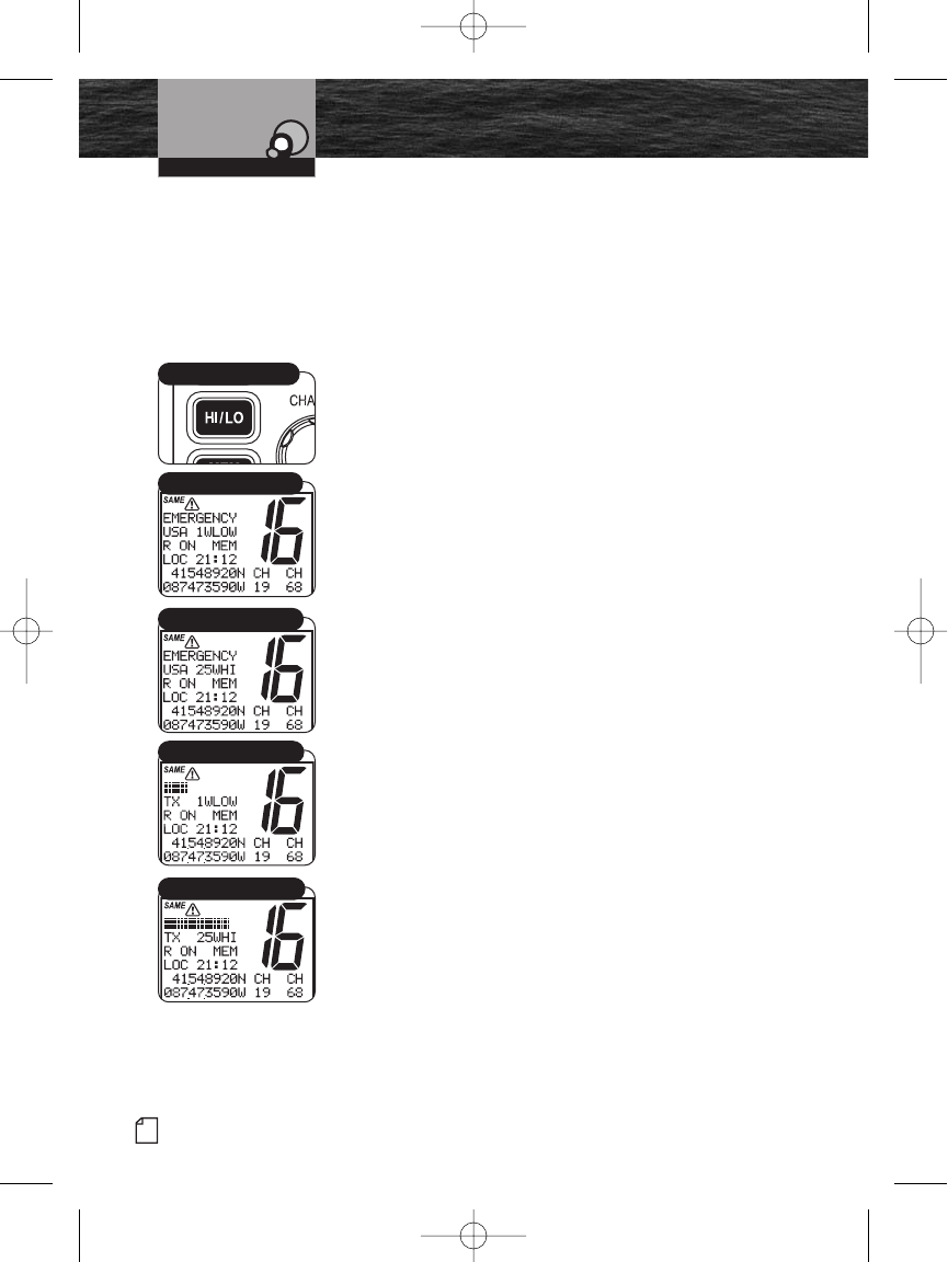
48 English
Voice Transmission
Transmit Power Output
The radio transmits selectively at 1 or 25 watts of power.
Cobra suggests maintaining the low power setting for short-
range communications to avoid overpowering nearby stations
with the signal. Use the high power setting for long-range
communications or when no response is received from a
signal sent at 1 watt.
To Toggle Between the High and Low Power Modes:
Press the HI/LO Power button.
The LCD displays which mode is selected.
Some channels are restricted to be used at a maximum of 1
watt. The radio automatically sets the power to Low Power
mode when a restricted channel is selected.
While using the U.S.A. channel map, if, in an emergency, it is
necessary to increase the output power on Channel 13 and
Channel 67 for the signal to be heard, override the Low
Power mode by pressing and holding the HI/LO Power
button.
Transmit a Message
To Transmit a Message:
1. Check to see that the radio is set to a proper channel for
the type of message being sent.
2. Toggle to the low power setting by pressing the HI/LO
Power button.
3. With the microphone about 2 in. (51 mm) from your
mouth, press and hold the Talk button and speak into the
microphone. TX (Transmit) displays on the LCD display.
4. Release the Talk button when finished speaking. To hear
a response, the Talk button must be released.
Operating Your Radio
HI/LO Power Button
Standby High Power Mode
Standby Low Power Mode
Transmit High Power Mode
Transmit Low Power Mode
8187-F80-Operation-8_MMB:F75-Operation-8 12/29/06 9:03 AM Page 48
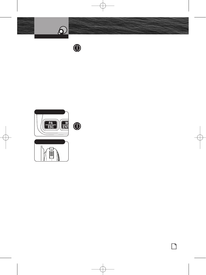
Introduction
Nothing Comes Close to a Cobra®
Product Features
49
Voice Transmission
NOTE
If the Talk button is held down for five (5) minutes,
the radio automatically ceases transmitting to prevent
unwanted signal generation and a three (3)-beep error
tone sounds. As soon as the Talk button is released, it
can be pressed again to resume transmission.
Public Address
Use the Public Address (PA) mode of voice transmission to
communicate to other nearby vessels or people. This feature
requires a mounted and connected optional PA speaker.
To Broadcast on the PA Speaker:
1. Press the PA/ESC button on the front of the transceiver.
2. Press the Talk button on the microphone and speak into
the microphone.
NOTE
While in the PA mode:
When the Talk button is pressed; the output is
directed to the PA speaker and not transmitted as a
radio signal through the antenna.
Received radio messages are directed to the PA
speaker unless the Talk button is pressed.
3. To turn off PA, press PA/ESC button on the front of the
radio again or press the Function F1/F2 button on the
microphone to ESC.
Operating Your Radio
Talk Button
PA/ESC Button
8187-F80-Operation-8_MMB:F75-Operation-8 12/29/06 9:03 AM Page 49
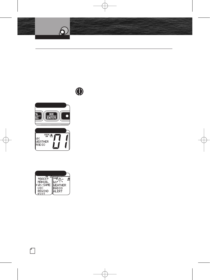
50 English
NOAA All Hazards/Weather
Radio and Alert, w/SAME
NOAA All Hazards/Weather Radio and Alert, w/SAME •
NOAA broadcasts weather information as described in the
NOAA Weather Channels section on page 25 of this manual.
Listen to one of these receive-only channels at any time. The
transceiver also incorporates “Specific Area Message
Encoding (SAME)” and “Emergency Alert System Codes” sent
by NOAA. These codes provide the type of alert, and are listed
on page 51.
NOTE
Usually only one (1) or two (2) of the weather
channels operate in a location. Select the channel
with the strongest signal in your location. The radio
scans this channel for the weather alert signal.
To Listen to the Weather Channels:
1. From Standby mode, press the WX/ENTER button. The
unit enters the Weather mode and displays on the LCD.
2. Turn the Channel knob or press the Channel Up/Down
buttons on the microphone to change the weather
channels.
3. To exit the Weather mode and return to Standby mode,
press the WX/ENTER button again.
Weather Alert Setup
The Weather Alert mode must be turned On to receive the
Weather Alert condition signal described in the NOAA weather
channels section on page 25.
To Turn Weather Alert On:
1. Enter the Setup menu and scroll to WX/SAME (weather
alert) menu.
2. Press the Enter button and observe the current weather
alert setting — ON, OFF or EXIT.
3. Move the selection arrow to select the desired weather
alert setting.
4. Press the Enter button to select the weather alert setting.
5. When the changes are complete, exit the WX/SAME menu
and return to the Setup menu.
Operating Your Radio
WX/Enter Button
Weather Mode
WX/SAME Menus
8187-F80-Operation-8_MMB:F75-Operation-8 12/29/06 9:03 AM Page 50
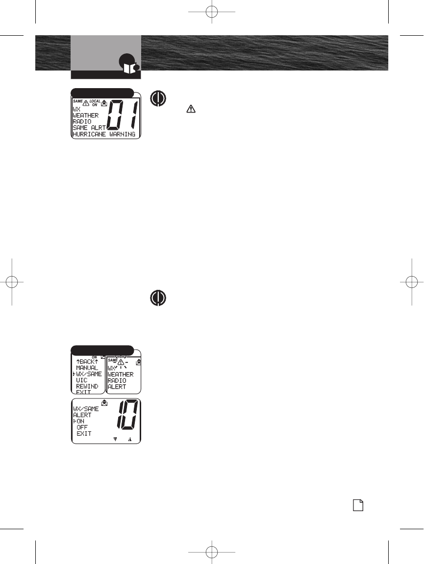
Introduction
Nothing Comes Close to a Cobra®
NOAA All Hazards/Weather
Radio and Alert, w/SAME
51
NOTE
The symbol will appear on the top of the display
when the weather alert is turned On.
Specific Area Message Encoding (SAME)
The SAME weather alert allows listeners and EAS
(Emergency Alert System) participants to filter the National
Weather Radio (NWR) broadcast of warnings and emergency
alerts to receive only messages and information for your
selected local geographic area.
The Weather Alert must be turned On for the SAME alert
code to be set. The SAME alert requires that a specific six (6)
digit code be programmed into this radio. To program this
SAME receiver with the proper county(s) and marine areas(s)
of choice, you need to know the 6 digit SAME code
number(s) for the county(s). This setting allows up to 10
available codes that may be set up in any order. Any of the
codes may be turned On or Off for specific weather area
information to be listed.
NOTE
You can obtain online information at
http://www.nws.noaa.gov/nwr/same.htm#program or
by telephone at 1-888-NWR-SAME (1-888-697-7263)
to program the SAME alert into this radio.
General SAME Information:
County codes:
http://www.nws.noaa.gov/nwr/index.htm
Marine coverage:
http://www.nws.noaa.gov/om/marine/marsame.htm
To Set the SAME Weather Alert:
1. Enter the Setup menu and scroll to the WX/SAME
(weather alert) menu.
2. Press the Enter button and observe the current weather
alert setting – ON, OFF or EXIT.
SAME Alert
WX/SAME Menus
8187-F80-Operation-8_MMB:F75-Operation-8 12/29/06 9:03 AM Page 51
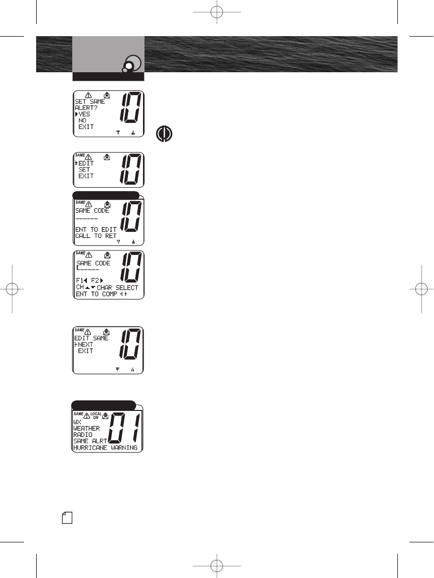
52 English
Product Features
Introduction
NOAA All Hazards/Weather
Radio and Alert, w/SAME
3. Turn the Channel knob to select alert ON.
4. Depress the Enter button and select YES to set the
same alert.
NOTE
The Weather channels may be turned Off, while
the SAME area code alerts are On or any combination
of On or Off.
5. Turn the Channel knob to select EDIT. Press Enter
button.
6. Turn the Channel knob or press the Function (F1, F2)
buttons on the radio to select the SAME alert code
number (1-10) you wish to program.
7. Press the Enter button to start entering the SAME code
number. First number entry location will start to blink.
8. Turn the Channel knob or press the Channel Up/Down
buttons on the microphone to enter the six (6) digit
SAME code number you want to enter.
9. Use the Function (F1, F2) buttons on the radio to move
to the next or previous number. Repeat steps 7 and 8
until all six digits have been entered.
10. Press the Enter button to complete the code entry.
11. Move the selection arrow to NEXT to set another SAME
alert channel. If desired. Ten total codes can be
programmed.
12. When the changes are complete, exit the WX/SAME
menu and return to the Setup menu.
Operating Your Radio
SAME Codes and Edit List
SAME Event Code Alert
8187-F80-Operation-8_MMB:F75-Operation-8 12/29/06 9:03 AM Page 52
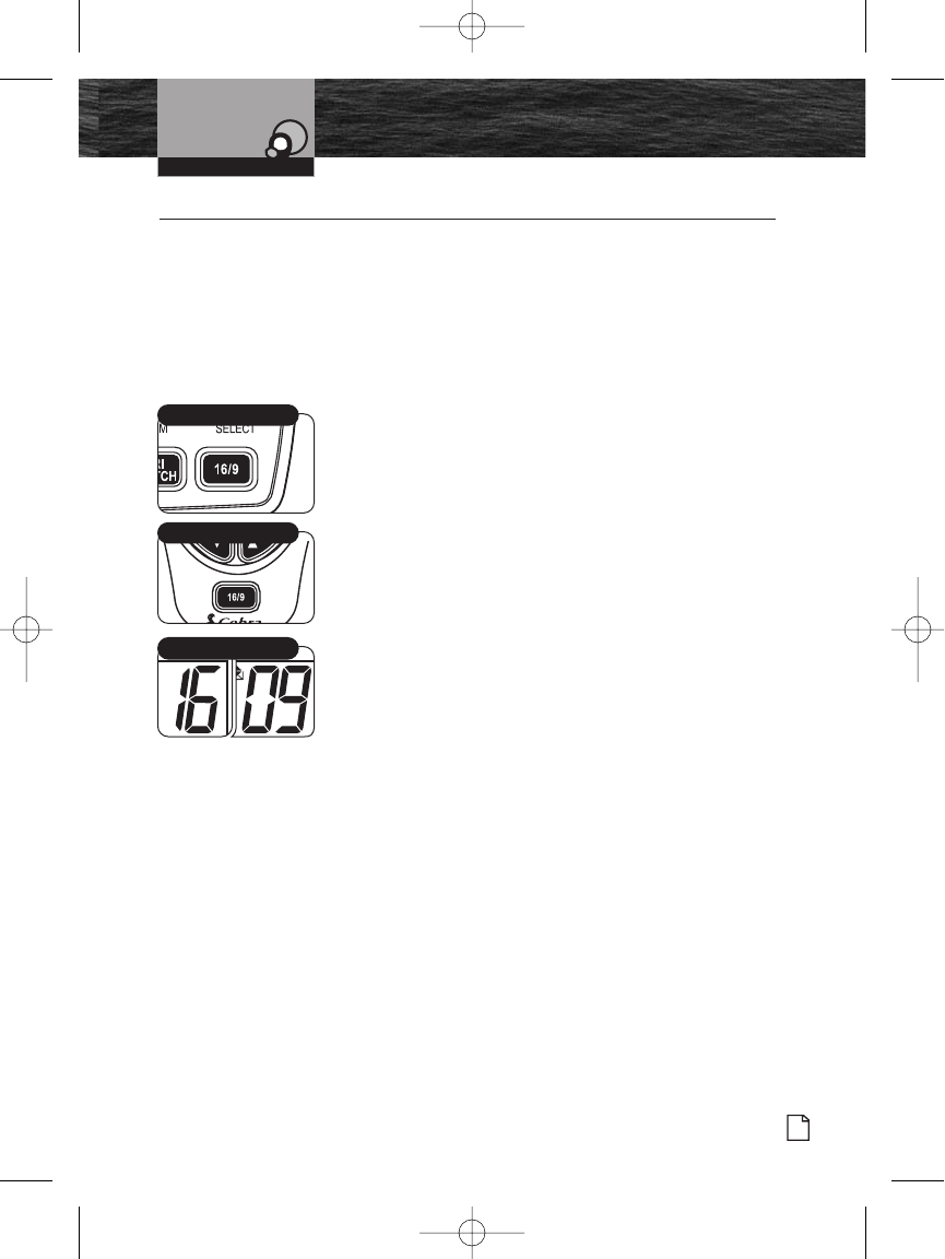
Introduction
Nothing Comes Close to a Cobra®
Product Features
53
Advanced Operation
Advanced Operation •
There are several features in the CobraMarine MR F80 VHF
radio that provide quick access to the voice calling channels
and allow monitoring more than one (1) channel at a time.
Channel 16/9
This function provides quick access to calling Channel 16 or
Channel 9 from any operational mode.
To Switch to Channel 16 or Channel 9:
1. Press the Channel 16/9 button to change to Channel 16.
2. Press the Channel 16/9 button again to change to
Channel 9.
3. Press the Channel 16/9 key again to go back to the
original working channel.
When on Channel 16 or Channel 9 in the Channel 16/9 mode,
turn the Channel Knob, press the Channel Up/Down button
on the microphone or press the Function (F1/F2) button to
change to other channels.
Operating Your Radio
Channel 16/9 Toggle
Channel 16/9 Button
Microphone 16/9 Button
8187-F80-Operation-8_MMB:F75-Operation-8 12/29/06 9:03 AM Page 53
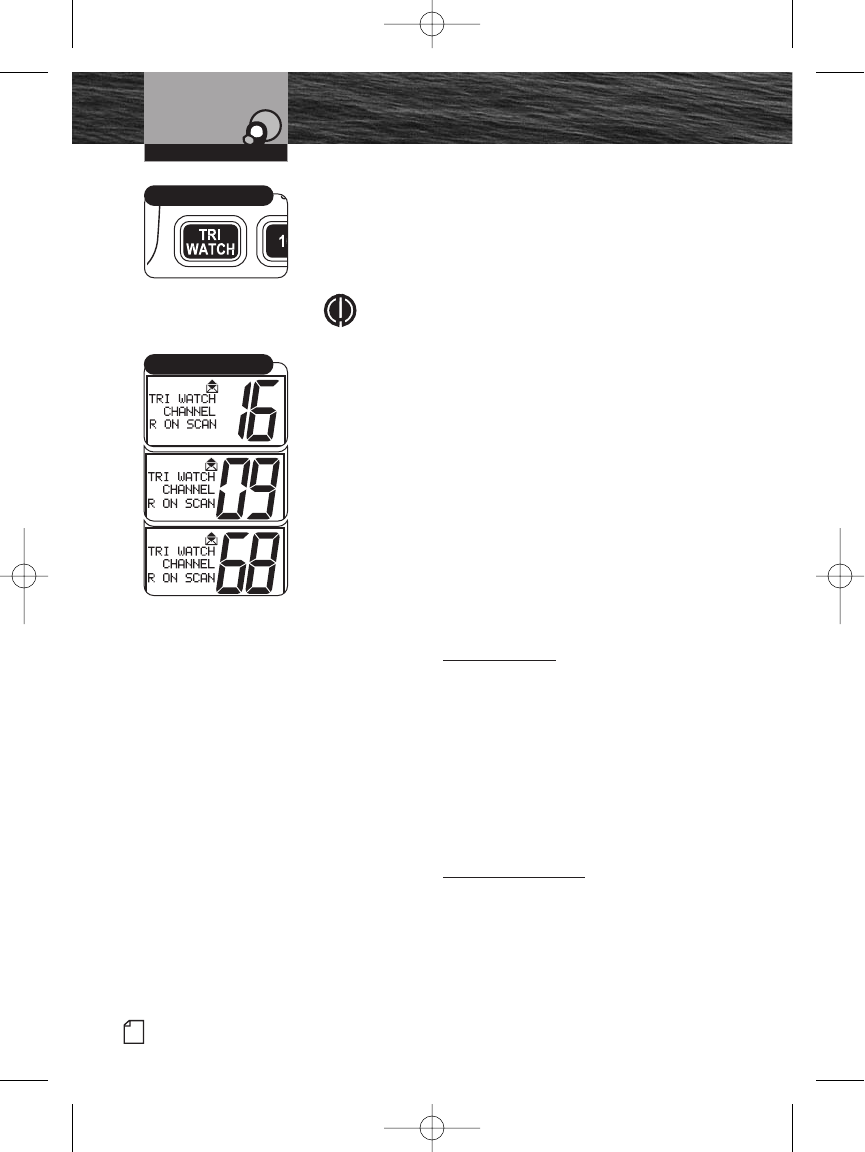
54 English
Product Features
Introduction Advanced Operation
Tri-Watch
Use Tri-Watch one-button access to scan the three (3)
channels of most importance. Channel 16 is always included
as scanned locations. The remaining locations can be set
using the following procedure.
NOTE
The radio must be squelched for the Tri-Watch to
function. See page 38 for the Squelch procedure.To
Set Tri-Watch Channels:
1. In Standby mode, turn the Channel knob or press the
Channel Up/Down buttons on the microphone to select a
2nd or 3rd scanning channel location.
2. Press the Tri-Watch button to set a new Tri-Watch
channel.
The Tri-watch screen will display on the LCD and the radio
will scan amongst Channel 16 and the other two Tri-Watch
locations you’ve selected. A signal on any one (1) of the
three (3) channels stops the scan and transmits traffic on
that channel. The channel number it is paused on displays
on the LCD.
During Tri-Watch When Receiving an Incoming
Transmission:
1. Press the Talk button to remain on that Tri-Watch
location and return to Standby mode.
2. Turn the Channel knob or press the Channel Up/Down
buttons on the microphone to resume scanning Tri-
Watch locations.
If no button is pressed, the radio automatically resumes
scanning Tri-Watch locations when an incoming
transmission is completed.
During Tri-Watch When Not Receiving an Incoming
Transmission:
Press the Talk button to communicate on the last Tri-Watch
location scanned and to return to the Standby mode.
Operating Your Radio
Tri-Watch Button
Tri-Watch Mode
8187-F80-Operation-8_MMB:F75-Operation-8 12/29/06 9:03 AM Page 54
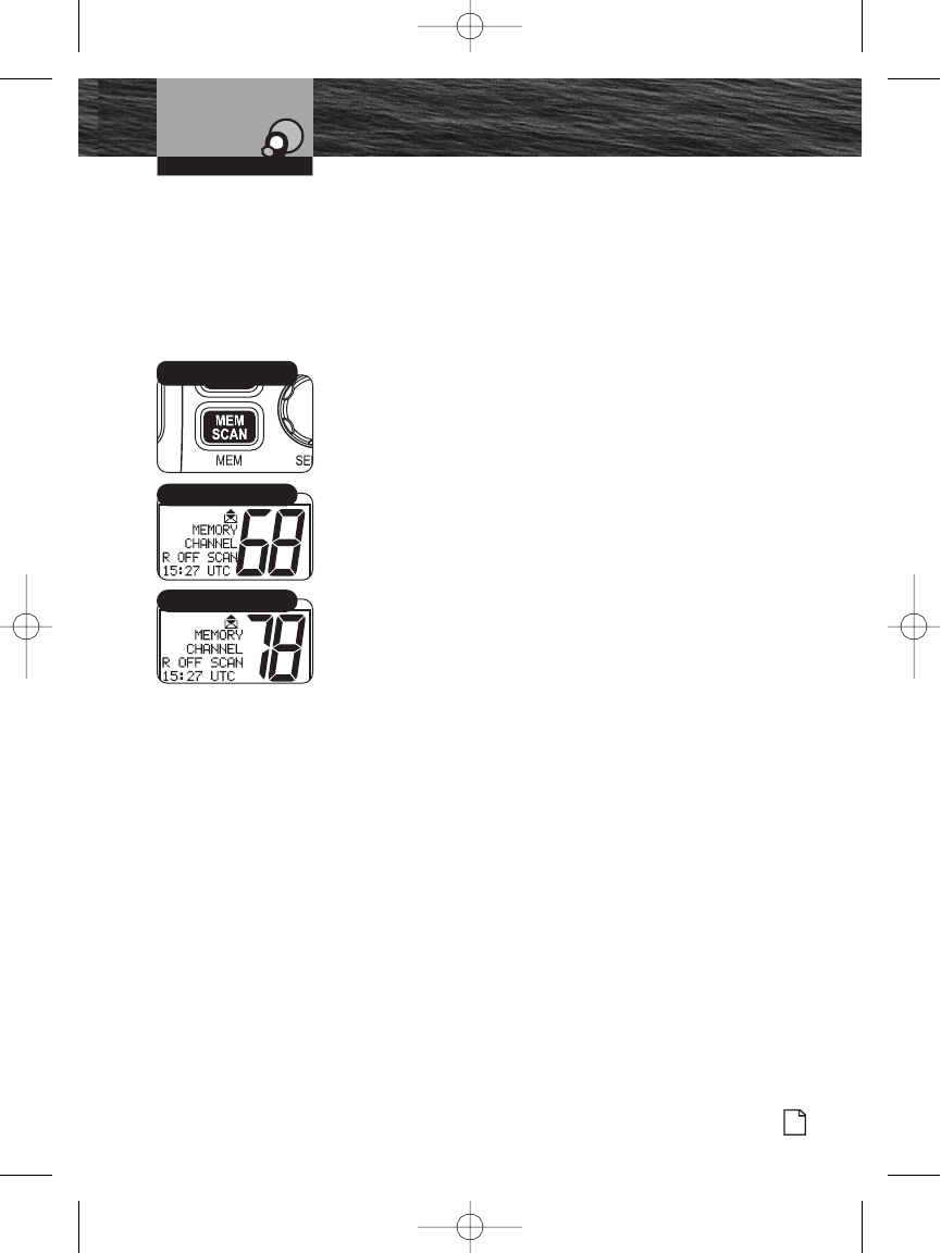
Operating Your Radio
Nothing Comes Close to a Cobra®
Advanced Operation
55
Memory Channels
Program or select an unlimited number of channels for the
Memory Scan mode.
To Program Memory Channels:
1. From Standby mode, select a channel to record using the
Channel Up/Down buttons.
2. Press and hold the Memory Scan/Memory Clear button
for three (3) seconds. The channel is recorded for
scanning and MEM (memory channel) appears on the
LCD when that channel is selected.
3. Press the Memory Scan/Memory Clear button to begin
scanning.
The radio returns to Standby mode when the Memory
Scan/Memory Clear button is pressed again.
4. Repeat steps 1 through 2 to record additional channels.
To Clear Memory Channels:
Repeat the steps above in the “To Program Memory
Channels” section, this time holding the Memory
Scan/Memory Clear button down for three (3) seconds to
clear the memory from the selected channel. Repeat as
necessary to clear additional channels.
Memory Channel
Memory Channel
Memory Scan/
Clear Button
8187-F80-Operation-8_MMB:F75-Operation-8 12/29/06 9:03 AM Page 55
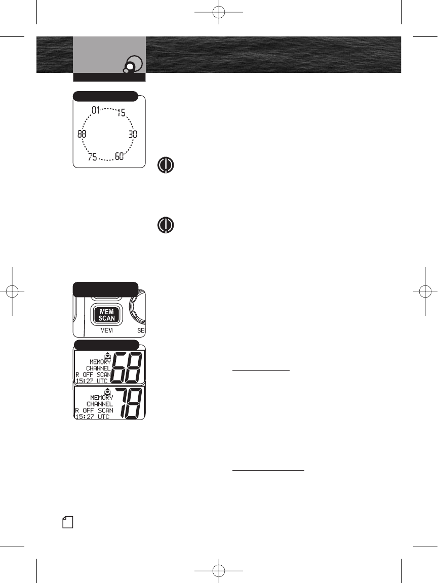
56 English
Product Features
Introduction Advanced Operation
Scanning of Memory Channels
During Memory Scan mode, the radio rapidly switches from
one recorded channel to another. When any activity is
detected, the radio stops the scan for 10 seconds for brief
listening on that channel. The scan continues until the radio
is switched out of the Memory Scan mode.
NOTE
If there are fewer than two (2) channels recorded, the
Memory Scan mode is not available. (For instructions
on recording at least two channels, see Memory
Channels, page 55.)
NOTE
The radio must be squelched for the Memory Scan
mode to function. See page 38 for Squelch
procedure.
To Enter Memory Scan:
From Standby mode, press the Memory Scan button.
The radio immediately begins to scan the channels selected
and MEM SCAN (memory scan) shows on the LCD.
To Exit Memory Scan:
From Memory Scan mode, press the Memory Scan button.
The radio returns to Standby mode on the last scanned
memory location.
During Memory Scan When Receiving an Incoming
Transmission:
1. Press the Memory Scan button to remain on that
memory location and end scanning. The radio returns to
Standby mode.
2. Press the Channel Up/Down microphone channel buttons
or turn the Channel knob to resume scanning.
If no button is pressed within 10 seconds, the radio
automatically resumes scanning.
During Memory Scan When Not Receiving an Incoming
Transmission:
Press the Talk button to communicate on the last active
channel scanned and return to Standby mode.
Operating Your Radio
Memory Scan/
Clear Button
Scanning
Memory Channel
8187-F80-Operation-8_MMB:F75-Operation-8 12/29/06 9:03 AM Page 56
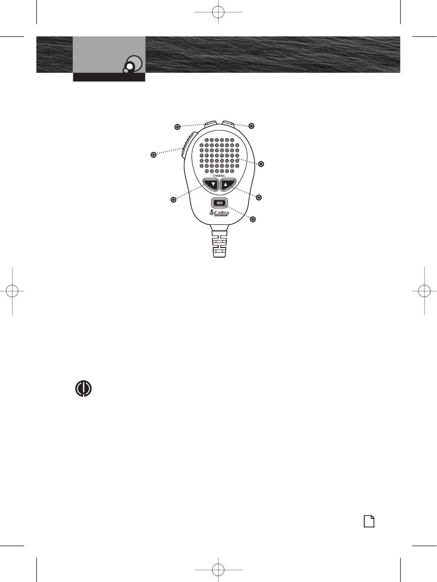
Operation from the Microphone
Use the microphone to select operation modes and accomplish approximately 90%
of all radio functions. Microphone features include:
Instant Channel 16/9 button is used to access emergency channels.
Channel Up/Down button is used to change channels.
Push to Talk (PTT) button is used to send or record a radio message.
Function (F1/F2) button is used to toggle between preset channels and/or, when
in a menu, it acts as an Escape key.
Call/Setup and Enter button is used to enter the routine Digital Selective Calling
(DSC) menu and enter the setup menu for both advanced and basic setup
functions.
NOTE
The microphone and the transceiver radio meet the JIS7 waterproof
standards.
Introduction
Nothing Comes Close to a Cobra®
Product Features
57
Advanced Operation
Operating Your Radio
Up
Button
Microphone
DSC and
Call/Setup
Enter Button
Down
Button
Push to
Talk
(PTT)
Button
Function
(F1/F2)
Button
Instant
Channel
16/9 Button
8187-F80-Operation-8_MMB:F75-Operation-8 12/29/06 9:03 AM Page 57
58 English
Product Features
Introduction
Digital Select Calling (DSC)
Setup
Digital Select Calling (DSC) Setup •
Digital Selective Calling (DSC) uses digital signals to increase messaging range. This
provides the most reliable message delivery per watt of output power. Digital signals
are less susceptible to distortion from noise and atmospheric conditions than analog
signals.
DSC equipped radios also interface with GPS and automate many operations for
sending and receiving messages. This results in compact, accurate messages and
less airwave congestion.
Setup procedures for all DSC features use the Setup menu. Refer to page 40 for
information on entering and exiting the Setup menu.
User MMSI Number
The nine (9) digit MMSI number, similar to a telephone number, is a unique identifier
for a vessel. DSC incorporates this number into every message that is Sent (Tx) or
Received (Rx). Enter the MMSI number as soon as you receive your MMSI number
from the issuing agency listed on page 9.
NOTE
The radio does not operate in the DSC mode until an official MMSI number is
entered. An error tone will sound when attempting to operate in the DSC
mode without an MMSI number.
To Enter an MMSI Number:
NOTICE
Only one MMSI number change is allowed on this unit. To prevent constant
changes and potential errors, this MMSI number limitation is on all DSC
capable radios. If the MMSI number must be changed more than once, return
the radio to Cobra Electronics for resetting. Once the radio is reset, another
MMSI number may be entered and the radio can then be used in the DSC
mode.
Operating Your Radio
8187-F80-Operation-8_MMB:F75-Operation-8 12/29/06 9:03 AM Page 58
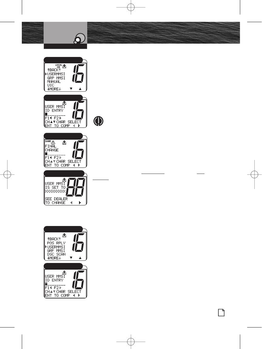
1. Enter the Setup menu and scroll to USERMMSI menu.
2. Press the Enter button. A blinking cursor displays at the
first digit under USERMMSI ID ENTRY.
3. Rotate the Channel knob to scroll through the number list
to the digit of the MMSI number being entered.
4. Press the F1 and F2 Function buttons to select the digit.
The blinking cursor moves to the next digit of the number.
5. Repeat steps 3 and 4 until all nine (9) digits of the MMSI
number are entered.
NOTE
Press the F1 Function button to backspace and the
F2 Function button to space forward. A new entry
does not automatically erase previous entries.
6. Check that the number is entered correctly.
7. Press the Enter button to return to the Setup menu.
If an MMSI Number is entered incorrectly, repeat steps 1
through 7 until correct. Remember, you only have one
attempt to reset the MMSI number or the radio must be
returned to Cobra Electronics for reset. See Product Service
on page 79 for details on how to return your radio.
Transferring a Radio to a Different Vessel
Contact the agency that issued the MMSI number to change
the vessel information associated with your MMSI number.
To View the Programmed MMSI Number at Any Time:
1. Enter the Setup menu and scroll to USERMMSI.
2. Press the Enter button and the MMSI number will appear.
3. Press the Enter button to return to the Setup menu.
Introduction
Nothing Comes Close to a Cobra®
Product Features
59
Digital Select Calling (DSC)
Setup
Operating Your Radio
USERMMSI Menu
USERMMSI ID Entry
MMSI Entry Error Message
USERMMSI Menu
USERMMSI ID Entry
MMSI Final Change
8187-F80-Operation-8_MMB:F75-Operation-8 12/29/06 9:03 AM Page 59
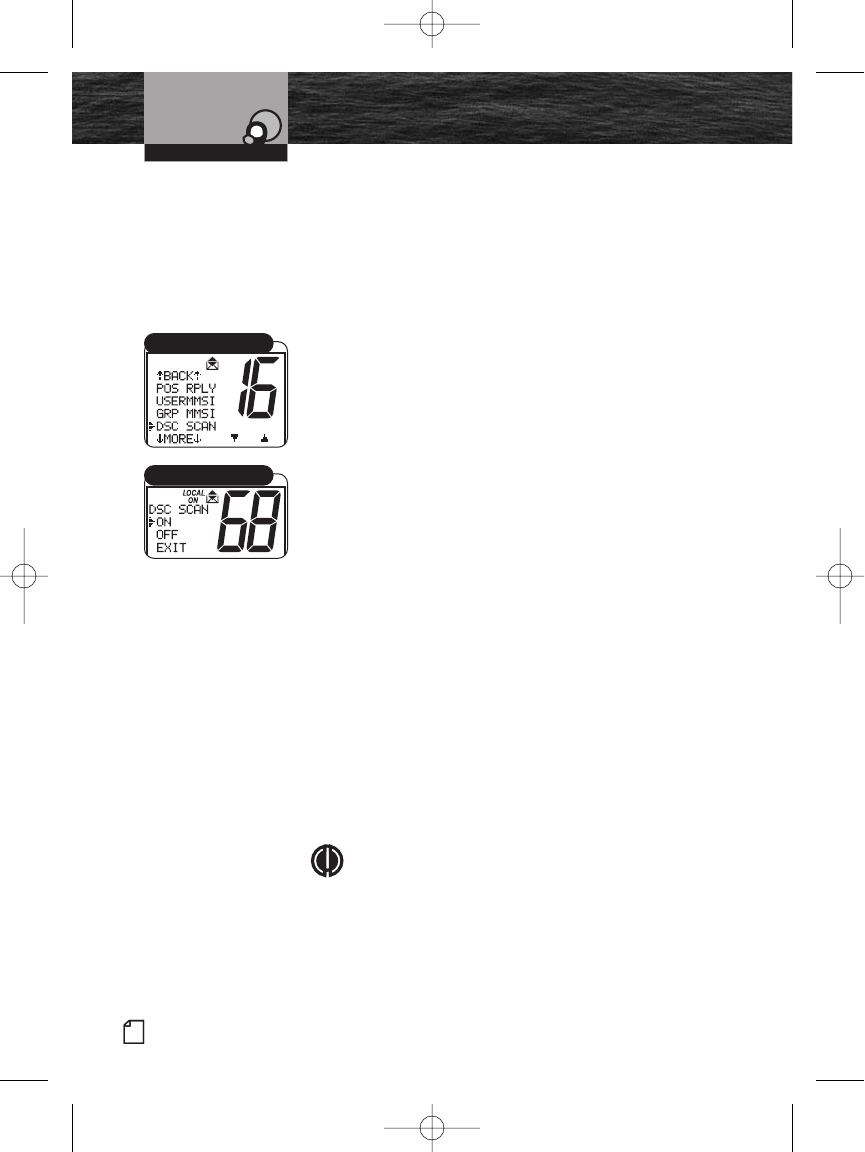
DSC Scanning
Turn DSC Scanning Off to stop the radio from scanning
Channel 70. DSC message transmissions continue but no
DSC alarms sound. No DSC messages are received unless a
distress message is transmitted. Distress message
acknowledgements are received with DSC scanning On or
Off.
To Turn DSC Scanning On or Off:
1. Enter the Setup menu and scroll to DSC SCAN menu.
2. Press the Enter button and observe the current setting —
ON or OFF.
3. Select a setting by turning the Channel knob.
4. Press the Enter button to confirm selected item and
return to the Setup menu.
Group MMSI Number
Nautical organizations like yacht clubs and regatta event
organizers can establish Group MMSI numbers. Messages
can then be automatically transmitted to all members of a
group without making individual calls.
The Group MMSI is established by modifying the MMSI
assigned to one (1) group member. To modify the MMSI
number, drop the last digit of the number and insert a zero
(0) at the beginning.
Example:
Member MMSI number 366123456 becomes Group MMSI
number 036612345.
Group MMSI numbers may be entered and changed any
time without resetting the radio. Each member of a group
must enter the group MMSI number in their radio to receive
group messages.
NOTE
ALL digits must be entered for the display to show
complete.
60 English
Product Features
Introduction
Digital Select Calling (DSC)
Setup
Operating Your Radio
DSC SCAN Menu
DSC SCAN On/Off
8187-F80-Operation-8_MMB:F75-Operation-8 12/29/06 9:03 AM Page 60
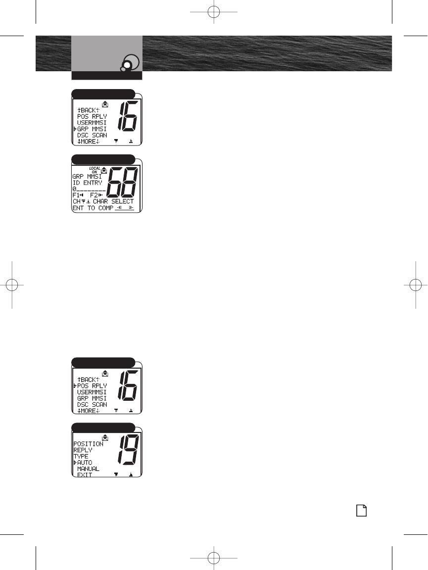
Introduction
Nothing Comes Close to a Cobra®
Product Features
61
Digital Select Calling (DSC)
Setup
To Enter a Group MMSI Number:
1. Enter the Setup menu and scroll to GRP MMSI menu.
2. Press the Enter button. A blinking cursor displays at the
first digit under GRP MMSI ID ENTRY. The leading zero
(0) will be entered automatically.
3. Turn the Channel knob or press microphone Channel
Up/Down buttons to scroll through the number list to the
digit of the Group MMSI number being entered.
4. Press the Enter button to select the digit.
5. Press the Channel Preset buttons to move within the
field.
6. Repeat steps 3, 4 and 5 until all nine (9) digits of the
Group MMSI number are entered.
7. Press the Enter button when all digits are listed.
8. Check that the number is entered correctly.
9. Press the Enter button to return to the Setup menu.
Position Request Reply Type
DSC radios with GPS send the position of a vessel to
another station. This is useful for rendezvous and rescue
situations.
Determine if the radio should automatically respond to all
Position Requests received or if it should provide a Position
Request alert and that can be manually selected and then
provide a response.
To Set the Position Request Reply Type:
1. Enter the Setup menu and scroll to POS RPLY menu.
2. Press the Enter button and observe the current setting —
AUTO or MANUAL.
3. Move the selection arrow to change the setting.
4. Press the Enter button to select the setting.
5. When the changes are complete, exit the POS RPLY
menu and return to the Setup menu.
Operating Your Radio
GRP MMSI Menu
GRP MMSI ID Entry
POS RPLY Menu
Position Reply Setting
8187-F80-Operation-8_MMB:F75-Operation-8 12/29/06 9:03 AM Page 61
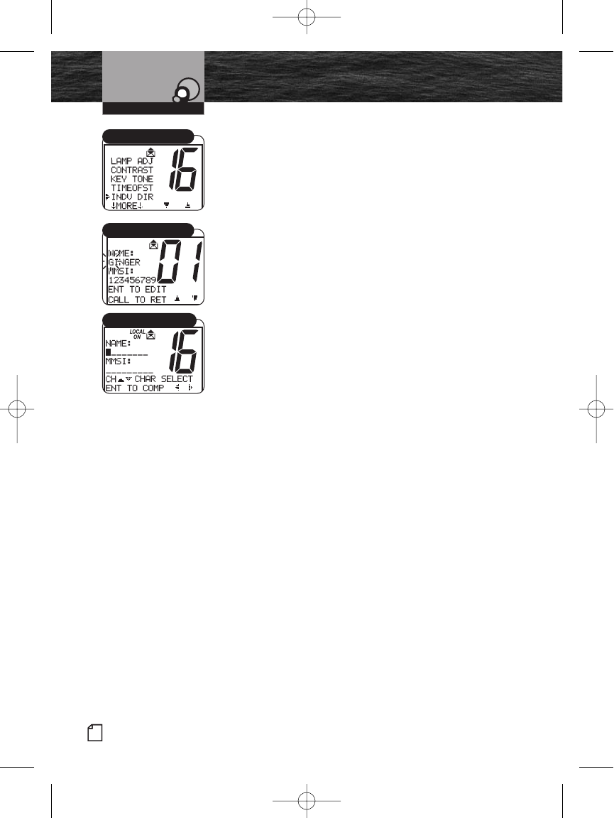
62 English
Product Features
Introduction
Digital Select Calling (DSC)
Setup
Individual Directory
DSC can be used to call another vessel or station directly.
This allows the user to make a call to a specific vessel that
could be monitoring any channel. An alarm will sound on
the receiving radio to make that station aware of your
individual call. Up to 20 names and associated MMSI
numbers may be stored in the radio for quick access.
To Enter or Edit Names or MMSI Numbers in the Individual
Directory:
1. Enter the Setup menu and scroll to INDV DIR menu.
2. Press Enter to enter the individual directory.
3. Name and MMSI contents of the current location shows
on the display
4. Press Enter to start entering Name data.
5. Rotate the Select button or the microphone up/down
buttons to select alpha or numeric characters.
6. Press F1 or F2 Function buttons to advance to the next
character.
7. Repeat steps 5 and 6 until the complete Name entry has
been made.
8. Press the Enter button to enter characters in the MMSI
field.
9. Repeat steps 5 and 6 until the complete MMSI entry has
been made.
10. Press the Enter button to accept the entry.
11. When the changes are complete, exit the INDV DIR
menu and return to the Setup menu.
Operating Your Radio
INDV DIR Menu
Name Select Menu
Individual Directory Entry
8187-F80-Operation-8_MMB:F75-Operation-8 12/29/06 9:03 AM Page 62
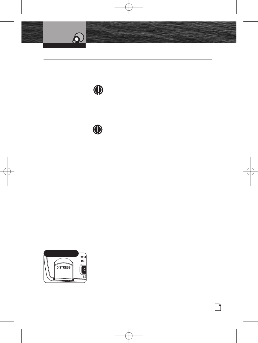
Introduction
Nothing Comes Close to a Cobra®
Product Features
63
Digital Select Calling (DSC) Operation •
The Send menu displays when the Distress button is
pressed.
NOTE
This radio follows Class-D DSC protocol with a
dedicated Channel 70 receiver.
Sending Distress Calls
Sending and receiving distress calls and acknowledgements
on Channel 70 can be a lifesaver for mariners.
NOTE
The DSC call:
Sounds the distress alarm at all receiving stations.
Informs receiving stations of the sender’s identity
(MMSI).
Informs receiving stations of the nature of the
emergency.
Informs receiving stations of sending position
when a GPS device is connected or a position is
manually entered.
DSC operation does not provide receiving stations with
information like number of persons aboard or injuries. This
specific information must be communicated by voice on
Channel 16 to the station that acknowledges a DSC Distress
call.
To Send a DSC Distress Call:
1. From Standby mode, lift the spring-loaded red door on
the transceiver and press the Distress button. The
Distress menu displays with an arrow pointing to SEND.
Digital Select Calling (DSC)
Operation
Operating Your Radio
Distress Button
8187-F80-Operation-8_MMB:F75-Operation-8 12/29/06 9:03 AM Page 63
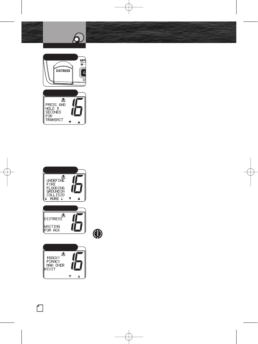
64 English
Product Features
Introduction
Digital Select Calling (DSC)
Operation
There are three (3) choices:
Send a distress call automatically, with your position, if
you are connected to a GPS. Or send the call, without
your position, if not connected to a GPS.
Include a Nature of Distress message with the distress
call.
Abort the distress call process and return to Standby
mode.
2. Choose one of the following:
Send an Automatic Distress Call:
Press and hold the Distress button.
Include a Nature of Distress Message with Distress Call:
a. Press and release the Distress button.
b. Turn the Channel knob or press the microphone
Channel Up/Down buttons to manually select from the
list of pre-programmed Nature of Distress calls —
UNDEFINE, FIRE, FLOODING, GROUNDIN, COLLISIO,
MORE.
c. Press and hold the Distress button for three (3)
seconds to transmit the distress signal.
Abort the Distress Call Process:
If the Distress button is pressed by mistake or to
discontinue resending an automatic distress message:
a. Turn the Channel knob or press the microphone
Channel Up/Down buttons to move the arrow to EXIT.
b. Press the Distress button to return to Standby mode.
NOTE
You may also press the ESC (escape) button to return
to the Standby mode.
Operating Your Radio
Distress Button
Auto Distress Send
Distress Quick Select
Distress Call Waiting
Distress Exit
8187-F80-Operation-8_MMB:F75-Operation-8 12/29/06 9:04 AM Page 64
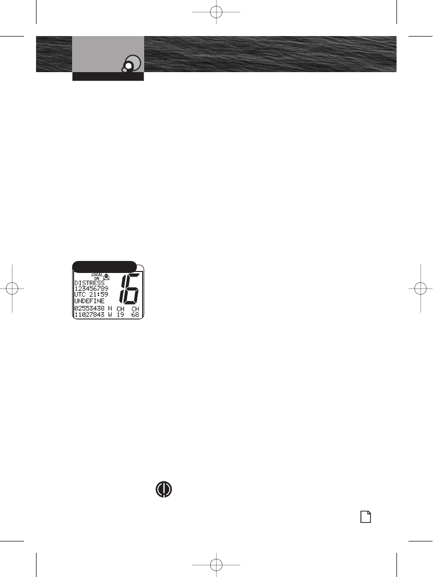
Introduction
Nothing Comes Close to a Cobra®
Product Features
65
Digital Select Calling (DSC)
Operation
The Distress alarm sounds to confirm that the message is
transmitted. At the end of the transmission, the radio
maintains a watch on Channel 16 and Channel 70 for an
acknowledgement. Press any button to turn Off the alarm
and return to Standby mode.
If an acknowledgement is received, the Distress alarm
sounds again and the responding party’s MMSI number
displays on the LCD.
If no acknowledgement is received, the radio resends
the message at approximately four (4) minute intervals
until an acknowledgement is received or the Distress
call is aborted.
Receiving Distress Calls
When a vessel is within range of a DSC Distress call, the
radio receives the call, sounds the Distress alarm, and
switches to Channel 16. All DSC calls that are received will
sound one (1) alert alarm. See pages 36-37 for descriptions
of the different alarms. Press any button to turn Off the alarm.
The received call information continues to display on the LCD.
When a Distress Call is Received:
1. Press any button to turn Off the alarm and return to
Standby mode on Channel 16.
2. Read and write down the distress information that
displays on the LCD (position data may or may not be
shown); then determine whether to answer the call.
3. Respond, if appropriate, by pressing and holding the Talk
button to transmit on Channel 16.
4. The received information is placed into the Call Log. See
page 75 for more information on viewing the Call Log.
5. If MMSI (Maritime Mobile Service Identify) matches a
contact from the Individual Directory entry stored in your
radio, the name identification displays and the alarm
sounds to identify the Name of the matching MMSI
member.
6. Press ESC after viewing the display to return to normal
Standby mode.
NOTE
The radio automatically switches to Channel 16 upon
Operating Your Radio
Distress Call MMSI
8187-F80-Operation-8_MMB:F75-Operation-8 12/29/06 9:04 AM Page 65
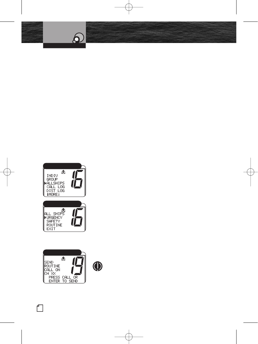
66 English
Product Features
Introduction
Digital Select Calling (DSC)
Operation
receiving a DSC Distress call and the alarm will sound
for approximately two (2) minutes. Press any button
to clear the Distress alarm instantly.
Regarding Distress Relay Calls
This radio cannot send Distress Relay calls. Only large ships
and shore stations, with specially equipped radios, can send
Distress Relay calls.
Receiving Distress Relay Calls
This radio does respond to a Distress Relay call just as it
responds to a Distress call.
Sending an All Ships Call
Use the DSC All Ships call for the same urgency and safety
purposes as the Pan and Securite voice calls as well as
sending Routine messages to all stations at once. The DSC
All Ships call reaches all stations in radio range. Use the
DSC All Ships call for urgent, but not life-threatening
situations or to broadcast a safety warning to all vessels in
the area. Use the DSC All Ships call judiciously for Routine
calls.
To Send an All Ships Call:
1. In Standby mode, select a channel to communicate a
routine call. The radio uses Channel 16 for urgent and
safety calls.
2. Press the Call/Setup button to enter the Call Setup
menu.
3. Scroll to All Ships.
4. Press Enter button for All Ships Call Select.
5. Scroll to type of call. The display shows: URGENCY,
SAFETY, ROUTINE or EXIT. Select the type of call.
6. Press the Enter button twice to send a message.
NOTE
The radio display requires confirmation before
sending Urgency and Safety calls.
Operating Your Radio
All Ships Call Menu
All Ships Call Select
All Ships Call Send
8187-F80-Operation-8_MMB:F75-Operation-8 12/29/06 9:04 AM Page 66
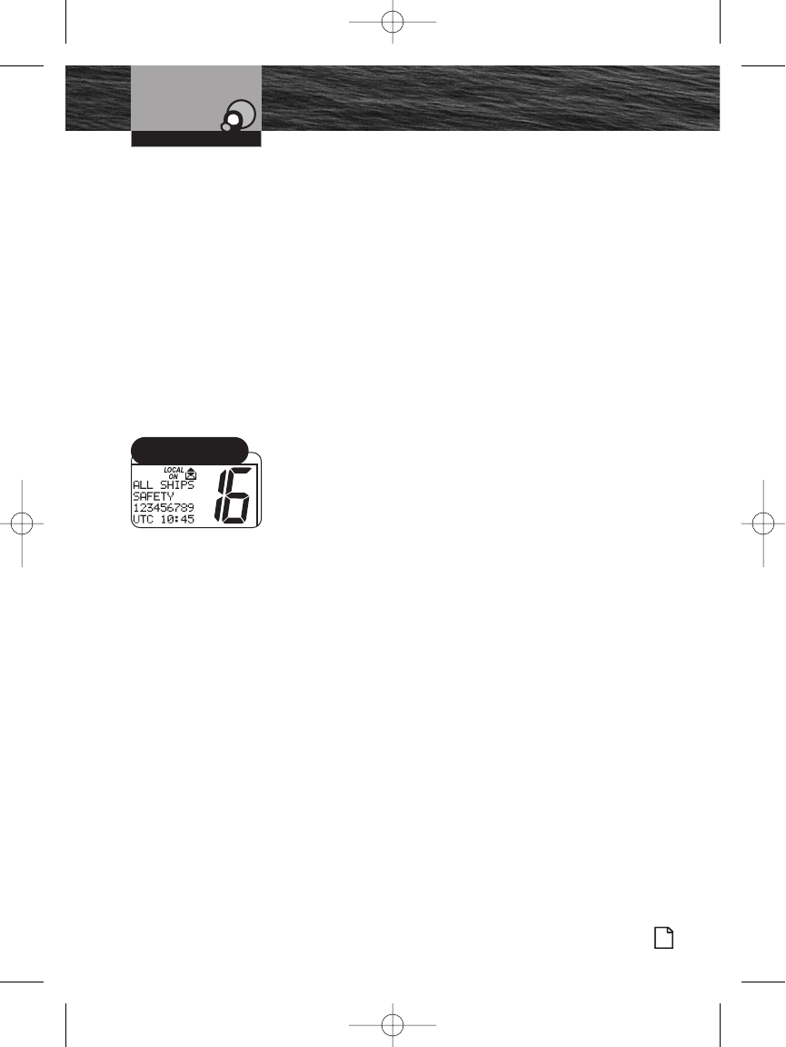
Introduction
Nothing Comes Close to a Cobra®
Product Features
67
Digital Select Calling (DSC)
Operation
5. Depending on the type of message selected, the radio
automatically switches to a voice channel.
a. After Urgency and Safety calls, the radio switches to
Channel 16. Once on channel, press the Talk button to
send the Urgency or Safety voice message.
b. After a Routine call, the radio switches to the channel
selected in step 1. Once on channel, press the Talk
button to send the Routine voice message.
DSC equipped radios that receive a DSC All Ships call
message are automatically switched to the channel selected
by the sender to hear a voice message.
To return to Standby mode, without sending a message,
scroll to EXIT and press the Enter button.
Receiving an All Ships Call
All Ships calls received from stations within range of the
radio sound the Distress alarm and switch the radio to
Channel 16.
When an All Ships Call is Heard:
1. Press any button to turn Off the alarm and return to
Standby mode.
2. Read and write down the MMSI information of the vessel
sending the call as well as the date and time of the call.
3. Listen to the incoming voice message on the channel the
radio selects for the incoming All Ships call.
Operating Your Radio
All Ships Call MMSI
Directory Match
8187-F80-Operation-8_MMB:F75-Operation-8 12/29/06 9:04 AM Page 67
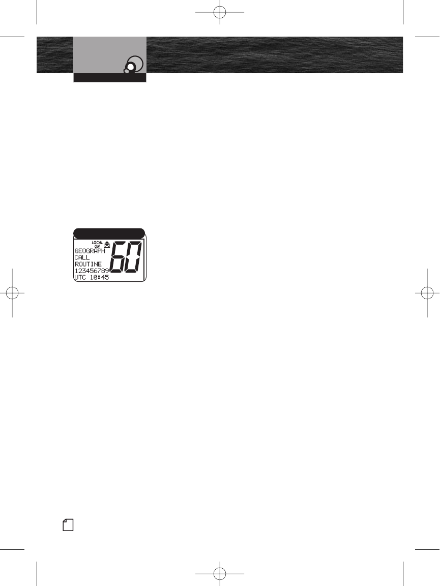
68 English
Product Features
Introduction
Digital Select Calling (DSC)
Operation
Sending a Geographical Call
This radio does not send Geographical calls. Only large
ships and shore stations with specially equipped radios send
Geographical calls.
Receiving a Geographical Call
Geographical calls are transmitted by specially equipped
radios to all stations in a particular area to alert only those
stations of the call and not stations in unaffected
geographical areas. When in an area to which a
Geographical call is made, the radio sounds the
geographical alarm and switches to the channel chosen by
the transmitting station.
When a Geographical Call Sounds:
1. Press any button to turn Off the alarm.
2. Read and write down the MMSI information of the vessel
sending the call as well as the date and time of the call.
3. Listen to the incoming voice message on the channel the
radio selects for the incoming Geographical call.
4. Place call information in Call Log.
5. Press one (1) of the following buttons to switch from the
Geographical call received to the Standby mode: Channel
16/9 button or ESC button.
Operating Your Radio
Geographical Call Received
8187-F80-Operation-8_MMB:F75-Operation-8 12/29/06 9:04 AM Page 68
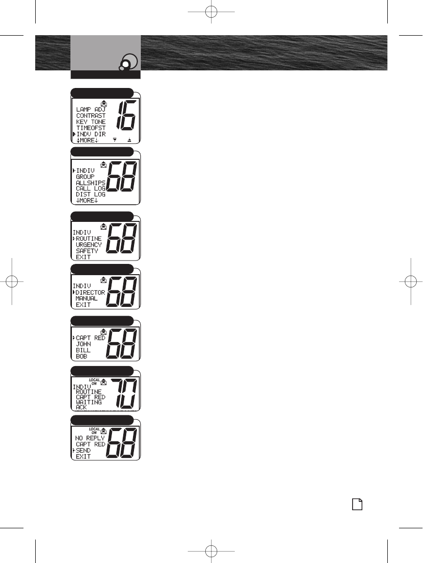
Introduction
Nothing Comes Close to a Cobra®
Product Features
69
Digital Select Calling (DSC)
Operation
Sending an Individual Call
Use the DSC Individual call feature to request
communication with one (1) exclusive station. The DSC
Individual call does not alert all other stations within range.
To Send an Individual Call:
1. In Standby mode, select a channel to communicate a call.
2. Press the Call/Setup button to enter the Call Setup
menu.
3. Press the Enter button to enter to the INDIV select
Directory.
4. Scroll to Select from Routine, Urgency or Safety as the
type of call to send.
5. Press Enter button to advance to Directory or Manual
selection. Scroll to select either method to send call.
Press Enter button again.
6. Turn the Channel knob or press the Channel Preset
buttons to select a name to call from the directory.
7. Press the Enter button to send the message or return to
Standby mode if EXIT was chosen.
If the radio called sends back an automatic DSC
response “able to comply,” the individual alarm will
sound. Wait for a voice message from the called
station.
If the radio called does not send an “able to comply”
response, the radio waits eight seconds and resends
the message.
If an “unable to comply” response or no reply is
received, the radio display asks to resend the message
or exit the menu.
At the Unavailable menu, select SEND or EXIT with the
Enter button.
If SEND is selected, the radio restarts the individual call.
If EXIT is selected, the individual location on the Call
menu displays.
Operating Your Radio
INDV DIR Menu
Individual Directory
Select Name
Send/Exit
Individual Waiting
Call Type
Menu Select
8187-F80-Operation-8_MMB:F75-Operation-8 12/29/06 9:04 AM Page 69
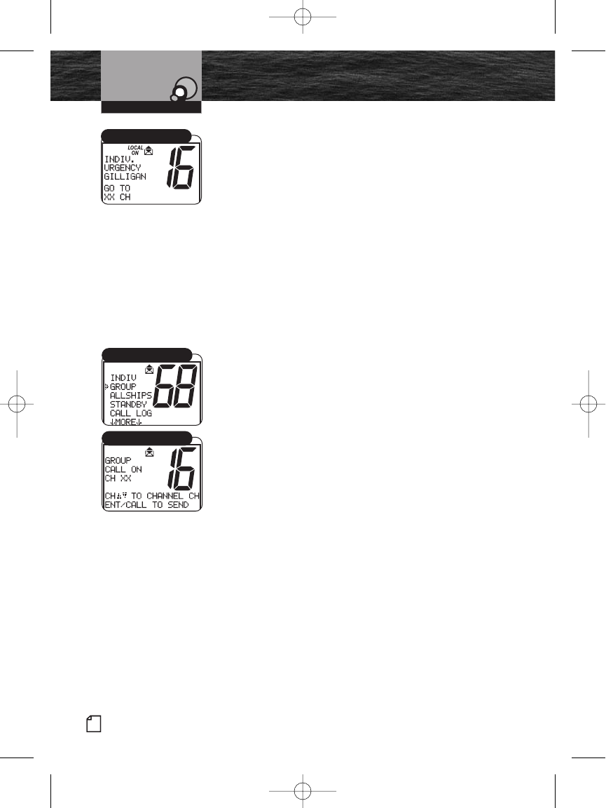
70 English
Product Features
Introduction
Digital Select Calling (DSC)
Operation
Receiving an Individual Call
When another station makes an Individual call to the radio:
The Individual alarm sounds.
The caller is identified on the LCD.
The radio switches to the channel selected by the caller.
Call information is placed in the Call Log.
To Receive an Individual Call:
Press the Talk button and greet the caller.
Sending a Group Call
Sending a Group call is like sending an Individual call, but
the group MMSI information is used and the resend and
DSC responses do not apply. See pg. 61 for creating and
entering a group MMSI.
To Send a Group Call:
1. In Standby mode, press the Call/Setup button to enter
the Group call menu.
2. Turn the Channel knob or press the microphone channel
UP/DOWN buttons to scroll to Group.
3. Press the Enter button to move to the channel select
menu.
4. Turn the Channel knob or press the microphone channel
UP/DOWN buttons to select a channel to communicate
the call.
5. Press the Enter button to send the message.
All radios switch to the channel selected in step 1.
Press and hold the Talk button to send a voice message
to everyone in the group.
Anyone in the group can transmit on the channel.
Operating Your Radio
Caller Identified
Group Calling
Send/Exit
8187-F80-Operation-8_MMB:F75-Operation-8 12/29/06 9:04 AM Page 70
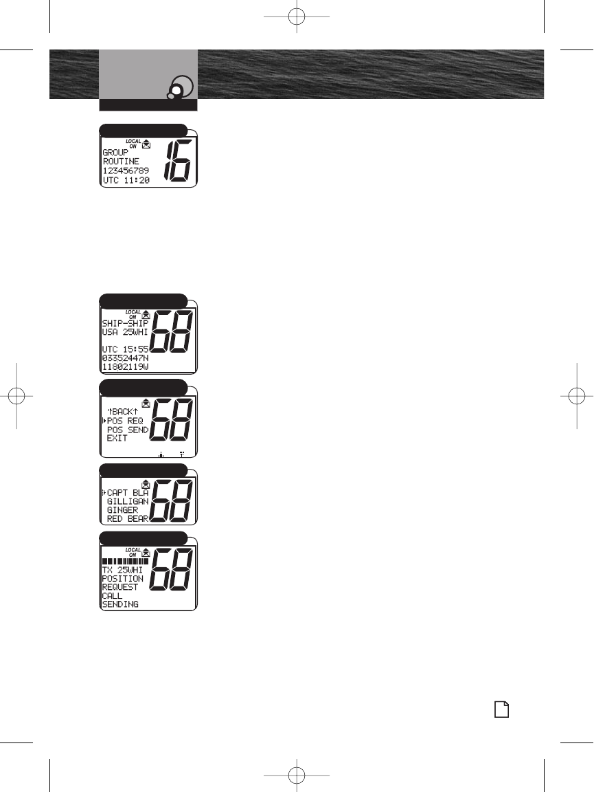
Introduction
Nothing Comes Close to a Cobra®
Product Features
71
Digital Select Calling (DSC)
Operation
Receiving a Group Call
When another station makes a Group call to the radio, the
Individual alarm sounds, the caller is identified on the LCD,
call information is placed in the Call Log, and the radio is
switched to the channel selected by the caller, similar to an
Individual call. Press any button to turn Off the alarm.
To Receive a Group Call:
1. Listen for the group voice message.
2. Press the Talk button and respond only if appropriate.
Sending a Position Request
Position Request mode enables a DSC radio to obtain the
position (latitude and longitude) of a station that has a GPS
device connected to the DSC radio at that station. In most
cases, a reply will be forthcoming. If for some reason, your
request is not acknowledged in five (5) minutes, the user
will be prompted to Resend the request or exit the menu.
To Request the Position of Another Station:
1. In Standby mode, select a channel on which you want to
communicate.
2. Press the Enter button to enter the Call Setup menu.
3. Scroll to POS RQST on the menu.
4. Press the Enter button to enter the POS RQST menu. This
will link you to the Individual Directory for you to make a
position request to one of your prior programmed
Individual Directory members.
5. Scroll to the name of the station whose position you want
to request.
6. Press the Enter button.
Your radio will send the Position Request and there will be
one (1) of three (3) possible responses:
You will receive the position.
You will receive a no position data response, meaning
the station you queried is not connected to a GPS
device and cannot send its position.
You will receive a no reply response, meaning the
operator of that station has chosen not to reply to your
request.
Operating Your Radio
Caller Identified
Individual Directory
Standby Mode
Position Request
POS RQST Menu
8187-F80-Operation-8_MMB:F75-Operation-8 12/29/06 9:04 AM Page 71
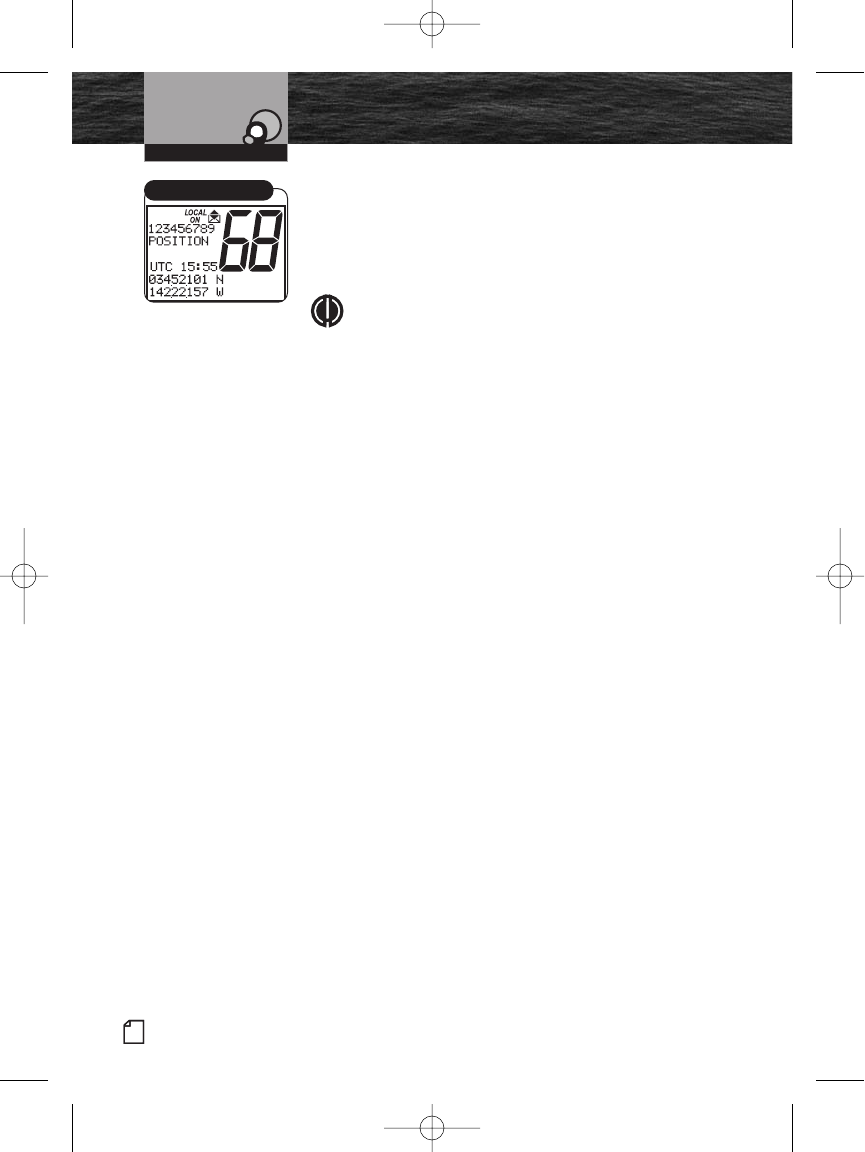
72 English
Product Features
Introduction
Digital Select Calling (DSC)
Operation
If You Receive a Position:
The requested position with the station name and MMSI will
show on your screen.
Press the Enter button to return to Standby mode after you
have noted the station’s position.
NOTE
If the MRF80 is connected properly to your Cobra
chartplotter, you will see the requested position of the
other vessel indicated on the display.
Operating Your Radio
Receiving a Position
8187-F80-Operation-8_MMB:F75-Operation-8 12/29/06 9:04 AM Page 72
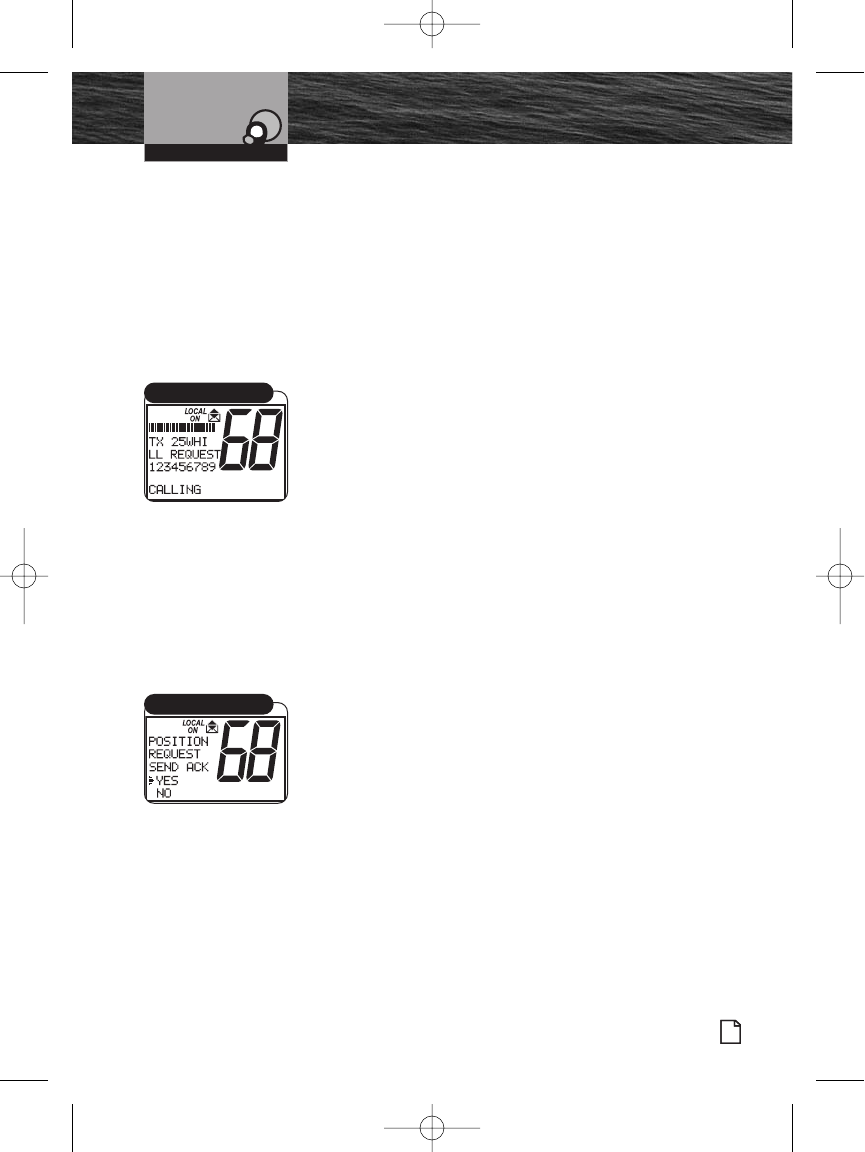
Introduction
Nothing Comes Close to a Cobra®
Product Features
73
Digital Select Calling (DSC)
Operation
Receiving a Position Request
When you went through the DSC Setup process, you set a
position request reply type. (See page 63 to change your
setting.) Depending on the setting you chose, when a
Position Request message is received, your radio will enter
either:
The Auto Reply mode.
The Manual Reply mode.
When the Radio is in Auto Reply Mode:
A position request will sound the Position Request alarm
and show the name of the requesting station on the LCD.
Your radio will automatically respond. It will send your
position, if you have a GPS device connected to your radio,
or NO POS. DATA (no position data), if you do not have a
GPS device connected.
Press any button to silence the alarm and exit the display.
When the Radio is in the Manual Reply Mode:
A position request message will sound the Position Request
alarm and show the name of the requesting station. You can
choose to:
Reply and send your position.
Exit without sending your position.
If You Choose to Reply with Your Position:
1. Turn the Channel knob, or press the microphone Channel
Up/Down buttons or press the Function (F1/F2) button to
select REPLY.
2. Press the Call/Setup or Enter button to send your
position.
3. Press any button to return to Standby mode.
If You Choose Not to Reply:
1. Turn the Channel knob, or press the microphone Channel
Up/Down buttons or press the Function (F1/F2) button to
select EXIT.
2. Press the Enter button to exit and return to Standby
mode without sending your position.
Operating Your Radio
Position Request
Reply/Exit
8187-F80-Operation-8_MMB:F75-Operation-8 12/29/06 9:04 AM Page 73
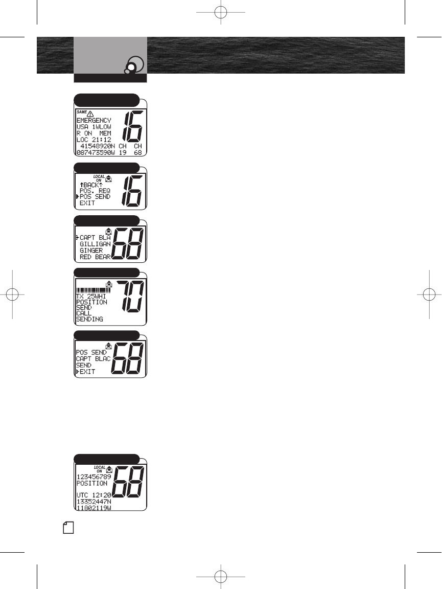
74 English
Product Features
Introduction
Digital Select Calling (DSC)
Operation
Operating Your Radio
Sending a Position Send
Position Send uses your connected GPS in similar fashion
to the Position Request function, except that you initiate the
activity to let another station know where you are.
To Send a Position Send Message:
1. In Standby mode, select a channel on which you want to
communicate.
2. Press the Enter button to enter the Call Setup menu.
3. Turn the Channel knob, or press the microphone Channel
Up/Down buttons or press the Function (F1/F2) button to
scroll to POS SEND (position send).
4. Press the Enter button to enter the Individual Directory.
5. Turn the Channel knob, or press the microphone Channel
Up/Down buttons or press the Function (F1/F2) button to
select the vessel/station to which you want to send your
position.
6. Press the Enter button to send your position.
After your position is sent, the LCD will show POS SEND
(position send). You will have two (2) choices.
Resend your position to the same station.
Exit from Position Send mode.
To Resend Your Position:
1. Turn the Channel knob, or press the microphone Channel
Up/Down buttons or press the Function (F1/F2) button to
select SEND.
2. Press the Enter button to resend your position.
To Exit From the Position Send Mode:
1. Turn the Channel knob, or press the microphone Channel
Up/Down buttons or press the Function (F1/F2) button to
select EXIT.
2. Press the Enter button to return to the Call Setup menu.
Receiving a Position Send
When another station sends you its position in Position Send
mode, the Individual alarm will sound and the station’s name
and position will be shown on the LCD. Press any button to
turn Off the alarm and return to Standby mode.
Individual Directory
Transmit Position
Send/Exit
Standby Mode
Position Send
Receive Position Send
8187-F80-Operation-8_MMB:F75-Operation-8 12/29/06 9:04 AM Page 74
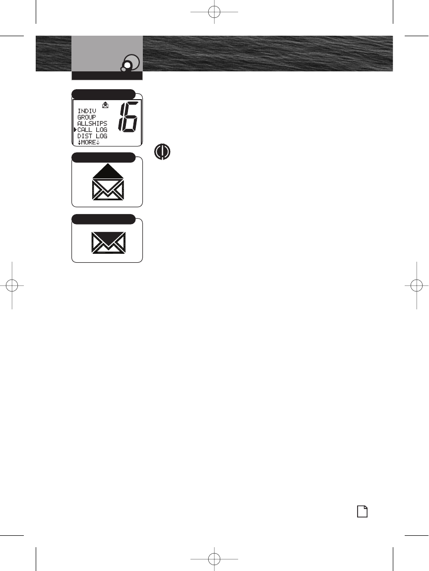
Introduction
Nothing Comes Close to a Cobra®
Product Features
75
Digital Select Calling (DSC)
Operation
Call Log and Distress Log
Call Waiting functions similarly to the Caller ID function on
your telephone. It will capture the caller’s MMSI
identification number and any other data included in a DSC
message.
NOTE
Each Call Log memory can hold up to 10 messages.
Once the memory becomes full, each new call will erase
the oldest call information on a first-in, first-out basis.
To Review Log Messages Received While in DSC Standby
Mode:
1. From Standby mode, press the Call button to enter the
Call menu.
2. Turn the Channel knob, or press the microphone Channel
Up/Down buttons to scroll to CALL LOG or DIST LOG
menu.
3. Press the Enter button to enter either LOG menu.
4. Turn the Channel knob, or press the microphone Channel
Up/Down buttons to move from message to message in
the Call Log memory.
5. Press the ESC button to return to the Call Menu.
To Clear Messages From The Log Memory:
1. Follow steps 1-3 above to enter the desired LOG.
2. Turn the Channel knob, or press the microphone Channel
Up/Down buttons to select the message you want to
delete.
3. Press the F2 button under the screen to delete the
selected message.
Repeat steps 4 through 5 to delete additional messages.
4. Press the Enter button to return to the Call Menu.
Operating Your Radio
All Messages Viewed
Call Log Menu
Unread Messages
8187-F80-Operation-8_MMB:F75-Operation-8 12/29/06 9:04 AM Page 75
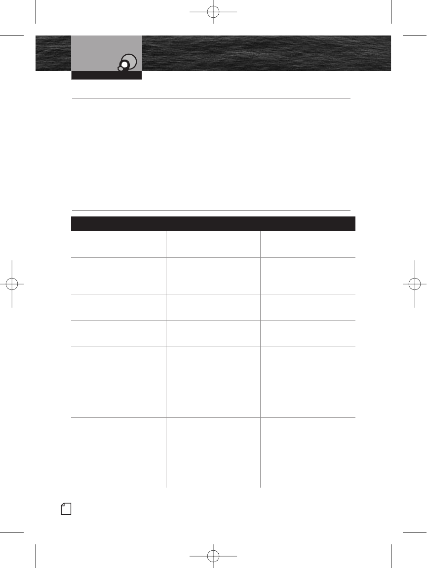
76 English
Maintenance and
Troubleshooting
Operating Your Radio
No display on LCD when
radio is turned On
Improper power
connection
Ensure power connections
are proper and secure
Will transmit at
1 watt, but not
at 25 watts
Selected channel is
limited to 1 watt
Switch to
another channel
Will not transmit Selected channel is
limited to receive only
Switch to
another channel
No sound from speaker Volume level is too low or
squelch level is too deep
Readjust volume
and squelch
No answer to calls Out of range of
other station
Signal is blocked
by terrain
Switch to high power
(25 watts) or move closer
Move until you have
a “line-of-sight” to
the other station
DSC distress
cannot be sent
MMSI
(DSC self-identification)
number is not entered
Enter your MMSI number
Problem Possible Cause(s) Solution(s)
Maintenance •
Very little maintenance is required to keep your CobraMarine VHF radio in good
operating condition.
Keep the radio clean by wiping with a soft cloth and mild detergent.
Rinse with fresh water. Do not use solvents or harsh or abrasive cleaners,
which could damage the case or scratch the LCD screen.
If the radio is exposed to salt water, rinse it in fresh water at least once
a day to prevent buildup of salt deposits, which could interfere with
button operation.
Troubleshooting •
8187-F80-Operation-8_MMB:F75-Operation-8 12/29/06 9:04 AM Page 76
Operating Your Radio
Nothing Comes Close to a Cobra®
Specifications
77
Specifications •
General
Number of Channels All U.S.A., Canadian, and International
NOAA Weather Channels
Channel Spacing 25 kHz
Modulation 5 kHz Max.
Input Voltage 13.8 VDC
Current Drain:
Stand-by 100 mA
Receive 500 mA
Transmit 5A @ High power 1A @ Low
Temperature Range -4˚F to 140˚F (-20˚C to 60˚C)
Unit Dimensions 6.375" x 3" x 6.25"
(162 mm x 76 mm x 159 mm)
Unit Weight 2 lbs., 6.8 oz. (1100 g)
Receiver
Frequency Range 156.050 to 163.275 MHz
Receiver Type Double Conversion Super-Heterodyne
Sensitivity:
20 dB Quieting 0.35 uV
12 dB Sinad 0.20 uV
Adjacent Channel Selectivity -60 dB
Intermodulation and Rejection -60 dB
Spurious and Image Rejection -60 dB
AF Output 4 Watts @ 8 Ohms
Transmitter
Frequency Range: TX 156.025 to 157.425 MHz
RF Output Power 1 and 25 Watts
Spurious Emissions -60 dB High -55 dB Low
Microphone Type Electret
Frequency Stability +/-10 ppm
FM Hum and Noise 40 dB
8187-F80-Operation-8_MMB:F75-Operation-8 12/29/06 9:04 AM Page 77

78 English
Product Features
Introduction Warranty and Trademark
Operating Your Radio
Limited 3-Year Warranty •
For Products Purchased in the U.S.A.
Cobra Electronics Corporation warrants that its CobraMarine VHF radio, and the
component parts thereof, will be free of defects in workmanship and materials
for a period of three years from the date of first consumer purchase. This
warranty may be enforced by the first consumer purchaser, provided that the
product is utilized within the U.S.A.
Cobra will, without charge, repair or replace, at its option, defective radios,
products or component parts upon delivery to the Cobra Factory Service
department, accompanied by proof of the date of first consumer purchase,
such as a duplicated copy of a sales receipt.
You must pay any initial shipping charges required to ship the product for warranty
service, but the return charges will be at Cobra’s expense, if the product is repaired
or replaced under warranty. This warranty gives you specific legal rights, and you
may also have other rights which may vary from state to state.
Exclusions: This limited warranty does not apply:
1. To any product damaged by accident.
2. In the event of misuse or abuse of the product or as a result
of unauthorized alterations or repairs.
3. If the serial number has been altered, defaced, or removed.
4. If the owner of the product resides outside the U.S.A.
All implied warranties, including warranties of merchantability and fitness for a
particular purpose are limited in duration to the length of this warranty. Cobra
shall not be liable for any incidental, consequential or other damages; including,
without limitation, damages resulting from loss of use or cost of installation.
Some states do not allow limitations on how long an implied warranty lasts and/or
do not allow the exclusion or limitation of incidental or consequential damages,
so the above limitations may not apply to you.
For Products Purchased Outside the U.S.A.
Please contact your local dealer for warranty information.
Trademark Acknowledgement •
Cobra®, CobraMarine®, Nothing Comes Close to a Cobra®, and the snake design are
registered trademarks of Cobra Electronics Corporation, USA.
Cobra Electronics Corporation™, CobraMarine™ and Rewind-Say-Again™ are
trademarks of Cobra Electronics Corporation, USA.
8187-F80-Operation-8_MMB:F75-Operation-8 12/29/06 9:04 AM Page 78

Introduction
Nothing Comes Close to a Cobra®
Product Features
79
Operating Your Radio Product Service
Product Service •
If you have any questions about operation or installing your
new CobraMarine VHF product, or if you are missing parts…
Please call Cobra first! DO NOT RETURN THIS PRODUCT TO THE STORE!
See customer assistance on page A1.
If your product should require factory service, please call Cobra first before sending
your radio. This will ensure the fastest turn-around time on your repair. You may be
asked to send your radio to the Cobra factory. It will be necessary to furnish the
following to have the product serviced and returned:
1. For warranty repair include some form of proof-of-purchase, such as a copy of a
sales receipt. If you send the original receipt, it cannot be returned.
2. Send the entire product.
3. Enclose a description of what is happening with the radio. Include a typed
or clearly printed name and address of where the radio is to be returned.
4. Pack radio securely to prevent damage in transit. If possible, use the
original packing material.
5. Ship prepaid and insured by way of a traceable carrier such as United Parcel
Service (UPS) or Priority Mail to avoid loss in transit to: Cobra Factory Service,
Cobra Electronics Corporation, 6500 West Cortland Street, Chicago, Illinois
60707 U.S.A.
6. If the radio is in warranty, upon receipt of your radio it will either be repaired
or exchanged depending on the model. Please allow approximately three (3)
to four (4) weeks before contacting Cobra for status. If the radio is out of
warranty,
a letter will automatically be sent informing you of the repair charge or
replacement charge.
If you have any questions, please call 773-889-3087 for assistance.
8187-F80-Operation-8_MMB:F75-Operation-8 12/29/06 9:04 AM Page 79
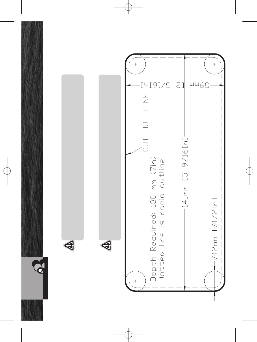
80 English
Flush Mount Template / Plantilla para montaje empotrado
Customer Service
Use the supplied template to mark and cut an opening in the flat surface.
NOTICE
Before cutting, be sure the area behind the flat surface is clear of any
instruments or wires that might be damaged in the process.
Use la plantilla suministrada para marcar y cortar el agujero en la superficie plana.
PRECAUCIÓN
Antes de cortar, compruebe que no haya instrumentos o cables en el área
detrás de la superficie plana, que puedan resultar dañados durante el proceso.
8187-F80-Operation-8_MMB:F75-Operation-8 12/29/06 9:04 AM Page 80
