Codan Radio Communications AMP-3A130 AMP-3A130-25 User Manual IM71 AMP3A1302
Codan Radio Communications AMP-3A130-25 IM71 AMP3A1302
Users manual

DANIELS
ELECTRONICS LTD.
TM
MT-3 RADIO SYSTEMS
25W AM POWER AMP
INSTRUCTION MANUAL
AMP-3
118 - 138 MHz
Covers Model: AMP-3A130-25-00
Copyright © 2002 Daniels Electronics Ltd. All rights reserved. No part of this publication may be reproduced,
stored in a retrieval system or transmitted in any form or by any means, electronic, mechanical, photocopying,
recording or otherwise, without the prior written consent of Daniels Electronics Ltd.
DE™ is a registered trademark of Daniels Electronics Ltd. registered in the United States Patent and Trademark Office.
Printing Date: Nov 2002 Daniels Electronics Ltd.
Issue Date: Nov 2002 Previous Issue Date: N/A Victoria, BC
Issue: 1Previous Issue: N/A
Document No.: IM71-AMP3A130-25 PRINTED IN CANADA

DANIELS
ELECTRONICS LTD.
TM
ii 25W AM Power Amplifier Instruction Manual IM71-AMP3A130-25
NOTE:
The user's authority to operate this equipment could be revoked through any
changes or modifications not expressly approved by Daniels Electronics Ltd.
The design of this equipment is subject to change due to continuous
development. This equipment may incorporate minor changes in detail from the
information contained in this manual.

RF Exposure Warning
S=
PG
4
π
R
2
RF Exposure Warning
This transmitting equipment conforms to SAR (Specific Absorption Rate) limits regarding exposure of human
beings to radio frequency electromagnetic energy, as defined in the following national and international standards
and guidelines:
1. Industry Canada Radio Standards Specification 102 (RSS-102), Evaluation Procedure for Mobile and
Portable Radio Transmitters with respect to Health Canada’s Safety Code 6 for Exposure of Humans to
Radio Frequency Fields;
2. Health Canada Safety Code 6, Limits of Human Exposure to Radiofrequency Electromagnetic Fields in
the Frequency Range from 3 kHz to 300 GHz 1;
3. United States Federal Communications Commission, Code of Federal Regulations; 47 CFR Part 1,
§ 1.1310 Radiofrequency radiation exposure limits; and
4. American National Standards Institute (ANSI) criteria for localized SAR in Section 4.2 of “IEEE
Standard for Safety Levels with Respect to Human Exposure to Radio Frequency Electromagnetic Fields,
3 kHz to 300 GHz”2.
Notes:
A. The SAR limit for uncontrolled exposure of persons not classed as RF and microwave exposed workers
(including the general public) for transmitter equipment operating below 10 GHz, as defined in the
references above, is 2 W/m2 (0.2 mW/cm
2 ).
B. This transmitting equipment is designed for use with an outdoor antenna with a characteristic antenna
gain of 10 dBi, typically mounted at a significant height above ground to provide for adequate signal
coverage. To ensure that the general public is not exposed to a power density above the recommended
limit of 2 W/m
2 (0.2 mW/cm
2), the equipment must be installed such that the following minimum safe
distances from the antenna are maintained:
6.0 m (19.7 ft) when configured with 25 W AM PA (at 90% modulation)
2.4 m (7.9 ft) standalone (i.e. no PA) 4 W AM TX (at 90% modulation)
C. The following power density formula has been utilized in determining minimum safe distances:
where: S = Power density (in appropriate units, e.g. W/m2 )
P = Power input to the Antenna (in appropriate units, e.g., W)
G = Power gain of the antenna in the direction of interest relative to an isotropic radiator
R = Distance to the center of radiation of the antenna (appropriate units, e.g., m)
1Minister of Public Works and Government Services, Canada 1999, Cat. H46- 2/ 99- 237E, ISBN 0- 662- 28032- 6
2ANSI/IEEE C95.1–1992, Copyright 1992 by the Institute of Electrical and Electronics Engineers, Inc., New York, New York 10017

DANIELS
ELECTRONICS LTD.
TM
25W AM Power Amplifier Instruction Manual IM71-AMP3A130-25 iii
TABLE OF CONTENTS Page
1 GENERAL................................................................................................................1-1
1.1 Introduction....................................................................................................1-1
1.2 Performance Specifications.............................................................................1-1
1.3 Physical Specifications...................................................................................1-2
2 THEORY OF OPERATION.....................................................................................2-1
2.1 General............................................................................................................2-1
2.2 Control Board Circuitry .................................................................................2-1
2.3 RF Amplifier Circuitry...................................................................................2-2
2.4 Printed Circuit board Numbering Convention................................................2-3
3 INSTALLATION AND SITE OPERATION...........................................................3-1
4 AMPLIFIER ALIGNMENT.....................................................................................4-1
4.1 Recommended Test Equipment List ..............................................................4-1
4.2 RF Amplifier Board Alignment......................................................................4-3
4.3 Control Board Alignment ...............................................................................4-5
5 ILLUSTRATIONS AND SCHEMATIC DIAGRAMS ...........................................5-1
5.1 Rack Mounting Positions...............................................................................5-1
5.2 RF Power Amplifier Block Diagram ..............................................................5-2
5.3 RF Power Amplifier Exploded View..............................................................5-3
5.4 RF Power Amplifier Board - Component Layout ........................................5-4
5.5 RF Power Amplifier Board - Schematic........................................................5-5
5.6 Control Board - Component Layout..............................................................5-6
5.7 Control Board - Schematic..............................................................................5-7
6 PARTS LISTS ..........................................................................................................6-1
6.1 RF Power Amplifier Board Electrical Parts List............................................6-1
6.2 RF Power Amplifier Board Mechanical Parts List ........................................6-3
6.3 Control Board Electrical Parts List.................................................................6-4
6.4 Control Board Mechanical Parts List.............................................................6-7
7 REVISION HISTORY..............................................................................................7-1

DANIELS
ELECTRONICS LTD.
TM
iv 25W AM Power Amplifier Instruction Manual IM71-AMP3A130-25
This Page Intentionally Left Blank

DANIELS
ELECTRONICS LTD.
TM
25W AM Power Amplifier Instruction Manual IM71-AMP3A130-25 1-1
1 GENERAL
1.1 Introduction
The AMP-3A130-25 provides the final stage of RF amplification and filtering for the AM amplifier
AMP-3A130-25, 118 - 138 MHz family. The amplifier covers 118 - 138 MHz with continuously
adjustable 10.0 to 25.0 W of output power.
The amplifier is packaged in the compact Eurostandard (5"h x 2.8"w x 7.5"d) housing, and is
robustly designed for mountain top or transportable applications. The amplifier modules use high
reliability components and each is accompanied with a complete operational test report on delivery.
1.2 Performance Specifications
Frequency: 118 to 138 MHz
Output Power: 10-25 Watts Continuous (set by VT-3A exciter)
Output Impedance: 50 Ω
Spurious & Harmonics: ≤ -80 dBc
Distortion ≤ 5% at 30% modulation
≤ 10% at 90% modulation @ 25ºC
Operating Voltage: +24 to 32 Vdc (28.0 Vdc Nominal)
Transmit Current: ≤ 3.0 A @ 25W
Standby Current: Mode 1 & 2: ≤ 2 mA (PTT or RF signal switched)
Mode 3: ≤ 200 mA (Continuous)
Load Mismatch Protection: 20:1 VSWR at all phase angles
Thermal Protection: Thermal interlock disables at 80oC (175oF)
Duty Cycle: 100%
Operating Temperature: -30oC to +60oC (-40oC to +60oC Optional)
Operating Humidity: Up to 95% R.H. @ 25oC
Front Panel Indicators: RF Power
High VSWR
Overload
Over Temperature
Exciter VT-3A130, 2.5W output for 25W
Industry Canada Approval: TBA
FCC Approval: TBA

DANIELS
ELECTRONICS LTD.
TM
1-2 25W AM Power Amplifier Instruction Manual IM71-AMP3A130-25
1.3 Physical Specifications
RF Connectors: Type N Standard
Corrosion Prevention: Anodized aluminum construction.
Stainless steel hardware.
Physical Dimensions: Width: Height: Depth:
14.2 cm (5.6") 13.1 cm (5.16") 19 cm (7.5")
Weight: 2.4 kg (5.5 lb)
Features: • Heavy Duty Aluminum Heatsink
• Thermal switched Fan (at +40˚C)
• Outputs of operating status signals:
-RF Power
- High VSWR

DANIELS
ELECTRONICS LTD.
TM
25W AM Power Amplifier Instruction Manual IM71-AMP3A130-25 2-1
2 THEORY OF OPERATION

DANIELS
ELECTRONICS LTD.
TM
2-2 25W AM Power Amplifier Instruction Manual IM71-AMP3A130-25
2.3 RF Amplifier Circuitry

DANIELS
ELECTRONICS LTD.
TM
25W AM Power Amplifier Instruction Manual IM71-AMP3A130-25 2-3
2.4 Printed Circuit board Numbering Convention
To ease troubleshooting and maintenance procedures, Daniels Electronics Limited has adopted a
printed circuit board (PCB) numbering convention in which the last two digits of the circuit board
number represent the circuit board version. For example:
• PCB number 43-912010 indicates circuit board version 1.0;
• PCB number 50002-02 indicates circuit board version 2 (no decimal versions)
All PCB's manufactured by Daniels Electronics are identified by one of the above conventions.

DANIELS
ELECTRONICS LTD.
TM
2-4 25W AM Power Amplifier Instruction Manual IM71-AMP3A130-25
This Page Intentionally Left Blank

DANIELS
ELECTRONICS LTD.
TM
25W AM Power Amplifier Instruction Manual IM71-AMP3A130-25 3-1
3 INSTALLATION AND SITE OPERATION
The AMP-3 RF power amplifier is approved for operation with the VT-3A130 exciter. A complete
M3 subrack shipped directly from the factory is normally set to the appropriate options and output
power calibration as requested by the customer. These units require no tuning.
For AMP-3 amplifiers shipped separately from the MT-3 racks, install as outlined:
1. Connect the output of the exciter to the input of the AMP-3 Amplifier with the cable
provided.
2. Connect the PTT control signal from subrack to the PTT input of the power amplifier if the
PTT activation mode is selected.
3. Connect the antenna system, key the transmitter and check the LED status indicators.
The LED indicators will only illuminate when the power amplifier is keyed and are defined as
follows:
A. RF Power - indicates that a preset RF power level is present at the power amplifier
output. The threshold level is internally adjustable for various RF output levels
over the 10-25 watt range (factory set at 10 W.)
B. High VSWR – Alarm indicating that the load impedance mismatch is high. The
threshold level is internally adjustable from 2:1 to infinite:1 (factory set at 3:1.)
C. Overload – (VSWR Overload Alarm) indicates that the RF load impedance
mismatch is extremely high. Under this condition, the DC supply voltage
(nominally +28.0 Vdc) to the PA is interrupted and the status is locked until the RF
signal from the exciter is removed. The factory threshold level is set when the load
terminal is open.
D. Over Temp - (Over Temperature Alarm) a thermostat control switch interrupts the
DC supply voltage to the PA when the RF transistor body temperature exceeds
175 ˚F (80 ˚C). Utilizing circuit hysterisis, the thermostat will reset at 167 ˚F
(75 ˚C).
The fan is activated automatically when the RF transistor body temperature reaches approximately
+40oC. The fan's operating temperature range is -20oC to +60oC. It will not operate when the
ambient temperature is below -20oC.

DANIELS
ELECTRONICS LTD.
TM
3-2 25W AM Power Amplifier Instruction Manual IM71-AMP3A130-25
This Page Intentionally Left Blank

DANIELS
ELECTRONICS LTD.
TM
25W AM Power Amplifier Instruction Manual IM71-AMP3A130-25 4-1
4 AMPLIFIER ALIGNMENT
4.1 Recommended Test Equipment List
To align the transmitter the following test equipment is recommended:
M-2/M3 rack/system monitor
Power supply: regulated 28.0 volt DC @ 5 A
Wattmeter: (e.g. Bird 4421)
Spectrum Analyzer (e.g. IFR 7550)
Alignment Tool, Johanson type 8777
Daniels Extender Card, EC-48R or EC-48UK
SWR Meter, 50 W 200 MHz
Power pad 50 ohm splitter (e.g. Socal)
Dummy Load 50Ω /50W
Dummy Loads, 2:1 and 3:1, /50W
Current Meter (5A)
DC Voltmeter

DANIELS
ELECTRONICS LTD.
TM
4-2 25W AM Power Amplifier Instruction Manual IM71-AMP3A130-25
Figure 1 RF Power Amplifier Board Alignment Locations

DANIELS
ELECTRONICS LTD.
TM
25W AM Power Amplifier Instruction Manual IM71-AMP3A130-25 4-3
4.2 RF Amplifier Board Alignment
Refer to Figure 1 for location of adjustment capacitors.
This procedure assumes the use of 2 separate subracks with the exciter transmitter in system A and
the 25W power amplifier in system B.
1. Remove the top extrusion cover housing from the exciter, set the exciter frequency at
128MHz (channel number 1200) and install the exciter in the system A of the M-2
or M-3 subrack. Remove all receivers from the subrack assembly (this will facilitate
calibration access).
2. Install the extender card in the designated location for the AMP3A130-25 Power
Amplifier (System B). Connect the RF output of the exciter to the input of the
power amplifier module and the output to a Communications Service Monitor.
3. Apply +13.8Vdc to the subrack system A and +28Vdc to the subrack system B,
activate the exciter transmitter and the power amplifier.
4. Turn the power adjustment potentiometer R19 in the exciter to achieve approximate
25W RF output. R19 is labeled "RF Level" and is accessed through the bottom of
the exciter transmitter amplifier case.
5. Monitor the RF power output and adjust C2, C3 and C10 on the RF power amplifier
board for maximum output power and minimum current. Check that the RF output
power is within 25W±1dBc (app. 20%) when the exciter frequency is set to 118,
128 and 138MHz (channel number 0000, 1200 and 2400). Note that C2 and C3 are
more effective in adjusting the output "flatness" over frequency.
6. Apply 1k/-25dBm AF signal into the balanced input of the exciter and adjust the
potentiometer R35 in the exciter to get 30% modulation. R35 is accessed through
the bottom of the exciter transmitter amplifier case, labeled Audio Level. Increase
the audio signal level to –8dBm, the modulation level should be 90±5% and the
audio distortion should be below 10%. Adjust C10 on the RF power amplifier
board for minimum audio distortion and maximum RF output power.
7. Confirm that the audio distortion is below 10% at 90% modulation and the RF
output power is within 25W±1dB at 0% modulation when the exciter frequency is
set to 118, 128 and 138MHz, respectively. Go back to step 4 if these specifications
are not met.

DANIELS
ELECTRONICS LTD.
TM
4-4 25W AM Power Amplifier Instruction Manual IM71-AMP3A130-25
Figure 2 Control Board Alignment Locations

DANIELS
ELECTRONICS LTD.
TM
25W AM Power Amplifier Instruction Manual IM71-AMP3A130-25 4-5
4.3 Control Board Alignment
1. After completion of the amplifier alignment, using the RF Level potentiometer in the
exciter, set the RF output of the power amplifier to 10 watts. LED1 (labeled RF
Power) should be on, otherwise adjust pot R1 until LED1 is just visible. This
threshold may be adjusted to any RF power output level for the AMP-3 (10 –
25W).
2. Disconnect the power amplifier RF output and terminate it with the 3:1 mismatch
load. When activating the exciter, the LED2 (labeled High VSWR) should be on,
otherwise adjust pot R19 until LED2 turns on.
3. Terminate the power amplifier RF output with a 50Ω load. LED2 should be off, if
not, slightly turn the pot R19 counter-clockwise until the LED2 is off and check that
LED2 turns on when the power amplifier RF output is terminated with the 3:1
mismatch load.
4. Disconnect the RF terminal on the load, so that the power amplifier load is open.
Once the exciter is activated, verify that LED3 (labeled Overload) is on and the
power amplifier has no RF output power. If this is not the case, shut down the
exciter, adjust R18 and reactive the exciter. This confirms that antenna VSWR
overload protection works properly.

DANIELS
ELECTRONICS LTD.
TM
4-6 25W AM Power Amplifier Instruction Manual IM71-AMP3A130-25
This Page Intentionally Left Blank

DANIELS
ELECTRONICS LTD.
TM
25W AM Power Amplifier Instruction Manual IM71-AMP3A130-25 5-1
5 ILLUSTRATIONS AND SCHEMATIC DIAGRAMS
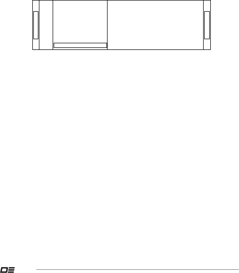
5.1 Rack Mounting Positions
8843M1
25 WATT POWER AMPLIFIER

DANIELS
ELECTRONICS LTD.
TM
5-2 25W AM Power Amplifier Instruction Manual IM71-AMP3A130-25
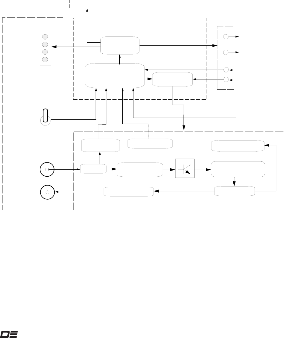
5.2 RF Power Amplifier Block Diagram
POWER AMPLIFIER BOARD
RF INPUT
SAMPLE
REAR CONNECTOR
LOGIC CONTROLLER
Driver
PWR SWITCH
CONTROL BOARD
+28VDC
I/P ATT.
RF POWER
OVER TEMP
OVERLOAD
HIGH VSWR
LED ARRAY
RF IN
PWR Supply
FRONT PANEL
PTT
REMOTE POWER
O/P FAIL
RF OUT DIR. COUPLER
POWER DETECTOR
OUTPUT MATCHING
NETWORK
INPUT MATCHING
NETWORK
LOW PASS PILTER
OFF
ON
REMOTE VSWR
COOLING FAN
THERMOSTAT
AMP3A130M2

C
C
C
POWER AMPLIFIER FRONT PANEL
HEAT SINK
FRONT BLOCK
BACK BLOCK
RF AMPLIFIER BOARD
POWER AMPLIFIER SHIELD
CONTROL BOARD
POWER AMPLIFIER
14HP CASE
Slide PCB into slot 4
D
C
C
D
C
C
C
E
E
E
E
E
G
G
E
E
A
B
B
A
A
E
E
E
E
A
COOLING FAN
CONNECTOR
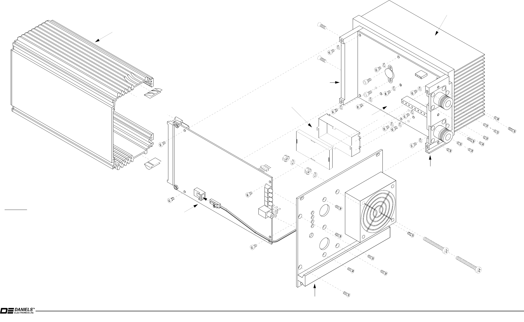
Instructions
1. Remove the 4 Front Panel screws (A).
2. Remove the Power Amplifier Case.
3. Unplug the Cooling fan connector.
4. Remove the 4 Front Panel screws (A) holding the Front Panel to the Front Block.
5. To remove the Sensor Board, remove the 4 screws (E) on the Sensor Board,
and unplug the connectors which connct the Sensor Board and RF Amplifier Board.
6. To remove the RF Amplifier Board, remove 10 screws (E) and lockwashers (F) holding the RF
Amplifier Board to the heat sink, and 2 cap screws (G) holding the RF transistor to the heat sink.
7. To remove the Front Block, remove 2 screws (D) holding the Front Block to the heat sink.
8. To remove the Back Block, remove the 2 screws (D) holding the Back Block to the heat sink.
9. To remove the Cooling Fan, remove the 2 screws (B), lockwachers (I) and nutes (H).
10. Assembly is the reverse of step1 through 8.
D
D
E
E
HI
I
H
A
A
A
E
F
F
F
F
F
F
F
F
F
F
AMP3A130M3
5.3 POWER AMPLIFIER EXPLODED VIEW
25W AM Power Amplifier Instruction Manual IM71-AMP3A130-25 5-3

5.4 RF Power Amplifier Board - Component Layout
5-4 25W AM Power Amplifier Instruction Manual IM71-AMP3A130-25

A
A
B
B
C
C
D
D
E
E
F
F
G
G
H
H
I
I
J
J
K
K
L
L
M
M
N
N
O
O
P
P
1 1
2 2
3 3
4 4
5 5
6 6
7 7
8 8
9 9
1 1
0 0
DANIELS
ELECTRONICS LTD
TM
25W AM Power AMP Instruction Manual IM71-AMP3A130-25 5-5
5.5 25W AM Power AMP RF Amplifier Board Schematic

VICTORIA B.C .
PCB No: 50104-04
DWG REV DATE:
DATE: 12 JULY 2002
DWG No: 50104
TITLE: 25W AM POWER AMPLIFIER CORTROL BOARD OUTLINE
DANIELS
ELECTRONICS LTD.
TM
5.6 Control Board - Component Layout
5-6 25W AM Power Amplifier Instruction Manual IM71-AMP3A130-25

A
A
B
B
C
C
D
D
E
E
F
F
G
G
H
H
I
I
J
J
K
K
L
L
M
M
N
N
O
O
P
P
1 1
2 2
3 3
4 4
5 5
6 6
7 7
8 8
9 9
1 1
0 0
DANIELS
ELECTRONICS LTD
TM
5.7 25W AM Power Amp Control Board Schematic
25W AM Power Amp Instruction Manual IM71-AMP3A130-25 5-7

This Page Intentionally Left Blank
25W AM Power Amplifier Instruction Manual IM71-AMP3A130-25
5-8

DANIELS
ELECTRONICS LTD.
TM
25W AM Power Amplifier Instruction Manual IM71-AMP3A130-25 6-1
6 PARTS LISTS
6.1 RF Power Amplifier Board Electrical Parts List
Ref
Desig Description Part No.

DANIELS
ELECTRONICS LTD.
TM
6-2 25W AM Power Amplifier Instruction Manual IM71-AMP3A130-25
Ref
Desig Description Part No.

DANIELS
ELECTRONICS LTD.
TM
25W AM Power Amplifier Instruction Manual IM71-AMP3A130-25 6-3
Ref
Desig Description Part No.
6.2 RF Power Amplifier Board Mechanical Parts List
Description Part No. Qty.
BACK BLOCK, DWG NO. 10596-02 TBA 1
CAP SCREW, M3x8 HEX SOCK-M2.5 5816-3M0SH08S 2
FRONT BLOCK, DWG NO. 10595-02 TBA 1
HEAT SINK, DWG NO. 10594-03 TBA 1
LID, LPF SHIELD, DWG NO. 10601-01 TBA 1
LOCKWASHER, M3, SPLIT, A2 STEEL 5814-3M0LK00S 10
PVB, TBA 1
SCREW, M3 x 8, PAN/PHIL, A2 5812-3M0PP08S 10
SCREW, M3 x 10, FLAT/PHIL, A2 TBA 4
SCREW, M3 x 6, FLAT/PHIL, A2 5812-3M0FP06S 8
WALL, LPF SHIELD, DWG NO. 10600-01 TBA 1
TAB, GROUND, M3,14.5mm L,BR/Ni, DWG 10067-01 3702-67802005 2

DANIELS
ELECTRONICS LTD.
TM
6-4 25W AM Power Amplifier Instruction Manual IM71-AMP3A130-25
6.3 Control Board Electrical Parts List
Ref
Desig Description Part No.

DANIELS
ELECTRONICS LTD.
TM
25W AM Power Amplifier Instruction Manual IM71-AMP3A130-25 6-5
Ref
Desig Description Part No.

DANIELS
ELECTRONICS LTD.
TM
6-6 25W AM Power Amplifier Instruction Manual IM71-AMP3A130-25
Ref
Desig Description Part No.

DANIELS
ELECTRONICS LTD.
TM
25W AM Power Amplifier Instruction Manual IM71-AMP3A130-25 6-7
6.4 Control Board Mechanical Parts List
Description Part No. Qty. Ref. Desig
FUSE CLIP, RIVET MOUNT TBA 2
PA FRONT PANEL, DWG 10582-03 TBA 1
HANDLE/NAMEPLATE KIT, 28HP, GREY TBA 1
FAN, 12VDC, 60X60X25mm, 20CFM TBA 1
M33455-16, NIDEC
CONN., .100”, CRIMP HOUSING, 2CCT TBA 1
50-57-9402, MOLEX 1
TERMINAL, CRIMP, FEM., 22-24,Au 5021-TF22B002 1
GUARD, FOR 60mm SQ. FAN, STEEL 6519-60602R0S 1
TUBING, TFE-260C, 8AWG T/W, CLR 7610-260C08TW 8.5”
FUSE, 8 AMP FAST-BLO 5604-5GAGC080 1 F1
CASE, 14HP RF PLUG-IN, MT-3 PA TBA 1
DWG 10581-03
GASKET, BeCu, 3FINGER, 71",CLIP 5630-12023250 1
SCREW, M4 X 35, PAN/PHIL., A2 5812-4M0PP35S 2
LOCKWASHER, M4, SPLIT,A2 STEEL 5814-4M0LK00S 2
NUT, M4, HEX, 6.9mm FLATS, A2 5813-4M0HX69S 2
NUT, PRESS,M2.5, 5.6mmOD, PC MNT 5833-T2M55615 2
SCREW, M3 x 8,OVAL C/S/PHIL,A2 5812-3M0VP08S 7
SCREW, M3 x 8, PAN/PHIL, A2 5812-3M0PP08S 4
SCREW, M2.5 x 10 PAN/PHIL, A2 5812-2M5PP10S 2

DANIELS
ELECTRONICS LTD.
TM
6-8 25W AM Power Amplifier Instruction Manual IM71-AMP3A130-25
This Page Intentionally Left Blank

DANIELS
ELECTRONICS LTD.
TM
25W AM Power Amplifier Instruction Manual IM71-AMP3A130-25 7-1
7 REVISION HISTORY
IssueiIssued Revised Details
1 July 2002 First Issue
i When a revision letter is assigned, it indicates that a revised issue has been released for in-house
distribution only.

DANIELS
ELECTRONICS LTD.
TM
7-2 25W AM Power Amplifier Instruction Manual IM71-AMP3A130-25
This Page Intentionally Left Blank