user manual

HF RADIO COMMUNICATIONS
INSTALLATION HANDBOOK
Power Amplifier
3160
No part of this handbook may be reproduced, transcribed,
translated into any language or transmitted in any form
whatsoever without the prior written consent of Codan
Limited.
© Copyright 2008, 2009 Codan Limited.
Codan part number 15-04157-EN Issue 2, February 2009
Brand, product, and company names mentioned in this
document are trademarks or registered trademarks of their
respective holders.
The English version takes precedence over any translated
versions.

Power Amplifier 3160 Installation Handbook i
Table of contents
Introduction
1Overview
General . . . . . . . . . . . . . . . . . . . . . . . . . . . . . . . . . . . . . . . . . . . . . . . . . . . . . 4
Power supply options . . . . . . . . . . . . . . . . . . . . . . . . . . . . . . . . . . . . . . . . . . 6
Typical layouts . . . . . . . . . . . . . . . . . . . . . . . . . . . . . . . . . . . . . . . . . . . . . . . 8
Care and safety guidelines . . . . . . . . . . . . . . . . . . . . . . . . . . . . . . . . . . . . . 13
Compatibility . . . . . . . . . . . . . . . . . . . . . . . . . . . . . . . . . . . . . . . . . . . . . . . 14
2 Installing the 3160
Disclaimer. . . . . . . . . . . . . . . . . . . . . . . . . . . . . . . . . . . . . . . . . . . . . . . . . . 16
What you need to consider . . . . . . . . . . . . . . . . . . . . . . . . . . . . . . . . . . . . . 17
Basic layout. . . . . . . . . . . . . . . . . . . . . . . . . . . . . . . . . . . . . . . . . . . . . . 17
Stacked layout . . . . . . . . . . . . . . . . . . . . . . . . . . . . . . . . . . . . . . . . . . . . 18
Mobile station . . . . . . . . . . . . . . . . . . . . . . . . . . . . . . . . . . . . . . . . . . . . 18
Fixed station . . . . . . . . . . . . . . . . . . . . . . . . . . . . . . . . . . . . . . . . . . . . . 20
Mounting . . . . . . . . . . . . . . . . . . . . . . . . . . . . . . . . . . . . . . . . . . . . . . . . 20
Grounding . . . . . . . . . . . . . . . . . . . . . . . . . . . . . . . . . . . . . . . . . . . . . . . 20
Installing the 3160 in a basic layout . . . . . . . . . . . . . . . . . . . . . . . . . . . . . . 21
Installing the 3160 in a stacked layout . . . . . . . . . . . . . . . . . . . . . . . . . . . . 22
Attaching the 2110 amplifier adaptor panel to the rear of the
transceiver cradle . . . . . . . . . . . . . . . . . . . . . . . . . . . . . . . . . . . . . . . . . . . . 24
Attaching the 3160, voltage regulator and external speaker to a
mounting surface. . . . . . . . . . . . . . . . . . . . . . . . . . . . . . . . . . . . . . . . . . . . . 26
Attaching a suitable power supply to the power supply cover . . . . . . . . . . 27
Attaching the power amplifier mounting bracket to the transceiver
cradle. . . . . . . . . . . . . . . . . . . . . . . . . . . . . . . . . . . . . . . . . . . . . . . . . . . . . . 27
Attaching the 3160 and external speaker to the power amplifier
mounting bracket . . . . . . . . . . . . . . . . . . . . . . . . . . . . . . . . . . . . . . . . . . . . 31
Connecting the equipment . . . . . . . . . . . . . . . . . . . . . . . . . . . . . . . . . . . . . 33
Setting up the transceiver . . . . . . . . . . . . . . . . . . . . . . . . . . . . . . . . . . . . . . 34

Table of contents
ii Power Amplifier 3160 Installation Handbook
Grounding the 3160 . . . . . . . . . . . . . . . . . . . . . . . . . . . . . . . . . . . . . . . . . . . 34
Installing the station. . . . . . . . . . . . . . . . . . . . . . . . . . . . . . . . . . . . . . . . . . . 35
3 Specifications
4 Accessories
Appendix A—Connectors
Appendix B—Compliance
Introduction . . . . . . . . . . . . . . . . . . . . . . . . . . . . . . . . . . . . . . . . . . . . . . . . . 46
European R&TTE Directive . . . . . . . . . . . . . . . . . . . . . . . . . . . . . . . . . . . . 46
EMC and safety notices. . . . . . . . . . . . . . . . . . . . . . . . . . . . . . . . . . . . . . . . 47
C-tick approval . . . . . . . . . . . . . . . . . . . . . . . . . . . . . . . . . . . . . . . . . . . . . . 48
FCC compliance . . . . . . . . . . . . . . . . . . . . . . . . . . . . . . . . . . . . . . . . . . . . . 49
FCC Part 90 certification . . . . . . . . . . . . . . . . . . . . . . . . . . . . . . . . . . . . 49
FCC Part 15 compliance . . . . . . . . . . . . . . . . . . . . . . . . . . . . . . . . . . . . 49
Compliance with RF exposure standards. . . . . . . . . . . . . . . . . . . . . . . . 50
Operating instructions to control RF exposure . . . . . . . . . . . . . . . . . . . 50
Mobile antennas . . . . . . . . . . . . . . . . . . . . . . . . . . . . . . . . . . . . . . . . . . . 51
Approved accessories. . . . . . . . . . . . . . . . . . . . . . . . . . . . . . . . . . . . . . . 51
Contact information . . . . . . . . . . . . . . . . . . . . . . . . . . . . . . . . . . . . . . . . 51
IC approval . . . . . . . . . . . . . . . . . . . . . . . . . . . . . . . . . . . . . . . . . . . . . . . . . 52
Register of hazardous substances . . . . . . . . . . . . . . . . . . . . . . . . . . . . . . . . 53
Appendix C—Definitions
Standards and icons . . . . . . . . . . . . . . . . . . . . . . . . . . . . . . . . . . . . . . . . . . . 55
Acronyms and abbreviations . . . . . . . . . . . . . . . . . . . . . . . . . . . . . . . . . . . . 56
Glossary . . . . . . . . . . . . . . . . . . . . . . . . . . . . . . . . . . . . . . . . . . . . . . . . . . . . 57
Units. . . . . . . . . . . . . . . . . . . . . . . . . . . . . . . . . . . . . . . . . . . . . . . . . . . . . . . 58
Unit multipliers . . . . . . . . . . . . . . . . . . . . . . . . . . . . . . . . . . . . . . . . . . . . . . 59
About this issue . . . . . . . . . . . . . . . . . . . . . . . . . . . . . . . . . . . . . . . . . . . . . . 60
Index

Power Amplifier 3160 Installation Handbook iii
List of figures
Figure 1: 3160 Power Amplifier . . . . . . . . . . . . . . . . . . . . . . . . . . . 4
Figure 2: Power supply from a 3020 Transceiver Supply . . . . . . . . 6
Figure 3: Power supply from a 12 V battery . . . . . . . . . . . . . . . . . . 7
Figure 4: Power supply from a 24 V battery via a voltage
regulator . . . . . . . . . . . . . . . . . . . . . . . . . . . . . . . . . . . . . . 7
Figure 5: Basic layout . . . . . . . . . . . . . . . . . . . . . . . . . . . . . . . . . . 10
Figure 6: Stacked layout . . . . . . . . . . . . . . . . . . . . . . . . . . . . . . . . 12
Figure 7: Process for installing the 3160 in a basic layout . . . . . . 21
Figure 8: Process for installing the 3160 in a stacked layout. . . . . 23
Figure 9: 2110 amplifier adaptor panel and cradle . . . . . . . . . . . . 24
Figure 10: Power supply cover, cradle, and power amplifier
mounting bracket . . . . . . . . . . . . . . . . . . . . . . . . . . . . . . 28
Figure 11: Power supply cover, cradle, power amplifier
mounting bracket, interface adaptor, and coaxial
cable . . . . . . . . . . . . . . . . . . . . . . . . . . . . . . . . . . . . . . . . 29
Figure 12: Holes in the power amplifier mounting bracket . . . . . . . 31
Figure 13: 3160 and power amplifier mounting bracket . . . . . . . . . 32
Figure 14: Dimensions . . . . . . . . . . . . . . . . . . . . . . . . . . . . . . . . . . . 39
Figure 15: Front view of the 12-way connector on the 3160. . . . . . 43
Figure 16: Front view of the 6-way connector on the 2110
amplifier adaptor panel. . . . . . . . . . . . . . . . . . . . . . . . . . 44

List of figures
iv Power Amplifier 3160 Installation Handbook
This page has been left blank intentionally.

Power Amplifier 3160 Installation Handbook v
List of tables
Table 1: Functional specifications . . . . . . . . . . . . . . . . . . . . . . . . 37
Table 2: Dimensions . . . . . . . . . . . . . . . . . . . . . . . . . . . . . . . . . . . 39
Table 3: Weights for accessories . . . . . . . . . . . . . . . . . . . . . . . . . 40
Table 4: Accessories for the 3160 Power Amplifier . . . . . . . . . . 41
Table 5: Pinouts for the 12-way connector on the 3160 . . . . . . . . 43
Table 6: Pinouts for the 6-way connector on the 2110
amplifier adaptor panel. . . . . . . . . . . . . . . . . . . . . . . . . . 44
Table 7: 有毒有害物质列表 (Register of hazardous
substances) . . . . . . . . . . . . . . . . . . . . . . . . . . . . . . . . . . . 53

List of tables
vi Power Amplifier 3160 Installation Handbook
This page has been left blank intentionally.

Power Amplifier 3160 Installation Handbook 1
Introduction
This handbook is for installers of the 3160 Power Amplifier. It
assumes that you have experience in installing RF equipment.
This handbook contains the following sections:
Section 1 Overview—provides an overview of the 3160,
typical layouts, care and safety, and
compatibility
Section 2 Installing the 3160—provides guidance on how
to position, install, and earth the 3160
Section 3 Specifications—provides the common
operational, environmental, and physical
specifications of the 3160
Section 4 Accessories—lists the accessories available for
the 3160
Appendix A Connectors—provides the pinouts for Codan-
specific connectors
Appendix B Compliance—provides compliance information
and safety notices for the 3160
Appendix C Definitions—explains the terms and
abbreviations used in this handbook
There is an index at the end of this handbook.

Introduction
2 Power Amplifier 3160 Installation Handbook
This page has been left blank intentionally.

Overview
4 Power Amplifier 3160 Installation Handbook
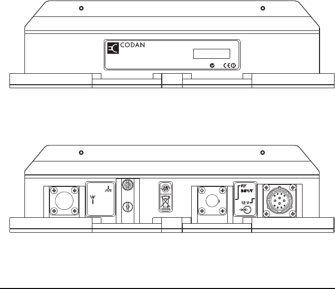
General
The 3160 Power Amplifier is designed to provide 125 W
transmitting power for a 2110M or 2110 Manpack
Transceiver. The 3160 provides 12 V DC to the transceiver
from a suitable power source. When the 3160 is connected
into the transceiver system, it is automatically detected when
the transceiver is switched on.
Figure 1: 3160 Power Amplifier
NOTE A 100 W option is available.
NOTE
For information on hardware and software
compatibility requirements see page 14,
Compatibility.
3160 Power Amplifier Serial No.Serial No.Serial No.Serial No.Serial No.
N101N101N101N101N101

Overview
Power Amplifier 3160 Installation Handbook 5
A typical 3160 Power Amplifier installation comprises:
• a 2110M Manpack Transceiver (build standard A or
later), or a 2110 Manpack Transceiver (build standard H
or later) with firmware V4.91 or later
• a 3160 Power Amplifier
• a 2110 series Manpack Transceiver cradle with interface
adaptor and external speaker
• a 2110 amplifier adaptor panel
• a power adaptor cable
• a coaxial cable
• a 12 V DC power source with appropriate cables
• an antenna system with appropriate cables and power
rating
• a grounding system
Optional equipment for the system includes:
• a power amplifier mounting bracket
• a power supply cover
•a fan
• an external antenna tuner
Overview
6 Power Amplifier 3160 Installation Handbook
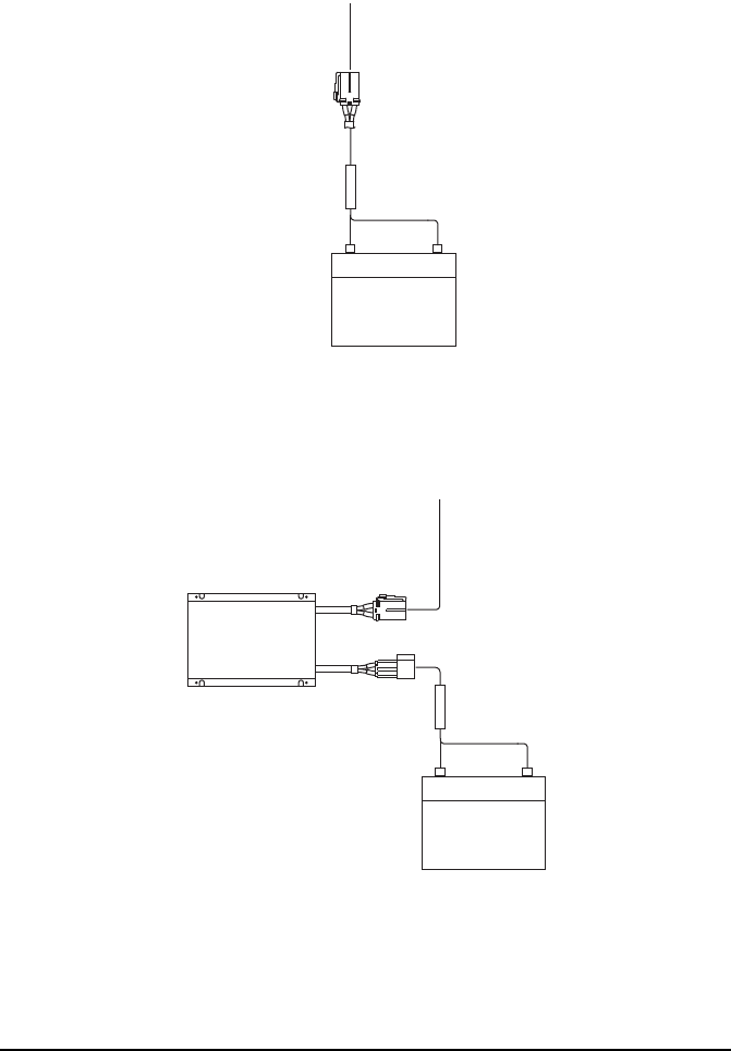
Power supply options
The 3160 Power Amplifier requires a 12 V DC supply. This
may be supplied by one of the following sources:
• 3020 Transceiver Supply (fixed station only; this
requires connection to the AC mains supply)
• 12 V DC vehicle battery (see Figure 3 on page 7)
• 24 V DC vehicle battery via a 24 V to 12 V voltage
regulator (see Figure 4 on page 7)
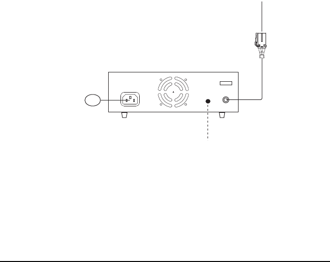
Figure 2: Power supply from a 3020 Transceiver
Supply
NOTE
You can mount the 3020 Transceiver Supply or
the voltage regulator within a power supply
cover (Codan part number 15-00147).
earth strap
08-04515
3020 Transceiver Supply
AC
power adaptor cable
08-06808-xxx
Overview
Power Amplifier 3160 Installation Handbook 7
Figure 3: Power supply from a 12 V battery
Figure 4: Power supply from a 24 V battery via a
voltage regulator
12 V
battery
+
fuse
power adaptor cable
08-06808-xxx
24 V
battery
+
24 V to 12 V
voltage
regulator
15-00508
fuse
power adaptor cable
08-06808-xxx
(or two 12 V batteries)

Overview
8 Power Amplifier 3160 Installation Handbook
Typical layouts
The 2110M or 2110 Manpack Transceiver and a 3160 Power
Amplifier may be installed in a mobile station or a fixed
station.
The equipment may be arranged in one of two layouts:
• basic layout, in which items are located separately and
bolted down, if required (see Figure 5 on page 10)
• stacked layout, in which all items are bolted together in a
stack using a mounting bracket, and optional power
supply cover (see Figure 6 on page 12)
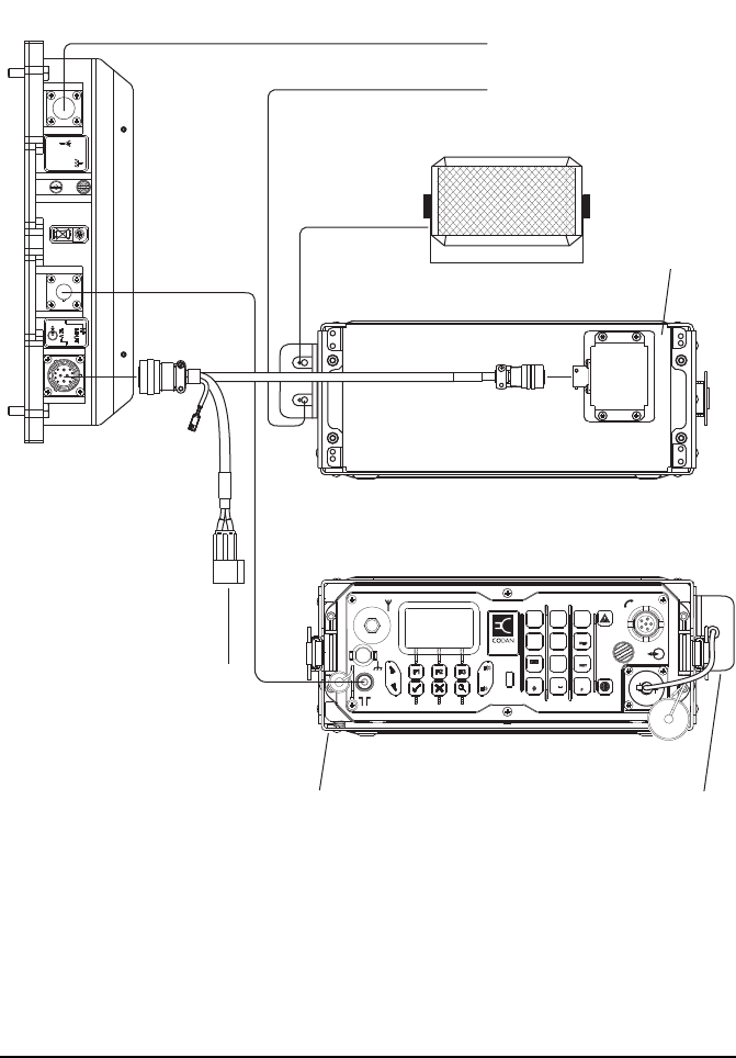
A 2110 amplifier adaptor panel (supplied with the 3160) is
attached to the rear of the 2110 cradle. When the manpack
transceiver is inserted into the cradle, it connects with the
2110 amplifier adaptor panel. A special power adaptor cable
connects the 2110 amplifier adaptor panel to the 3160 and an
appropriate 12 V DC power source. A coaxial cable connects
the antenna output from the connector on the front panel of
the transceiver to the RF INPUT connector on the 3160. The
RF output from the 3160 is sent to an antenna system via a
coaxial cable connected to the connector.
WARNING
In a mobile station, all items must be bolted
securely to rigid structures within the vehicle.
For more information on these requirements see
page 15, Installing the 3160.
NOTE For information on suitable power sources see
page 6, Power supply options.

Overview
Power Amplifier 3160 Installation Handbook 9
Basic layout
The basic layout is shown in Figure 5. It includes:
• a 2110M or 2110 Manpack Transceiver
• a 3160 Power Amplifier
• a 2110 series Manpack Transceiver cradle with interface
adaptor and external speaker
• a 2110 amplifier adaptor panel
• a power adaptor cable
• a coaxial cable
• a suitable 12 V DC supply
Overview
10 Power Amplifier 3160 Installation Handbook
Figure 5: Basic layout
Rear view of the transceiver
Front view of the transceiver
to 12 V DC
power supply
12V
to antenna (RF)
to antenna (control)
VIEW
0
1QZ
TUNE
2ABC
FUNC MODE
DEF
3
Rx
FREE
4GHI 5JKL
Tx
PWR
6
7PRS 8TUV
SEC GPS
9
CALL
LOGS
EASI
TALK
HOP
3160 Power Amplifier
08-06809-001
08-06808-002
external speaker
2110 cradle interface
adaptor
2110 amplifier
adaptor panel

Overview
Power Amplifier 3160 Installation Handbook 11
Stacked layout
The stacked layout is shown in Figure 6. It includes:
• a 2110M or 2110 Manpack Transceiver
• a 3160 Power Amplifier
• a 2110 series Manpack Transceiver cradle with interface
adaptor and external speaker
• a 2110 amplifier adaptor panel
• a power adaptor cable
• a coaxial cable
• a suitable 12 V DC supply
• a power amplifier mounting bracket (includes long
screws for attaching the interface adaptor to the cradle)
• a power supply cover (includes transceiver supply
brackets and various captive nuts, screws and washers)
(optional)
CAUTION
Please read the installation process before
assembling the stacked layout (see Figure 8 on
page 23).
Overview
12 Power Amplifier 3160 Installation Handbook
Figure 6: Stacked layout
to 12 V DC
power supply
to antenna
(RF)
to antenna
(control)
Front view of the stack
VIEW
0
1QZ
TUNE
2ABC
FUNC MODE
DEF
3
Rx
FREE
4GHI 5JKL
Tx
PWR
6
7PRS 8TUV
SEC GPS
9
CALL
LOGS
EASI
TALK
HOP
Rear view of the stack
12V
3160 Power
Amplifier
08-06809-002
08-06808-500
external speaker
2110
cradle
interface
adaptor
2110
amplifier
adaptor
panel
power
supply
cover
power
amplifier
mounting
bracket

Overview
Power Amplifier 3160 Installation Handbook 13
Care and safety guidelines
The following guidelines are intended for best performance of
the equipment and operator safety:
• Ensure that the 3160 and manpack transceiver are in a
well-ventilated area.
• Check the mounting points regularly if the installation is
subject to continuous vibration.
• Ensure that the installation is grounded to a suitable earth
point.
• Check the safe working distance for the type of antenna
you are using at 125 W output.

Overview
14 Power Amplifier 3160 Installation Handbook
Compatibility
The following hardware build standards are required for
operation with the 3160:
Both types of transceiver must have firmware V4.91 or later.
Upgrades are available for the hardware and firmware. Please
contact your Codan representative for more information.
Transceiver type Build standard
2110M Manpack Transceiver A or later
2110 Manpack Transceiver H or later
NOTE
The build standard is indicated by the 8th
character in the serial number of the transceiver.
The serial number is located under the bar code.

Power Amplifier 3160 Installation Handbook 15
2 Installing the 3160
This section contains the following topics:
Disclaimer (16)
What you need to consider (17)
Installing the 3160 in a basic layout (21)
Installing the 3160 in a stacked layout (22)
Attaching the 2110 amplifier adaptor panel to the rear of the
transceiver cradle (24)
Attaching the 3160, voltage regulator and external speaker to a
mounting surface (26)
Attaching a suitable power supply to the power supply
cover (27)
Attaching the power amplifier mounting bracket to the
transceiver cradle (27)
Attaching the 3160 and external speaker to the power
amplifier mounting bracket (31)
Connecting the equipment (33)
Setting up the transceiver (34)
Grounding the 3160 (34)
Installing the station (35)

Installing the 3160
16 Power Amplifier 3160 Installation Handbook
Disclaimer
WARNING
The 3160 Power Amplifier should be installed
by a suitably qualified technician, to the
relevant standards and approvals.
WARNING
While the following instructions are intended to
assist with installation, it is the purchaser’s
responsibility to ensure that the 3160 is installed
with due regard to vehicle-occupant safety,
particularly in the event of a vehicle accident.
Codan accepts no responsibility or liability in
the event of injury to vehicle occupants or any
other damage due to insecure or otherwise
unsafe or inappropriate installation of the 3160.

Installing the 3160
Power Amplifier 3160 Installation Handbook 17
What you need to consider
There are different requirements that must be considered,
depending on the layout and type of station in which the 3160
is used, that is, basic or stacked layout, mobile or fixed station.
Please read the sections that are relevant to your installation.
Basic layout
When installing the 3160 you must consider:
• the location and mounting of the 3160
• the routing of the coaxial and control cables
• grounding requirements for the 3160
The basic layout (see Figure 5 on page 10) is connected using
a 2 m power adaptor cable between the 2110 amplifier adaptor
panel (and hence the transceiver cradle) and the 3160.
Therefore, these items need to be located within 2 m of each
other. For dimensions of each item see page 37,
Specifications.
The fins on the heatsink of the 3160 should be oriented so that
warm air can move easily away from the fins. Ideal
orientations for the 3160 are shown in Figure 5 on page 10 and
Figure 6 on page 12.

Installing the 3160
18 Power Amplifier 3160 Installation Handbook
Stacked layout
The stacked layout (see Figure 6 on page 12) provides a
mounting system that connects all items together in a rugged
stack.
For overall dimensions of the stack see Figure 14 on page 39.
Mobile station
The 3160 should be mounted in a location that:
• is clear of surrounding body work
• does not interfere with car openings
• provides adequate air flow around the unit
The 3160 must have:
• a strong anchorage point
• a sound electrical connection to the vehicle chassis
For specific instructions on mounting a vehicle cradle see the
fitting instruction provided with the cradle.
CAUTION
The stacked layout must be assembled in a
specific order, as some holes become hidden
during the assembly process. For more
information see page 22, Installing the 3160 in
a stacked layout.
NOTE
The power supply cover is not required if the
system is powered from a 12 V DC vehicle
battery.

Installing the 3160
Power Amplifier 3160 Installation Handbook 19
Cabling in a vehicle
The coaxial cable between the antenna and the 3160 should be
installed as far as possible from other vehicle wiring,
especially high-voltage ignition wiring or the engine
management computer.
The cabling must be in a position that:
• is away from the driver’s feet
• is secured and concealed as much as possible
• ensures the control and coaxial cables are separated from
the DC power cable by at least 200 mm (8 in) (except
over short distances, for example, to pass through the
same hole in a bulkhead)
• is secured behind protective metalwork (only if the
cables run under the vehicle)
Keep cables in the engine compartment away from:
• heat, for example, exhaust, air-conditioning systems, and
water pipes
• oils and corrosive liquids, for example, engine oil,
battery fluid, and brake fluid
Protect all the cables from sharp edges and mechanical
abrasions. Cables that pass through body panels or internal
bulkheads must be protected by rubber grommets. Holes in the
bulkhead need only be large enough to allow the end of the
cable with the smaller connector to pass through. Removing a
connector should be a last resort.
CAUTION Removal of factory-fitted connectors may cause
cable or connector faults.
CAUTION
Crimp-style coaxial connectors are not suitable
for external locations because they are
susceptible to mechanical damage and are not
weatherproof.
NOTE Any cabling under carpet or floor mats should
be clear of foot traffic.

Installing the 3160
20 Power Amplifier 3160 Installation Handbook
Fixed station
There are no specific requirements for locating the transceiver
and 3160 in a fixed station.
Mounting
The installed 3160 should enable easy access to the
connectors. The 3160 should be positioned with the fins on the
heatsink pointing upwards (as in the stacked layout), or if
mounted on a vertical surface, with the fins on the heatsink
running vertically (see Figure 5 on page 10).
In a mobile station, attach all items of the 3160 system to
structural components of the vehicle.
Grounding
The 3160 Power Amplifier must be grounded using an earth
strap (08-04515-001). In a mobile station, this strap must be
connected to the vehicle chassis. For more information see
page 34, Grounding the 3160.
WARNING Do not attach any items to loose or plastic
panels in a vehicle.
Installing the 3160
Power Amplifier 3160 Installation Handbook 21
Installing the 3160 in a basic layout
The basic layout uses the transceiver cradle and 2110
amplifier adaptor panel, but does not use any mounting
brackets. For more information see Figure 5 on page 10.
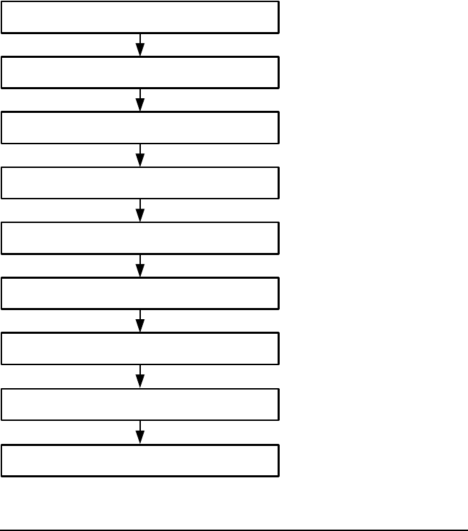
Figure 7: Process for installing the 3160 in a basic
layout
Attach the 2110 amplifier adaptor panel and
interface adaptor to the transceiver cradle
Attach the transceiver cradle to
an appropriate mounting surface
Insert the transceiver into the cradle,
then lock in place
Attach the 3160, voltage regulator (if used), and
external speaker to appropriate mounting surfaces
Connect the 2110 amplifier adaptor panel,
3160, and power supply together
Connect the interface adaptor to the transceiver
Connect the RF and control cables between the
transceiver, 3160, and antenna as required
Connect the external speaker to the interface adaptor
Ground the 3160
See page 24, Attaching the 2110
amplifier adaptor panel to the rear
of the transceiver cradle and the
fitting instruction provided with the
cradle
See page 26, Attaching the 3160,
voltage regulator and external
speaker to a mounting surface
See page 33, Connecting the
equipment
See page 34, Grounding the 3160

Installing the 3160
22 Power Amplifier 3160 Installation Handbook
Installing the 3160 in a stacked layout
The stacked layout uses a power amplifier mounting bracket
to attach the 3160 and external speaker to the transceiver
cradle. For more information see Figure 6 on page 12.
NOTE The rear of the transceiver cradle and the 3160
must be within 2 m of each other.
WARNING
If this layout is installed in a mobile station, all
items must be attached to appropriate mounting
surfaces according to the relevant standards and
approvals.
NOTE The power supply cover is not required if the
3160 is connected directly to a 12 V DC battery.
Installing the 3160
Power Amplifier 3160 Installation Handbook 23
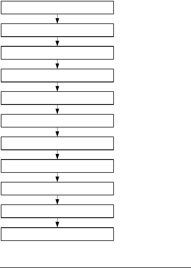
Figure 8: Process for installing the 3160 in a stacked
layout
Attach the 2110 amplifier adaptor panel to
the transceiver cradle
Attach the transceiver cradle to the power supply
cover (if used), or an appropriate mounting surface
Insert the transceiver into the cradle,
then lock in place
Attach the 3160 and external speaker to the
power amplifier mounting bracket
Connect the 2110 amplifier adaptor panel, 3160, and
power supply together
Attach the 3020 or voltage regulator to
the power supply cover (if used)
Attach the power amplifier mounting bracket and
the interface adaptor to the transceiver cradle
Connect the interface adaptor to the transceiver
Connect the RF and control cables between the
transceiver, 3160, and antenna as required
Connect the external speaker to the interface adaptor
Ground the 3160
See the fitting instruction provided
with the power supply cover
(15-00147-001)
See page 24, Attaching the 2110
amplifier adaptor panel to the rear
of the transceiver cradle
See page 27, Attaching the power
amplifier mounting bracket to the
transceiver cradle
See page 31, Attaching the 3160
and external speaker to the power
amplifier mounting bracket
See page 33, Connecting the
equipment
See page 34, Grounding the 3160
Installing the 3160
24 Power Amplifier 3160 Installation Handbook
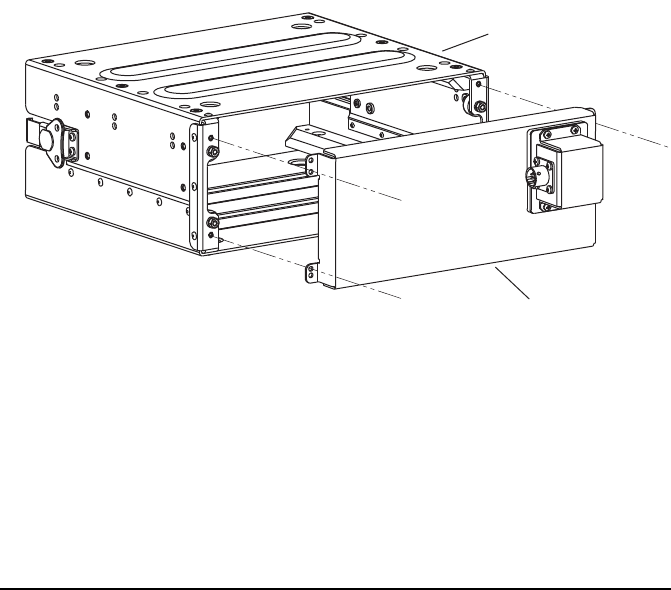
Attaching the 2110 amplifier adaptor panel
to the rear of the transceiver cradle
To attach the panel to the cradle:
1Place the cradle with the mounting domes facing down.
1Position the 2110 amplifier adaptor panel as shown in
Figure 9.
Figure 9: 2110 amplifier adaptor panel and cradle
1Attach the 2110 amplifier adaptor panel to the rear of the
cradle using the four M3 × 12 mm long, black, stainless
steel, pan pozi screws provided.
NOTE
If you are mounting the cradle in a basic
layout, orientate the cradle so that it meets
your requirements.
cradle with mounting
domes facing down
2110 amplifier
adaptor panel

Installing the 3160
Power Amplifier 3160 Installation Handbook 25
If you are using a... Continue from...
Basic layout Without power supply
cover
page 26, Attaching the 3160, voltage
regulator and external speaker to a
mounting surface
Stacked layout With power supply cover page 27, Attaching a suitable power
supply to the power supply cover
Without power supply
cover
page 27, Attaching the power
amplifier mounting bracket to the
transceiver cradle

Installing the 3160
26 Power Amplifier 3160 Installation Handbook
Attaching the 3160, voltage regulator and
external speaker to a mounting surface
To attach the 3160, voltage regulator, and speaker to a
mounting surface:
1Position the 3160 on a suitable mounting surface with the
fins either facing upwards or running vertically, and the
connectors easily accessible.
1Do one of the following:
• Attach the 3160 to the mounting surface using a
12AB × 25 mm long, self-tapping, pan pozi screw in
each of the holes in the flanges of the 3160.
• Attach the 3160 to the mounting structure using an
M6 × 25 mm long, stainless steel Hex screw with an
M6 stainless steel spring washer, and M6 stainless steel
hex nut in each of the holes in the flanges of the 3160.
1Attach the voltage regulator to a suitable mounting
surface using appropriate screws, washers, and nuts as
required.
1Attach the mounting cradle of the speaker to the
mounting surface with appropriate screws, washers, and
nuts as required.
1Attach the speaker to the mounting cradle with the two
thumb screws and rubber washers provided.
1Continue from page 33, Connecting the equipment.

Installing the 3160
Power Amplifier 3160 Installation Handbook 27
Attaching a suitable power supply to the
power supply cover
The power supply cover is an optional item of equipment that
is supplied with its own fitting instructions. For information
on power supply options see page 6, Power supply options.
Please read Fitting Instruction 15-00147-001 for information
on installing this item correctly.
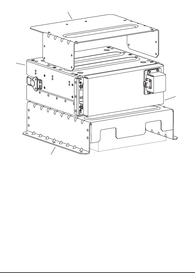
Attaching the power amplifier mounting
bracket to the transceiver cradle
To attach the mounting bracket to the cradle:
1Position the power amplifier mounting bracket over the
top of the transceiver cradle (see Figure 10).
NOTE
If the mobile station is connected directly to a
12 V DC vehicle battery, the power supply
cover is not required.
CAUTION
The transceiver cradle must be attached to the
power supply cover or a suitable mounting
structure before attaching the power amplifier
mounting bracket. When the mounting bracket
is in place, the access holes for mounting the
transceiver cradle are covered. For more
information see the fitting instructions provided
with the cradle and power supply cover.
WARNING All items must be mounted according to
relevant standards and approvals.
Installing the 3160
28 Power Amplifier 3160 Installation Handbook
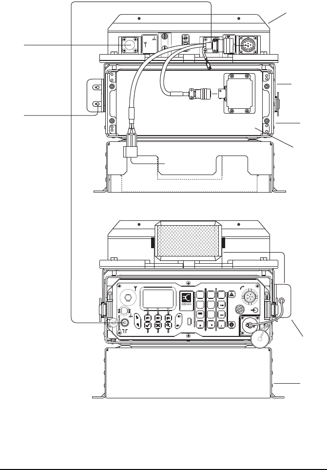
Figure 10: Power supply cover, cradle, and power
amplifier mounting bracket
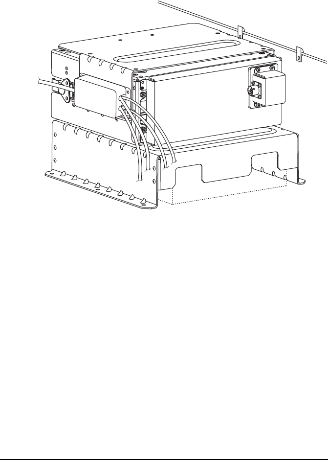
1Insert the coaxial cable (08-06809-002) into the two
P-clips provided.
1Position the interface adaptor on the side of the power
amplifier mounting bracket (see Figure 11).
power supply cover
2110
amplifier
adaptor
panel
power amplifier
mounting bracket
cradle
Installing the 3160
Power Amplifier 3160 Installation Handbook 29
Figure 11: Power supply cover, cradle, power amplifier
mounting bracket, interface adaptor, and coaxial cable
1Align the holes in the flanges of the interface adaptor
with the holes in the power amplifier mounting bracket
and the cradle.
1Insert an M4 × 12 mm long, black, stainless steel, pan
pozi screw into each of the holes for the interface adaptor
and power amplifier mounting bracket, then screw these
one turn into the transceiver cradle.
1On the other side of the cradle, insert an M4 × 12 mm
long, black, stainless steel, pan pozi screw into each of
the P-clips, passing these through the power amplifier
mounting bracket into the transceiver cradle.
NOTE Lift the mounting bracket to align the holes
with those on the transceiver cradle.

Installing the 3160
30 Power Amplifier 3160 Installation Handbook
1Insert an M4 × 8 mm long, black, stainless steel, pan pozi
screw into the remaining holes in the power amplifier
mounting bracket to attach it to the transceiver cradle.
1Tighten all screws.
Installing the 3160
Power Amplifier 3160 Installation Handbook 31
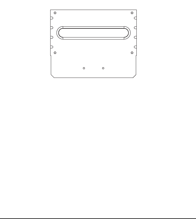
Attaching the 3160 and external speaker to
the power amplifier mounting bracket
The power amplifier mounting bracket has two sets of holes
drilled in the top.
Figure 12: Holes in the power amplifier mounting
bracket
To attach the 3160 and speaker to the bracket:
1Position the 3160 on top of the power amplifier
mounting bracket, with the connectors facing toward the
rear of the transceiver cradle (see Figure 13).
Rear
Front
power
amplifier
power
amplifier
power
amplifier
power
amplifier
external
speaker
external
speaker
Installing the 3160
32 Power Amplifier 3160 Installation Handbook
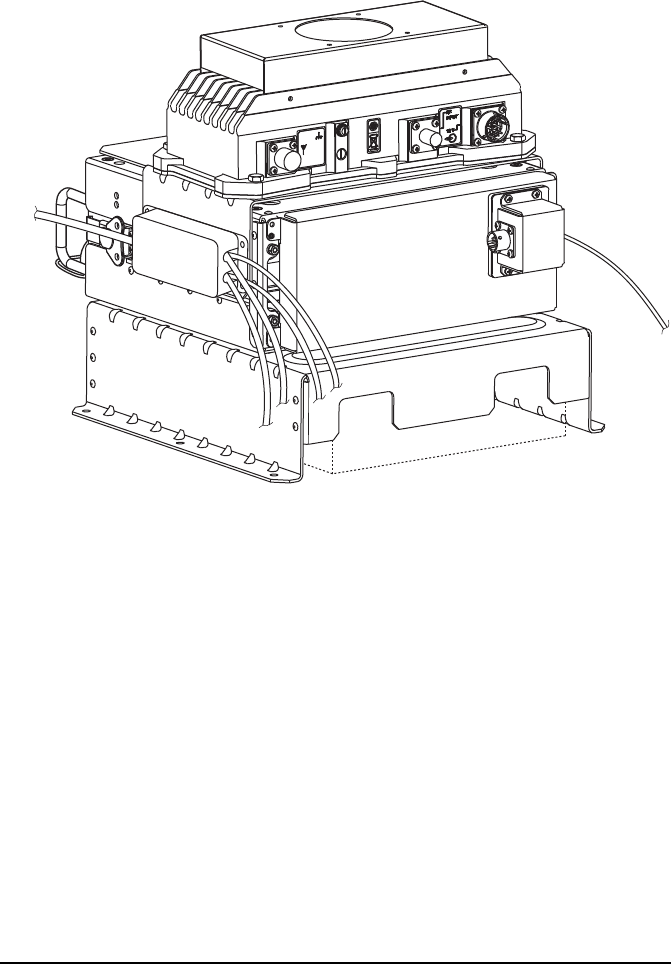
Figure 13: 3160 and power amplifier mounting bracket
1Attach the 3160 to the bracket using an M5 × 20 mm
long, black, stainless steel, pan pozi screw through each
hole in the flanges of the 3160 into the captive nut in the
bracket.
1Attach the mounting cradle of the speaker to the power
amplifier mounting bracket using an M4 × 6 mm long,
stainless steel, pan pozi screw through each hole in the
cradle into the captive nut in the bracket.
1Attach the speaker to the mounting cradle with the two
thumb screws and rubber washers provided.

Installing the 3160
Power Amplifier 3160 Installation Handbook 33
Connecting the equipment
The equipment is connected the same, regardless of the layout
that is used. The length of each cable used may vary
depending on the layout. See Figure 5 on page 10 and
Figure 6 on page 12 for more information.
To connect the equipment:
1Connect the 12-way connector on the power adaptor
cable (08-06808-xxx) to the 12 V connector on the 3160.
1Connect the 6-way connector on the power adaptor cable
to the connector on the 2110 amplifier adaptor panel.
1Connect the BNC–BNC coaxial cable (08-06809-xxx)
between the connector on the front panel of the
transceiver and the RF INPUT connector on the 3160.
1Connect the 12 V connector on the power adaptor cable
to a suitable 12 V DC supply (see page 6, Power supply
options).
1Connect a coaxial cable between the connector on the
3160 and the appropriate connector on the antenna.
1Connect the antenna control cable between the lead
from the interface adaptor and the appropriate connector
on the antenna or antenna tuner, if required.
Installing the 3160
34 Power Amplifier 3160 Installation Handbook
Setting up the transceiver
To set up the transceiver for operation with the 3160:
1Go to the Cfg Auto Tune Mode entry in the Control List.
1Do one of the following:
• If the transceiver is installed permanently with the
3160, set the Cfg Auto Tune Mode entry to
50 Ohm.
• If the transceiver is installed for jerk-and-run
capability, set the Cfg Auto Tune Mode entry to
ATU/ 50/ Codan.
1Switch the transceiver off then on again to activate the
change.
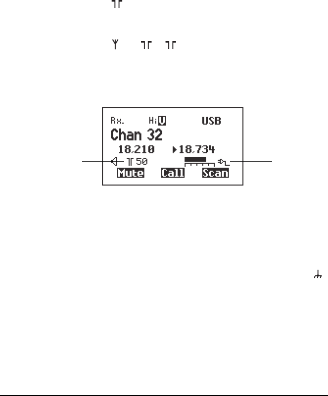
The screen should look similar to the following.
Grounding the 3160
To ground the 3160:
1Attach one end of the earth wire to the earth terminal ( )
on the connector panel of the 3160.
1Attach the other end of the earth wire to the earth system
for the station using the 25 mm long, self-tapping, pan
pozi screw provided.
antenna external power
supply indicator
selection
icon

Installing the 3160
Power Amplifier 3160 Installation Handbook 35
Installing the station
To install the 3160 in a mobile or fixed station:
1Attach the transceiver cradle or the power supply cover
to an appropriate mounting surface according to any
relevant standards and approvals.
1Connect an earth strap to a convenient location on the
bodywork or earth system for the building using the
25 mm long, self-tapping, pan pozi screw provided.
1Connect the antenna to the transceiver (see the fitting
instructions provided with the mounting cradle and or
equipment).
1Protect any cables that pass through metal panels with
rubber grommets.
1Tape the connectors on the antenna, and approximately
25 mm (1 in) of each cable, with two layers of self-
amalgamating PIB tape (Rotunda 2501) or EPR tape (3M
Scotch™ 23).
1Cover the self-amalgamating tape with two layers of
high-quality electrical tape (3M Scotch™ 33+, or
similar) to minimise aging of the self-amalgamating tape.
1Test the installed 3160 (with connected transceiver) as
described in the Reference Manual provided with your
transceiver.
NOTE In a mobile station, you may need to use a
mounting setup that absorbs vibration.
NOTE Ensure a good electrical connection is
made.
NOTE
Troubleshooting for a 3160 and how to
install a transceiver are provided in the
Reference Manual.

Installing the 3160
36 Power Amplifier 3160 Installation Handbook
This page has been left blank intentionally.

Power Amplifier 3160 Installation Handbook 37
3 Specifications
These specifications are accurate for a 13.6 V DC supply, with
50 Ω load resistances at 25°C (77°F).
Table 1: Functional specifications
Item Specification
Frequency range 1.6 to 30 MHz
Power output 125/100 W PEP reducing with frequency to 95 W PEP at
30 MHz ±1dB
CW or single tone: approximately 60% of PEP with average
PEP control (average control disabled on handset PTT)
Spurious and
harmonic emissions
Better than 60 dB below PEP
Intermodulation
(Two-tone test)
125/100 W: 26 dB below each tone 32 dB below
PEP
RF input/output
impedance
50 Ω nominal
Duty cycle 100%: normal speech over full temperature
range
100%: ARQ up to 30°C (86°F)
25%: 16-tone continuous data mode
(5 minutes on maximum) at ambient
temperature up to 30°C (86°F)
100%: all data modes up to maximum ambient
temperature of 45°C (113°F) with
Option F
Supply voltage 13.6 V DC nominal, negative earth
Normal operating
range:
10.8 to 15 V
Reverse polarity protected

Specifications
38 Power Amplifier 3160 Installation Handbook
Overvoltage
protection
Shuts down at 16 V ±0.5 V DC nominal for duration of
overvoltage
Supply current Output power: 125 W or 100 W
Two-tone or CW: 9 to 17 A
Average speech: 8 A for battery life calculations
Receive: 65 mA
Protection Safe under all load conditions by limiting reflected power to
10 W PEP and limiting PA transistor collector voltage swing
Thermal protection against excessive heatsink temperature
Environment Ambient
temperature:
–30 to 60°C
(–22 to 140°F)
Relative humidity: 95% non-condensing
Derate upper ambient temperature by 1°C (33.8°F) per 330 m
(361 yd) above sea level.
MIL-STD-810F compliance:
Method 500.4: Low Pressure (Altitude)
Method 506.4: Rain
Method 507.4: Humidity
Method 508.5: Fungus
Method 509.4: Salt Fog
Method 510.4: Sand and Dust
Method 512.4: Immersion (IP68: immersion for 1 hour at a
depth of 1 m (3 ft))
Method 514.5: Vibration
Method 516.5: Shock
Cooling Convection or fan (option F)
Mounting Free standing
Flange mounting (power supply cover)
Enclosed mounting (transceiver cradle)
Table 1: Functional specifications (cont.)
Item Specification
Specifications
Power Amplifier 3160 Installation Handbook 39
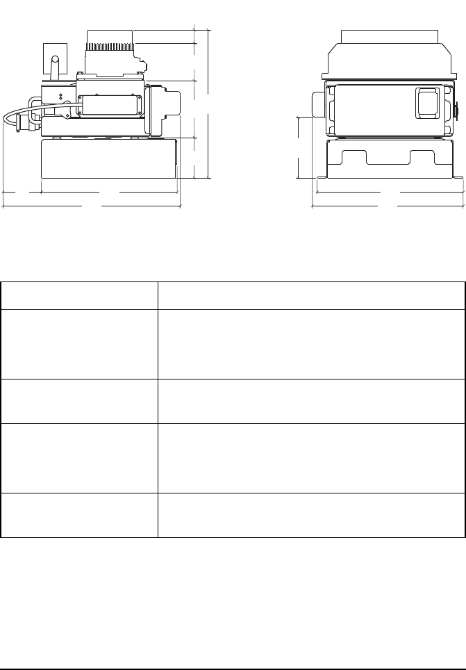
Figure 14: Dimensions
Table 2: Dimensions
Item Size
Power amplifier 286 mm W × 146 mm D × 77 mm H
(11.3inW × 5.7inD × 3.0inH)
(includes allowance for connectors)
Power amplifier with fan 286 mm W × 146 mm D × 106 mm H
(11.3inW × 5.7inD × 4.1inH)
Transceiver in cradle with
interface adaptor and 2110
amplifier adaptor panel
307 mm W × 372 mm D × 112 mm H
(12.1inW × 14.6inD × 4.4inH)
(includes allowance for connectors)
Power supply cover 304 mm W × 282 mm D × 83 mm H
(12.0inW × 11.1inD × 3.3inH)
80 282
372
85 119 77 29
310
Side view
317
304
121
Rear view
All dimensions in mm

Specifications
40 Power Amplifier 3160 Installation Handbook
Table 3: Weights for accessories
Item Weight
Power amplifier 2.2 kg
(4.9 lb)
2110 amplifier adaptor
panel
0.3 kg
(0.7 lb)
Fan 0.3 kg
(0.7 lb)
Power amplifier mounting
bracket
0.5 kg
(1.1 lb)
Power supply cover,
including brackets
1.0 kg
(2.2 lb)
Power Amplifier 3160 Installation Handbook 41
4 Accessories
Table 4: Accessories for the 3160 Power Amplifier
Codan part
number
Description
15-00147 Power supply cover
15-00148 Power amplifier mounting bracket
08-06900-001 Fan
08-06808-500 Cable, control and power, 0.5 m
08-06808-002 Cable, control and power, 2 m
08-06809-002 Cable, coaxial, 0.7 m
08-06809-001 Cable, coaxial, 2.5 m

Accessories
42 Power Amplifier 3160 Installation Handbook
This page has been left blank intentionally.
Power Amplifier 3160 Installation Handbook 43
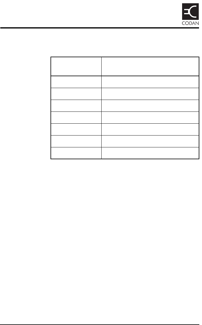
Appendix A—Connectors
Figure 15: Front view of the 12-way connector on the
3160
Table 5: Pinouts for the 12-way connector on the 3160
Pin no. Function Input/output Signal level
A ALC Output 3.5 V = ALC control
B Fan (–) switched Output 0 V
C DC supply ground (–) Input 0 V
D Fan (+) Output 13.6 V nominal
EI
2C clock Input 3.3 V data
FI
2C data Input/output 3.3 V data
G DC supply positive (+) Input 13.6 V nominal
H Screen ground Input 0 V
J DC supply positive (+) Input 13.6 V nominal
K DC supply ground (–) Input 0 V
L DC supply ground (–) Input 0 V
M DC supply positive (+) Input 13.6 V nominal
A
B
C
DE
F
G
H
J
K
L
M
Connectors
44 Power Amplifier 3160 Installation Handbook
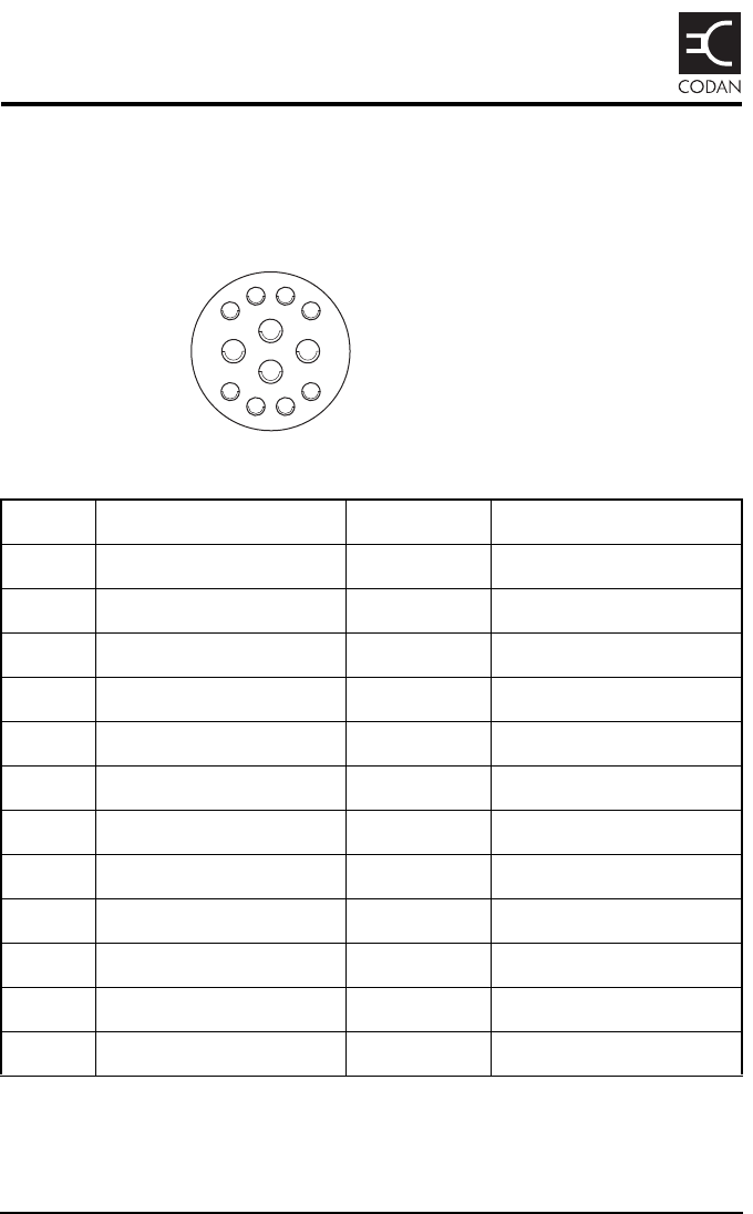
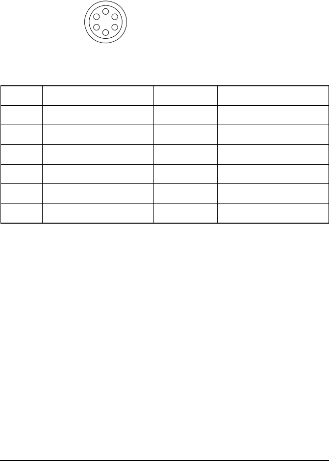
Figure 16: Front view of the 6-way connector on the
2110 amplifier adaptor panel
Table 6: Pinouts for the 6-way connector on the 2110
amplifier adaptor panel
Pin no. Function Input/output Signal level
A Screen ground Input 0 V
B DC supply ground (–) Input 0 V
CI
2C clock Input 3.3 V data
DI
2C data Input/output 3.3 V data
E ALC Output 3.5 V = ALC control
F DC supply positive (+) Input 13.6 V nominal
A
F
E
D
C
B


Compliance
46 Power Amplifier 3160 Installation Handbook
Introduction
This section describes how to ensure the 3160 Power
Amplifier complies with the European EMC Directive 89/336/
EEC and the European Low Voltage Directive 73/23/EEC as
called up in the European R&TTE Directive 1999/5/EC.
This section also contains the requirements for FCC
compliance.
European R&TTE Directive
The 3160 Power Amplifier has been tested and complies with
the following standards and requirements (articles of the
R&TTE Directive):
• Article 3.1b: ETSI EN301489-1 V1.4.1
• Article 3.1b: ETSI EN301489-15 V1.2.1
• Article 3.1a: EN60950-1
Product marking and labelling
Any equipment supplied by Codan that satisfies these
requirements is identified by the , , or
markings on the model label of the product.
Declaration of Conformity
The CE Declaration of Conformity for the product is listed on
page 60, Associated documents. This document can be made
available upon request to Codan or a Codan-authorised
supplier.
0191
0191

Compliance
Power Amplifier 3160 Installation Handbook 47
EMC and safety notices
Non-ionising radiation safety
To ensure optimal transceiver performance and to avoid
exposure to excessive electromagnetic fields, the antenna
system must be installed according to the instructions
provided.
Safe working distance is based on continuous exposure to
CW-type transmissions, as set out in the ICNIRP Exposure
Guidelines (1998) for occupational exposure. Safe working
distance can be reduced with normal voice communication.
WARNING
High voltages exist on the antenna during
transmission and tuning. Do not touch the
antenna during these activities. RF burns may
result.
WARNING
Install the earthing system or counterpoise as
directed to prevent RF burns from any metal
part of the transceiver.
WARNING
You should not transmit from your transceiver
or tune the antenna unless people are beyond the
safe working distance of:
• 1.5 m (5 ft) of any part of a mobile antenna
• 2 m (7 ft) of any part of a fixed antenna in a
data installation of up to 125 W output

Compliance
48 Power Amplifier 3160 Installation Handbook
EMC
To ensure compliance with the EMC Directive is maintained,
you must:
1Use the standard shielded cables supplied from Codan
(where applicable).
Electrical safety
To ensure compliance with the European Low Voltage
Directive is maintained, you must install the 3160 Power
Amplifier in accordance with the instructions in this
handbook, and operate the 3160 Power Amplifier in
accordance with the instructions in the relevant Getting
Started Guide and Reference Manual for your transceiver.
C-tick approval
The 3160 Power Amplifier meets the requirements of the
Australian Communications and Media Authority:
Radiocommunications (MF and HF equipment—Land Mobile
Service) Standards 2003 (AS/NZS 4470).

Compliance
Power Amplifier 3160 Installation Handbook 49
FCC compliance
FCC Part 90 certification
The 3160 Power Amplifier has been tested and certified to
FCC Part 90 (FCC identifier code DYY3160).
FCC Part 15 compliance
Any modifications made to the 3160 Power Amplifier that are
not approved by the party responsible for compliance may
void your equipment’s compliance under Part 15 of the FCC
rules.
The 3160 Power Amplifier has been tested and found to
comply with the limits for a Class B device, pursuant to
Part 15 of the FCC rules. These limits are designed to provide
reasonable protection against harmful interference in a
residential installation. This equipment generates, uses and
can radiate radio frequency energy and, if not installed and
used in accordance with the instructions, may cause harmful
interference to radio communications. However, there is no
guarantee that interference will not occur in a particular
installation. If this equipment does cause harmful interference
to radio or television reception, which can be determined by
switching the equipment off and on, the user is encouraged to
try to correct the interference by one or more of the following
measures:
• reorient or relocate the receiving antenna
• increase the separation between the equipment and
receiver
• connect the equipment into an outlet on a circuit different
from that to which the receiver is connected
• consult the dealer or an experienced radio/TV technician
for help

Compliance
50 Power Amplifier 3160 Installation Handbook
Compliance with RF exposure standards
Your Codan HF transceiver system is designed and tested to
comply with a number of national and international standards
and guidelines (listed below) regarding human exposure to RF
electromagnetic energy. This transceiver system complies with
the IEEE and ICNIRP exposure limits for occupational/
controlled RF exposure environments at duty factors of up to
50% talk (100% listen), and is authorised by the FCC for
occupational use.
Your Codan HF transceiver system complies with the
following RF energy exposure standards and guidelines:
• United States Federal Communications Commission,
Code of Federal Regulations; 47 CFR§§ 2 sub-part J
• American National Standards Institute/Institute of
Electrical and Electronic Engineers C95.1–1992
• Institute of Electrical and Electronic Engineers C95.1–
1999 Edition
Operating instructions to control RF exposure
To control exposure of yourself and others and ensure
compliance with the occupational/controlled environment
exposure limits, always adhere to the following procedures:
• Transmit no more than the rated duty factor of 50% of
the time, and remain at least 1.5 m from the antenna.
• Do not transmit from the transceiver or tune the antenna
unless people outside the vehicle are beyond the safe
operating distance of 1.5 m (5 ft) of any part of a mobile
antenna.

Compliance
Power Amplifier 3160 Installation Handbook 51
Mobile antennas
The antenna installation should be in accordance with the
supplied installation handbook. Use only Codan’s approved
supplied antenna.
Approved accessories
The Codan HF transceiver system has been tested and meets
the FCC RF exposure guidelines when used with the Codan
accessories supplied or designated for this product. Use of
other accessories may not ensure compliance with the FCC’s
RF exposure guidelines, and may violate FCC regulations.
Contact information
For additional information on exposure requirements or other
information, see Codan’s website (www.codan.com.au).

Compliance
52 Power Amplifier 3160 Installation Handbook
IC approval
The 3160 Power Amplifier meets the requirements of
RSS-131.
The following information is relevant for the 3160 Power
Amplifier:
The manufacturer’s rated output power of this equipment is
for single carrier operation. For situations when multiple
carrier signals are present, the rating would have to be reduced
by 3.5 dB, especially where the output signal is re-radiated
and can cause interference to adjacent band users. This power
reduction is to be by means of input power or gain reduction
and not by an attenuator at the output of the device.
Nominal passband gain 10 dB
Nominal bandwidth 28.4 MHz
Rated mean output power 125 W
Input/output impedance 50 Ω

Compliance
Power Amplifier 3160 Installation Handbook 53
Register of hazardous substances
Table 7: 有毒有害物质列表 (Register of hazardous
substances)
零件项目
(Component Name)
有毒有害物质或元素
(Hazardous Substances or Elements)
3160 功率放大器
(3160 Power Amplifier)
铅
汞
镉
六价鉻
多溴联苯
多溴二苯醚
3160 主体装配
(3160 Main Assembly)
XOOOOO
控制电缆
(Control Cable)
OOOOOO
同轴电缆
(Coaxial Cable)
OOOOOO
接地线 08-04515-001
(Earth Wire 08-04515-001)
OOOOOO
功率放大器 3160 安装手册
(Power Amplifier 3160 Installation
Handbook)
OOOOOO

Compliance
54 Power Amplifier 3160 Installation Handbook
O表示该有毒有害物质在该部件的所有均质材料中的含量 , 均在 SJ/T
11363-2006 标准所规定的限量要求以下 .
Indicates that this toxic or hazardous substance, contained in all of the
homogeneous materials for this part, is below the limit requirement in SJ/
T 11363-2006.
X表示该有毒有害物质在该部件的至少一种均质材料中的含量 , 超出
SJ/T 11363-2006 标准所规定的限量要求 .
Indicates that this toxic or hazardous substance, contained in at least one of
the homogeneous materials used for this part, is above the limit requirement
in SJ/T 11363-2006.
怎么阅读制造日期 - 方法如下 :
How to read the date of manufacture:
产品序列号中的第一个数字或字母表示该产品在 2000 年或以后的制造年份 .
举例来说 ( 数字 0-9) 0=2000, 1=2001... 之后接着以字母代表制造年份
A=2010, B=2011...
The first character of the serial number provides the year of manufacture starting
from the year 2000, that is, 0=2000, 1=2001...A=2010, B=2011...
产品序列号中的第二个数字或字母表示该产品的制造月份 . 举例来说 ( 数字
1-9) 1= 一月份 , 2= 二月份 ... 之后接着以字母 A,B,C 代表剩下的制造月
份 A= 十月份 , B= 十一月份 ,C= 十二月份 .
The second character of the serial number provides the month of manufacture, that
is, 1 to 9, A to C; A=10th month, B=11th month and C= 12th month.

Power Amplifier 3160 Installation Handbook 55
Appendix C—Definitions
Standards and icons
The following standards and icons are used in this handbook:
This typeface Means...
Italic a cross-reference or text requiring emphasis
This icon Means...
a step within a task
NOTE the text provided next to this icon may be of
interest to you
CAUTION proceed with caution as your actions may
lead to loss of data, privacy or signal quality
WARNING your actions may cause harm to yourself or
the equipment

Definitions
56 Power Amplifier 3160 Installation Handbook
Acronyms and abbreviations
This term... Means...
ANSI American National Standards Institute
CW continuous wave
DC direct current
EPR ethylene propylene rubber
ETSI European Telecommunications Standards
Institute
FCC Federal Communications Commission
HF high frequency
ICNIRP International Commission on Non-Ionizing
Radiation Protection
IEEE Institute of Electrical and Electronic
Engineers
PIB poly isobutylene
R&TTE radio and telecommunications terminal
equipment
RF radio frequency

Definitions
Power Amplifier 3160 Installation Handbook 57
Glossary
This term... Means...
fixed station A transceiver that is permanently installed
and cannot be moved without significant
effort. It consists of a transceiver, a
transceiver supply, an antenna, control and
accessory devices, a 3160, ancillary
equipment, and appropriate connecting
cables.
mobile station A station that is usually mounted in a
vehicle or is portable and easily
transportable. It consists of a transceiver, a
power supply, an antenna, control and
accessory devices, a 3160, ancillary
equipment, and appropriate connecting
cables.
basic layout The layout of the manpack transceiver and
3160 without frames and brackets.
stacked layout The layout of the manpack transceiver and
3160 with various frames and brackets.

Definitions
58 Power Amplifier 3160 Installation Handbook
Units
NOTE Imperial dimensions are in United States
Customary Units.
Measurement Unit Abbreviation
Current ampere A
Frequency hertz Hz
Impedance ohm Ω
Length metre
(inch/feet)
m
(in/ft)
Power watt W
Power ratio decibel dB
Temperature degrees Celsius
(Fahrenheit)
°C
(°F)
Voltage volt V
Weight gram
(pound)
g
(lb)

Definitions
Power Amplifier 3160 Installation Handbook 59
Unit multipliers
NOTE
Units are expressed in accordance with ISO
1000:1992 ‘SI units and recommendations for
the use of their multiples and of certain other
units’.
Unit Name Multiplier
M mega 1000000
d deci 0.1
m milli 0.001

Definitions
60 Power Amplifier 3160 Installation Handbook
About this issue
This is the second issue of the Power Amplifier 3160
Installation Handbook. Requirements for FCC compliance and
IC approval have been added.
Associated documents
This handbook is one of a series of documents associated with
the 3160 Power Amplifier. The other documents are:
• Manpack Transceiver 2110M Getting Started Guide
(Codan part number 15-04152-EN)
• Manpack Transceiver 2110M Reference Manual (Codan
part number 15-04153-EN)
• Manpack Transceiver 2110 series Getting Started Guide
(Codan part number 15-04136-EN)
• Manpack Transceiver 2110 series Reference Manual
(Codan part number 15-04135-EN)
• Fitting Instruction: 2110 Manpack Transceiver cradle
15-00140 (c/w interface adaptor) (Codan part number
15-00140-001)
• Fitting Instruction: Power supply cover for 2110
Manpack Transceiver 15-00147 (Codan part number
15-00147-001)
• Declaration of Conformity for the 3160 Power Amplifier
(Codan part number 19-40330)

Power Amplifier 3160 Installation Handbook Index-1
Index
Numerics
3160
components 5
mounting cradle 20
B
basic layout 17
C
cabling 19
care and safety instructions 13
compliance
C-tick 48
EMC and safety notices 47
electrical safety 48
EMC 48
radiation safety 47
FCC 49
approved accessories 51
contact information 51
mobile antennas 51
Part 15 compliance 49
Part 90 certification 49
RF exposure
controlling 50
standards 50
IC 52
R&TTE Directive 46
declaration of conformity 46
product marking and labelling 46
connecting equipment 33
connectors 43
C-tick approval 48
E
EMC and safety notices
compliance
electrical safety 48
EMC 48
radiation safety 47
equipment
optional 5
typical 5
F
FCC compliance 49
approved accessories 51
contact information 51
mobile antennas 51
Part 15 compliance 49
Part 90 certification 49
RF exposure
controlling 50
standards 50
fixed station 20
G
grounding 20, 34
H
hazardous substances 53
I
IC approval 52
installation 15
2110 amplifier adaptor panel 24
3160 26, 31
basic layout 17, 21
cabling 19
external speaker 26, 31
fixed station 20
grounding 20
mobile station 18
mounting 20
power amplifier mounting bracket 27, 31
power supply 27
stacked layout 18, 22
transceiver cradle 24, 27
voltage regulator 26

Index
Index-2 Power Amplifier 3160 Installation Handbook
L
layout
basic 17, 21
stacked 18, 22
M
mobile station 18
mounting cradle 20
O
optional equipment 5
overview 3
R
R&TTE Directive
compliance 46
declaration of conformity 46
product marking and labelling 46
S
safety
electrical 48
radiation 47
specifications 37
stacked layout 18
station
fixed 20
installing 35
mobile 18
T
transceiver
setting up 34
typical equipment 5

www.codan.com.au
Head Office
Codan Limited
ABN 77 007 590 605
81 Graves Street
Newton SA 5074
AUSTRALIA
Telephone +61 8 8305 0311
Facsimile +61 8 8305 0411
asiasales@codan.com.au
Codan (UK) Ltd
Unit C4 Endeavour Place
Coxbridge Business Park
Farnham Surrey GU10 5EH
UNITED KINGDOM
Telephone +44 1252 717 272
Facsimile +44 1252 717 337
uksales@codan.com.au
Codan US, Inc.
8430 Kao Circle
Manassas VA 20110
USA
Telephone +1 703 361 2721
Facsimile +1 703 361 3812
ussales@codan.com.au