Codan TG 003 1 0 Radio Basics Training Guide Guide2
User Manual: Codan User, Training and Maintenance Guides | LMR & HF Radio | Codan Radio
Open the PDF directly: View PDF ![]() .
.
Page Count: 82
www.codanradio.com
Radio System Basics
and RF Fundamentals
TRAINING GUIDE

RADIO SYSTEM BASICS & RF FUNDAMENTALS | TRAINING GUIDE
Page i
Radio System
Basics and RF
Fundamentals
Training Guide

TRAINING GUIDE | RADIO SYSTEM BASICS & RF FUNDAMENTALS
Page ii
Codan Radio Communications
43 Erie Street, Victoria, BC
Canada V8V 1P8
www.codanradio.com
LMRsales@codanradio.com
Toll Free Canada and USA:
Phone: 1-800-664-4066
Fax: 1-877-750-0004
International:
Phone: 250-382-8268
Fax: 250-382-6139
PRINTED IN CANADA
Documentation uses a three-level revision system. Each element of
the revision number signifi es the scope of change as described in the
diagram below.
Major Revisions:
The result of a major change to
product function, process or requirements.
Minor Revisions:
The result of a minor change to
product, process or requirements.
Editorial Revisions:
The result of typing corrections or
changes in formatting, grammar or wording.
1-0-0
Three-level revision numbers start at 1-0-0 for the fi rst release. The
appropriate element of the revision number is incremented by 1 for each
subsequent revision, causing any digits to the right to be reset to 0.
For example:
If the current revision = 2-1-1 Then the next major revision = 3-0-0
If the current revision = 4-3-1 Then the next minor revision = 4-4-0
If the current revision = 3-2-2 Then the next editorial revision = 3-2-3
Document revision history is provided at the back of the document.
© 2016 Codan Limited.
No part of this guide may be reproduced, transcribed, translated into any
language or transmitted in any form whatsoever without the prior written
consent of Codan Limited.
CODAN™, NGT™, Easitalk™, CIB™ and CALM™ are trademarks of
Codan Limited. Other brand, product, and company names mentioned
in this document are trademarks or registered trademarks of their
respective holders.
IMBE™ and AMBE+2™ are trademarks of Digital Voice Systems, Inc.
EDACS® is a registered trademark of M/A-COM, Inc.
The English version takes precedence over any translated versions.
NOTE
DOCUMENT REVISION
DEFINITION
Document Number:
Revision:
Revision Date:
TG-003
1-0-0
August 2016

RADIO SYSTEM BASICS & RF FUNDAMENTALS | TRAINING GUIDE
Page iii
Przemek Mroz is a professional engineer registered with the
Professional Engineers and Geoscientists of British Columbia
(P.Eng) , has a Bachelor’s Degree in Electrical Engineering from
the University of Victoria (B.Eng), and a Diploma in Electronics
Engineering Technology from the Southern Alberta Institute of
Technology. Przemek has been with Daniels / Codan since 2003,
and has worked in a variety of roles including manufacturing,
engineering and sales.
Pete Lunness is a member of the Applied Science Technologists
& Technicians of British Columbia, has a Diploma in Electronics
Engineering Technology from Camosun College and a Certifi cate in
Adult and Continuing Education from the University of Victoria. Pete
has been at Daniels / Codan since 1996, working in engineering,
sales and customer support, and has been instructing technical
training courses since 1998.
ABOUT THE AUTHORS
Codan Radio Communications is a leading international designer
and manufacturer of premium communications equipment for High
Frequency (HF) and Land Mobile Radio (LMR) applications. We’ve
built our reputation for reliability and customer satisfaction over 50
years in radio communications, in some of the toughest conditions
on the planet.
For over 50 years Codan has provided customers in North America
and internationally with highly reliable Base Stations and Repeaters
that are environmentally robust to operate in rugged and extreme
temperature conditions where low current consumption (solar
powered) is a key requirement.Codan is a pioneering member of
the P25 Digital standard, for radio system interoperability between
emergency response governmental organizations, providing
enhanced functionality and encryption. Our products operate
between 29 - 960 MHz and are available in a variety of Base Station
and Repeater confi gurations for two way voice and mobile data
applications.
Our self-servicing customers range from Forestry and National Park
services through Police and Fire departments and on to Utility and
Transportation groups. Our products have been deployed in every
imaginable situation from the Antarctic to Hawaiian mountaintops to
Alaska, enabling respondents to Forest Fires, Ground Zero rescue
and routine patrols. Codan is an industry leader in Analog and
P25 radio systems design. We offer modular rack-mounted Base
Stations and Repeaters capable of operating in VHF, UHF, 700 MHz,
800 MHz, and 900 MHz
ABOUT CODAN RADIO
COMMUNICATIONS
On August 7th, 2012 - Codan Limited (ASX: “CDA”) announced
the acquisition of Daniels Electronics Limited, a leading designer,
manufacturer and supplier of land mobile radio communications
(LMR) solutions in North America. The acquisition of Daniels delivers
on Codan’s stated strategy of growing market share and diversifying
its radio communications product offering. Codan Limited designs,
manufactures and markets a diversifi ed range of high value added
electronic products, with three key business divisions; radio
communications, metal detection and mining technology.
DANIELS ELECTRONICS
IS NOW CODAN RADIO
COMMUNICATIONS

TRAINING GUIDE | RADIO SYSTEM BASICS & RF FUNDAMENTALS
Page iv
Codan Radio Communications provides many resources for the
testing, tuning, maintenance and design of your Codan MT-4E
Analog and P25 Digital Radio System.
Instruction Manuals
Codan instruction manuals are very comprehensive and include
information on:
Theory of operation
Detailed Specifi cations
Testing and tuning instructions
Component layout illustrations
Instruction manuals can be obtained from the factory.
Technical Notes
Technical notes outline key aspects of tuning, installing,
maintaining and servicing Codan Radio Systems.
Technical Notes can be found online at www.codanradio.com.
Application Notes
Application Notes provide an overview of the range of applications
in which Codan Radio systems can be used.
Application Notes can be found online at www.codanradio.com.
P25 Training Guide
The P25 Training Guide provides the reader with a simple, concise
and informative description of Project 25.
The P25 Training Guide can be found online at
www.codanradio.com.
MT-4E Analog and P25 Digital Radio Systems User Guide
The MT-4E User Guide provides an overview of the confi guration,
operation and programming of Codan MT-4E radios.
The MT-4E User Guide can be found online at www.codanradio.com.
MT-4E Analog and P25 Digital Radio Systems Maintenance Guide
The MT-4E Maintenance Guide is an aid to confi guring and testing
Codan MT-4E radios using an IFR 2975 Service Monitor by
Aerofl ex. The Guide is intended to be used with IFR 2975 Setup
fi les that can be loaded into the Service Monitor.
The MT-4E Maintenance Guide can be found online at
www.codanradio.com
RESOURCES

RADIO SYSTEM BASICS & RF FUNDAMENTALS | TRAINING GUIDE
Page v
Contents
Chapter 1: Introduction ..........................................................1
Scope and Recommended Order of Reading ............................................1
Pre-Requisite Technical Knowledge...........................................................2
Land Mobile Radio ...........................................................................................2
Electricity and Magnetism ................................................................................2
Basic Electronic Elements ...............................................................................5
Mathematical Representations ..................................................................7
Graphs .............................................................................................................7
Mathematical Notation .....................................................................................8
Decibels ...........................................................................................................9
A Note About Radio Terminology ...................................................................10
Introduction to Regulatory Bodies .................................................................10
Chapter 2: Basic Radio Elements .........................................11
The Concept of Radio Communications .................................................. 11
The Nature of Electromagnetic Signals ................................................... 11
Electromagnetic Energy ................................................................................11
Amplitude, Frequency and Power .................................................................12
Electromagnetic Spectrum, Channels and Bandwidth ............................. 15
The Electromagnetic Spectrum .....................................................................15
Channels .......................................................................................................16
Frequency Bandwidth ....................................................................................17
A Simple Radio Communication System ................................................. 18
Source Information ................................................................................... 19
Analog Signals ...............................................................................................19
Digital Signals ................................................................................................19
Subtones .......................................................................................................20
Transmission ............................................................................................ 21
Audio Processing ...........................................................................................21
Frequency Generation ...................................................................................23
Modulation .....................................................................................................24
RF Amplifi cation .............................................................................................30
Antenna Interface and Transmission .............................................................31
Propagation and the Transmission Medium ............................................. 36
Propagation ...................................................................................................36
The Effect of Frequency on Propagation .......................................................37
Reception ................................................................................................. 41
Antenna .........................................................................................................42
RF Filtering and Amplifi cation ........................................................................42
Tuning and IF Conversion .............................................................................44
Demodulation ................................................................................................45
Information Signal Output ..............................................................................45

TRAINING GUIDE | RADIO SYSTEM BASICS & RF FUNDAMENTALS
Page vi
Chapter 3: Radio Systems ................................................... 47
Receivers and Transmitters in a System ................................................. 47
Radio System Terminology ............................................................................48
System Diagrams ..........................................................................................49
Transceivers and Equipment Co-Location ............................................... 51
Antenna Relay ...............................................................................................52
Duplexers ......................................................................................................53
Modes of Communication ........................................................................ 54
Equipment Mode ...........................................................................................55
Channel Mode ...............................................................................................55
Multiple Users and Channel Access Technologies................................... 56
Frequency Division Multiple Access ..............................................................56
Selective Calling ............................................................................................57
Time Division Multiple Access .......................................................................57
Radio System Equipment Categories ...................................................... 58
Interface Equipment ......................................................................................58
Radio Infrastructure .......................................................................................58
Backhaul Infrastructure ..................................................................................58
Interface Equipment ................................................................................. 59
Portables .......................................................................................................59
Mobiles ..........................................................................................................59
Consoles ........................................................................................................59
Conventional Radio Infrastructure ........................................................... 60
Base Stations ................................................................................................60
Repeaters ......................................................................................................62
Voting .............................................................................................................63
Simulcast .......................................................................................................65
Trunked Radio Infrastructure ................................................................... 68
Trunking Operation ........................................................................................68
Digital Radio ............................................................................................. 70
The Advantages of Digital Radio ...................................................................70
The Disadvantages of Digital Radio ..............................................................70
Contents (Continued)

RADIO SYSTEM BASICS & RF FUNDAMENTALS | TRAINING GUIDE
Chapter 1: Introduction Page 1
CHAPTER 1: INTRODUCTION
This guide covers many of the basic concepts that
apply to the multitude of ways radio communications
are used every day.
SCOPE AND RECOMMENDED
ORDER OF READING
Although anyone interested in how radio works can
benefi t from the contents of this text, it is important
to note that it is written with the beginner Land
Mobile Radio (LMR) user in mind and therefore is
focused on these technologies.
The information in this text is laid out in a
progressive manner; it is therefore recommended
that the reader follow the sections in order (rather
than jumping to various sections), so that no
important concepts are missed.
TRAINING GUIDE | RADIO SYSTEM BASICS & RF FUNDAMENTALS
Chapter 1: IntroductionPage 2
PRE-REQUISITE TECHNICAL KNOWLEDGE
The aim of this text is to provide the reader with a solid understanding of how a radio system
works without delving too far into technical, mathematical and engineering detail; however, some
fundamental concepts must be in place for the information presented to be understood.
In this short introductory section, we will take a brief look at some of these concepts as either an
introduction or review, depending on the reader’s experience.
Land Mobile Radio
Land Mobile Radio (LMR) is a form of wireless electronic communication in which land-based users
use terrestrial radio infrastructure to communicate with other users.
The user’s point of interface into an LMR system is most often a handheld “walkie-talkie” device, a
vehicle–mounted transceiver, or a dispatch console.
The applications most often associated with LMR are law enforcement, remote land management,
emergency services, the military and various commercial and industrial applications.
Electricity and Magnetism
Radio communications are made possible in human understanding of naturally-occurring electric
phenomenon. All matter is composed of tiny atoms, which in turn are made of even smaller charged
particles; the number and confi guration of these particles is what gives matter its characteristics. In
the natural state, atoms always have a set number of charged particles, but when forced, can shed or
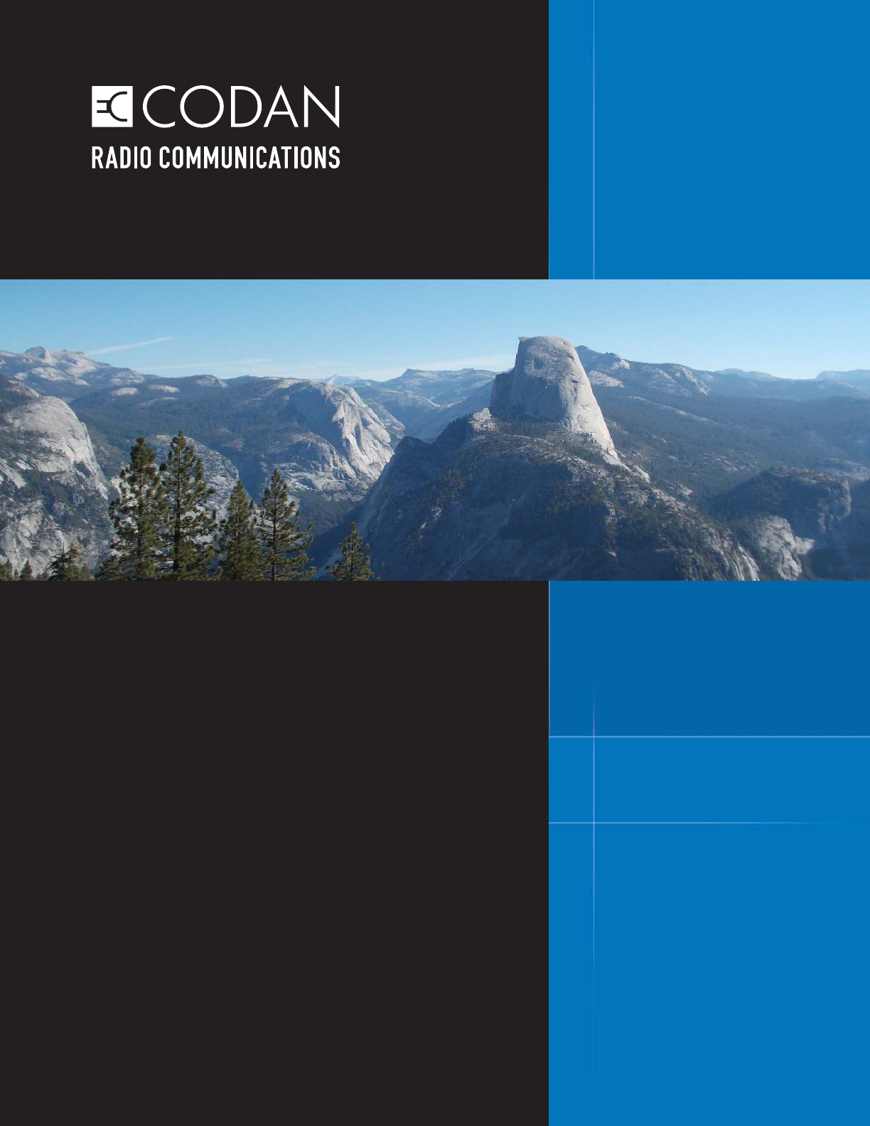
acquire negatively charged particles called electrons.
In the situation when one atom that has acquired an extra electron is in close enough proximity to
another atom that is lacking an electron, the extra electron will “jump” the space between the atoms
(see Figure 1-1). The natural tendency to return to equilibrium and the energy expelled in doing so is
the basis of electricity.
Figure 1-1: Electron Movement
RADIO SYSTEM BASICS & RF FUNDAMENTALS | TRAINING GUIDE
Chapter 1: Introduction Page 3
Now picture this action on a larger scale: in one area there is a material made of a huge number of
atoms in which there is a lack of electrons. In another area there is a material made of a huge number
of atoms in which there is an excess of electrons. In this physically separated state there exists
an amount of electric potential energy, known as potential difference, or voltage, since the excess
electrons naturally want to fi ll the spaces where there is a lack of electrons. Voltage is measured in
the numerical unit Volts (represented by the symbol ‘V’).
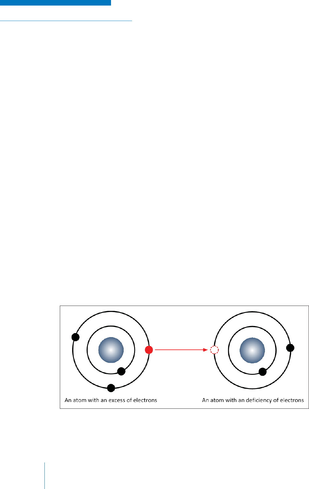
Electrical Circuit
If one were to place a material that allows electrons to move easily (called a conductor) between the
two areas, the potential energy is converted to kinetic energy as the electrons travel from one area to
the other (see Figure 1-2). This fl ow of electrons along the conductor is known as electronic current,
the rate-magnitude of which is measured in Amperes (represented by the symbol ‘A’).
Figure 1-2: Electrical Circuit
The area of excess electrons (known as the negative since it has an excess of negative charges), the
area of lacking electrons (known as the positive, since the lack of negative charges makes it positively
charged) and the conductor make an entirety called a circuit.
One can control the fl ow of electrons through a conductor by adding resistance to the conductor; this
still allows electrons to fl ow, but not as freely as in a simple conductor. As a result, potential energy
is created between the beginning point of the resistance and the end. Resistance is measured in the
numerical units Ohms (represented by the Greek symbol ‘Ω’).
The relationship of resistance, current and voltage is expressed by a mathematical equation known
as Ohm’s Law:
V = I * R
Depending on how the electricity is generated, the current can fl ow steadily in one direction, known as
Direct Current (DC), or it can cyclically change direction at various rates, which is known Alternating
Current (AC).

TRAINING GUIDE | RADIO SYSTEM BASICS & RF FUNDAMENTALS
Chapter 1: IntroductionPage 4
When electricity is applied to an object, it is used to produce work on that object by transferring
electrical energy into another form of energy; for example, when electricity is connected to a lightbulb,
it is used to produce work in the form of light and heat.
The amount of work performed (or more specifi cally the rate at which the work is performed), is
known as the electrical power and is measured in Watts (represented by the symbol ‘W’); power
is therefore often used as a practical measure of how much of something (for example, heat,
light, radiation) is produced by an electric / electronic device. The relationship of power to voltage,
resistance, and current are shown by the mathematical equations below:
P = E * I = I2 * R
Magnetism
Magnetism is a natural force of nature that causes attraction or repulsion of like materials that
produce magnetic fi elds. Magnetism extends from an object in an invisible fi eld that decreases in
strength the further you move away from an object.
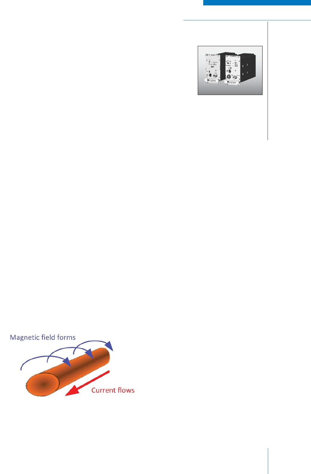
Magnetism and electricity are closely related; when electricity moves through an electrical conductor,
a magnetic fi eld is created around the conductor. Conversely, when a conductive material is moved
through a magnetic fi eld, an electrical current is generated within the conductor.
RADIO SYSTEM BASICS & RF FUNDAMENTALS | TRAINING GUIDE
Chapter 1: Introduction Page 5
Basic Electronic Elements
While this text does not explore radio communication electronics on a circuit level, it is useful to know
the basic electrical elements that comprise electronic circuits:
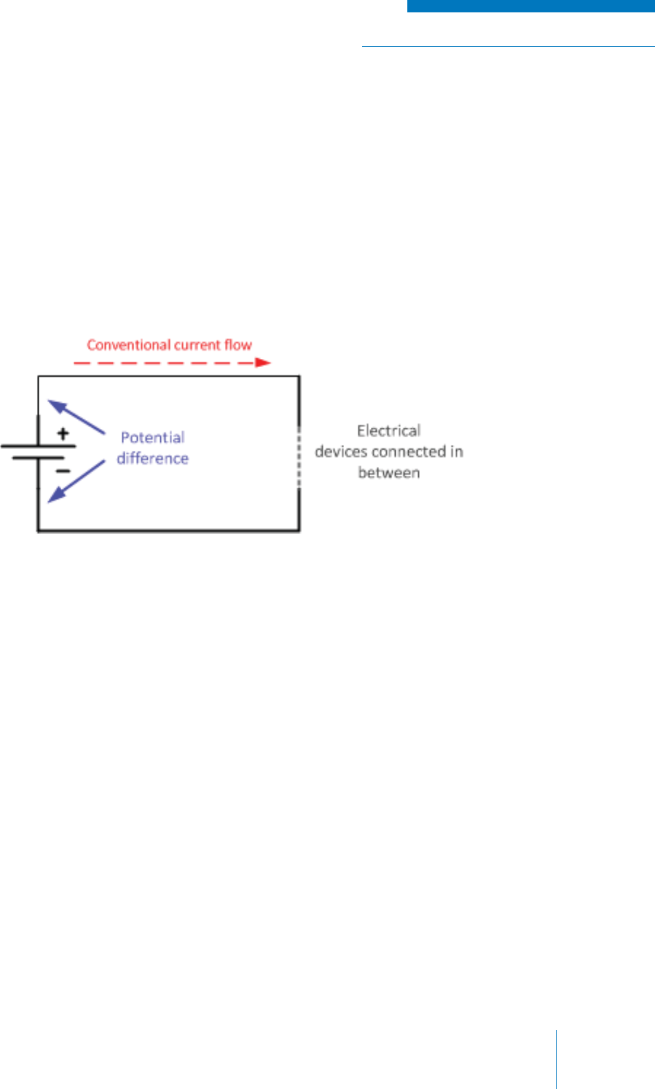
• Resistor: an element made of a material that resists, but does not stop the fl ow of electrons
in an electrical circuit (i.e., adds resistance). A resistor is rated by the unit of resistance;
the ohm (Ω) and retains the same resistance properties in both AC and DC applications.
See Figure 1-3.
Figure 1-3: Resistors
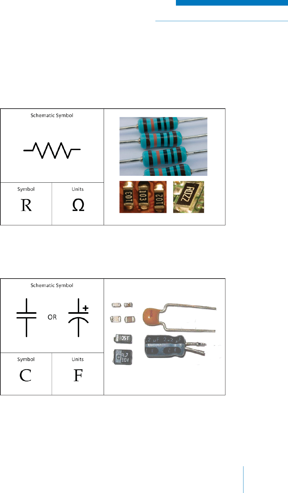
Figure 1-4: Capacitors
• Capacitor: an element made from two conducting plates separated by a non-conducting
material (called a dielectric) that has the ability to store and discharge electric energy. A
capacitor is rated by the unit of capacitance; the Farad (‘F’). See Figure 1-4.
In a DC application, a capacitor has an infi nite resistance, since the two plates of which it
comprises never touch and therefore do not complete a circuit. In an AC application, the
resistive properties decrease as the frequency of the AC voltage increases due to a fi eld of
electric potential being generated between the plates.
TRAINING GUIDE | RADIO SYSTEM BASICS & RF FUNDAMENTALS
Chapter 1: IntroductionPage 6
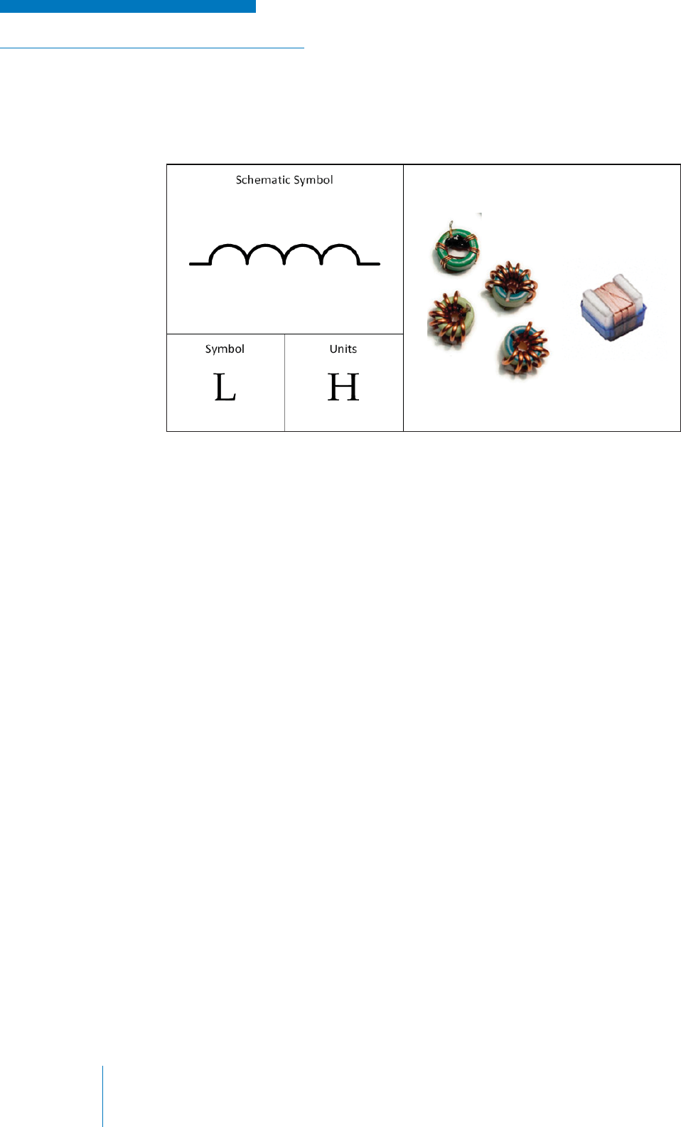
• Inductor: an element made of a conductive wire (typically copper) wound into a coil that
resists changes in current fl ow (not to be mistaken with resistors that resist the current itself).
An inductor is rated by the unit of inductance; the Henry (‘H’). See Figure 1-5.
Figure 1-5: Inductors
In a DC application, an inductor has no resistance, since it is made of a conductive wire. In an
AC application, its resistive properties increase as the frequency of the AC voltage increases
due to the magnetic fi elds generated within the wire.
• Semiconductors: a category of electronic components (rather than a single element
as shown in previous examples), that allows for variable fl ow of current depending on
arrangement and application; for example, a semiconductor device called a diode allows for
current to fl ow in one direction, but not in another. Another example is a transistor, which
allows the current fl owing through it to be varied by external control voltage (or current).
Capacitors and inductors are particularly important in radio communications electronics; their variable
properties when AC electricity is applied are exploited greatly in making radio communications work.
Semiconductors and resistors are ubiquitous throughout all electronics and are also indispensable
when dealing with radio communication technology.
RADIO SYSTEM BASICS & RF FUNDAMENTALS | TRAINING GUIDE
Chapter 1: Introduction Page 7
MATHEMATICAL REPRESENTATIONS
Mathematics is the language that technologists and engineers use to express and understand the
physical and technical phenomenon involved in radio communications. While the mathematics
beyond simple algebraic equations (for example a value x equals a particular number) are all but
omitted from this text, it is unavoidable that some things must be represented using the standard
mathematical representations used in the radio communications industry.
Figure 1-6: Simple Graph Axes
Figure 1-7: Time Graph
Figure 1-8: Frequency Graph
Graphs
A graph (or chart) is a graphical representation
of the mathematical relationship between two
separate types of numerical data.
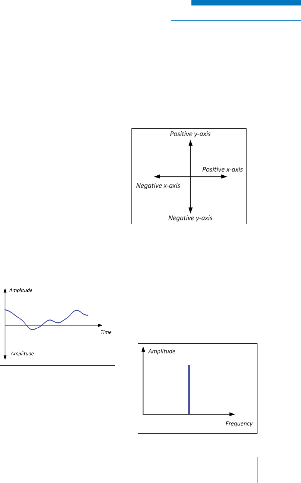
A simple graph consists of two axes: a horizontal
x-axis and a vertical y-axis. Each axis is
assigned a type of numerical data (which may
be positive or negative in value). The body of the
graph is fi lled with individual points, curves or
lines representing the relationship between the
numbers on the x-axis and the numbers on the
y-axis (see Figure 1-6).
The graphs that will be used in this text will
typically have one of the two confi gurations:
1. Amplitude (of Voltage, for example) on
the y-axis versus time on the x-axis,
thus representing how the amplitude
changes over time (see Figure 1-7).
2. Amplitude (of Voltage, for example) on
the y-axis versus frequency on the
x-axis, thus representing what amplitude
is present at a given frequency
(see Figure 1-8).

TRAINING GUIDE | RADIO SYSTEM BASICS & RF FUNDAMENTALS
Chapter 1: IntroductionPage 8
Mathematical Notation
The numbers used to represent values in radio communication can range from the very small to the
very large and are therefore not conveniently expressed using standard numerical terms.
To solve this problem, powers of ten and metric prefi xes are often used.
Powers of Ten
When writing very large or very small numbers, it is most often convenient to not have to write a lot of
zeros or to “round off” digits that are insignifi cant. To do this, one can take advantage of the fact that
multiplying or dividing by 10 moves the decimal point in a number; thus one can express a number as
a small, single digit number multiplied a number of times by ten.
For example:
1,100.0 can be written as 1.1 x 10 x 10 x 10, since this multiplication will result in the original number.
To simplify further, we use powers to avoid writing multiplications of ten, over and over; in the example
we multiply by ten three times, therefore we write 103. Summarizing this example:
1,100.0 = 1.1 x 10 x 10 x 10 = 1.1 x 103 = 1,100.0
Metric Prefi xes
For more commonly used magnitudes of numbers, i.e., those within the range of 10±12, convenient
metric prefi xes are used to ease expression further when stating numbers that have associated units
(i.e., measurements). A metric prefi x is a standard “word” and associated symbol that is attached to
the unit of a measurement, after the number itself, to indicate multiplication by multiples or fractions
(i.e., division) of factors of ten. Adding a metric prefi x allows one to state very large or very small
numbers more easily by moving the decimal point of the number and using the analogous prefi x word
to express its size.
For example, if an element in a circuit has a resistance value of 1100.0 Ω (or “one-thousand, one
hundred ohms”), it is simpler to move the decimal point to the left by three spaces and express the
number as 1.1 kΩ (or “one-point-one kilo-ohms).
The table below (see Table 1) shows the most commonly used metric prefi xes in radio
communications.
Table 1: Common Metric Prefi xes
Metric Prefi x Symbol Multiplier Power of Ten
Tera T 1,000,000,000,000 1012
Giga G 1,000,000,000 109
Mega M 1,000,000 106
kilo k 1,000 103
mili m 0.001 10-3
micro μ* 0.000 001 10-6
nano n 0.000 000 001 10-9
pico p 0.000 000 000 001 10-12
* The Greek letter mu
RADIO SYSTEM BASICS & RF FUNDAMENTALS | TRAINING GUIDE
Chapter 1: Introduction Page 9
Decibels
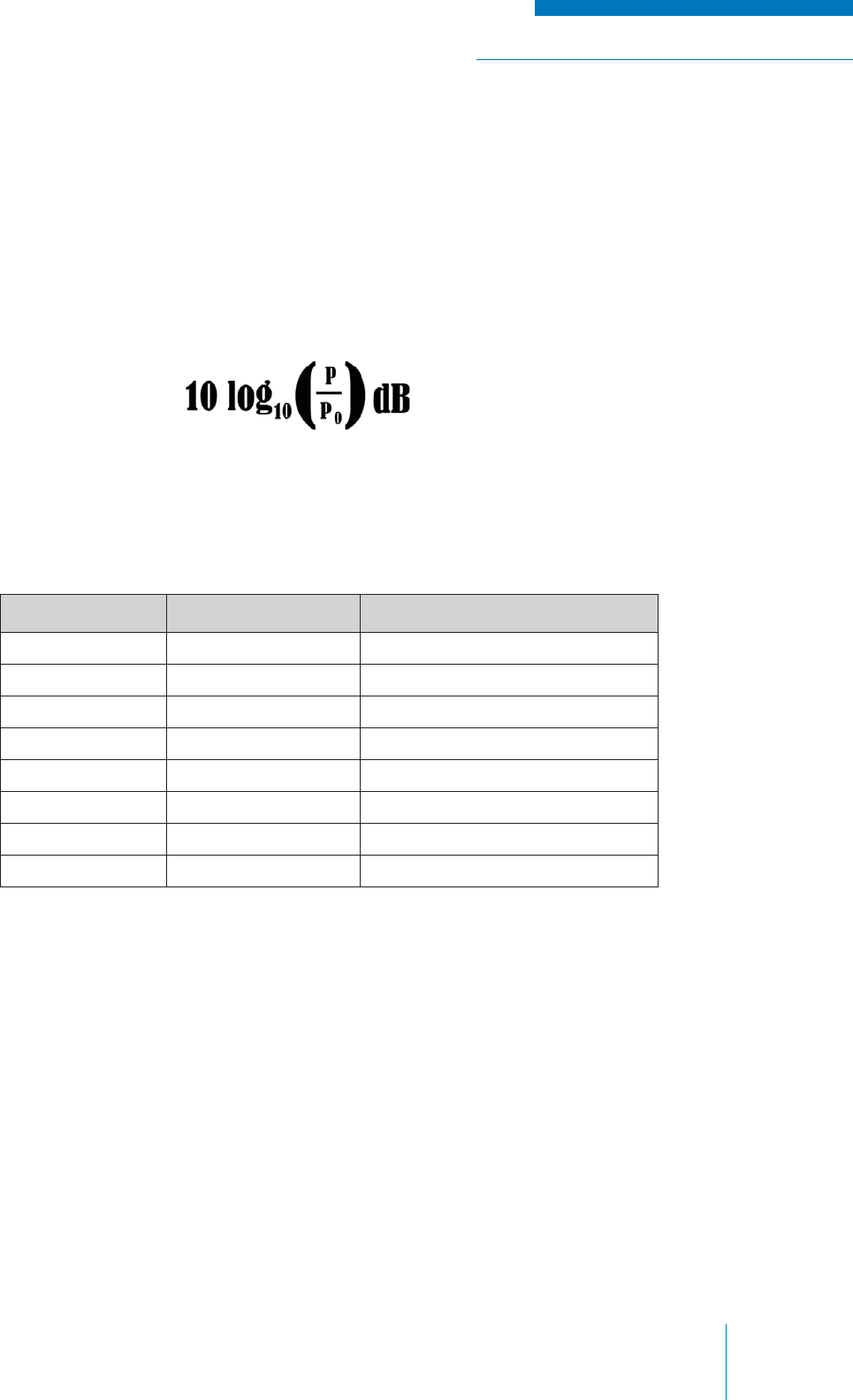
The unit of decibels is a convenient way of expressing the ratio or relative quantity of two numbers.
The symbol for decibels is dB. Decibel expressions are most often used in radio communications to
show a relative increase or decrease in electrical power; typically, the expression is relative to 1W or
1 mW (in which case the symbol is changed to dBm).
The mathematical expression to represent in decibels a given power in watts (P) relative to a
reference power in watts (P0), is shown below:
Using decibels is convenient because it allows large fi gures and fractions to be represented by
smaller whole numbers and because it allows multiple changes in a quantity (like electrical power)
to be more easily calculated using simple addition and subtraction of dB units. The table below (see
Table 2) shows some examples of this expression in practice.
Table 2: Mathematical Expressions for Decibels
Decibels (dB) Power Ratio (P/P0) Notes
20 100 P is 100x greater than P0
10 10 P is 10x greater than P0
3 1.995 (approx. 2) P is approx. 2x greater than P0
0 1 P is the same as P0
-3 0.501 (approx. ½) P is approx. half of P0
-10 0.1 P is 10x smaller than P0
-20 0.01 P is 100x smaller than P0
-60 0.000001 P is one million times smaller than P0

TRAINING GUIDE | RADIO SYSTEM BASICS & RF FUNDAMENTALS
Chapter 1: IntroductionPage 10
A Note About Radio Terminology
The terminology used in electronic communications is often subject to variation due to manufacturer
preference, individual preference and use in other similar technologies and applications.
Readers who have a background in this fi eld or another related fi eld will note that this text may either
call something they are familiar with by a different name, or use a familiar term to describe a different
concept; unfortunately, this often results in confusion.
Listed below are some examples to watch out for in later sections of this guide:
• Manufacturer specifi c terms: The proprietary term ‘PL tone’ is often used instead of the
industry standard term ‘CTCSS tone’.
• Individual preference: To some users, a trunk is an RF link between two sites; to others,
trunking is a form of radio communications using computer control of frequency / channel
selection.
• Variation across similar technologies: The terms ‘Simplex’ and ‘Duplex’ have a different
meaning to IT professionals.
While this guide is written to capture as much of this variation as possible, the fi rst term presented will
always be the industry standard term.
Introduction to Regulatory Bodies
Much of the information presented in this guide is determined by following radio communication
industry standard principles, values and techniques. These are defi ned by a large number of
organizations tasked with licensing, standardizing and providing information to the public. Some of
these organizations are listed below:
• The Federal Communications Commission (FCC) is an independent United States
government agency, charged with regulating interstate and international communications by
radio, television, wire, satellite and cable. The FCC regulates the use of radio spectrum to
fulfi ll the communications needs of businesses, local and state governments, public safety
service providers, aircraft and ship operators, and individuals.
• The National Telecommunications Information Administration (NTIA) is the U.S.
government’s telecommunications policy offi ce. The NTIA assigns and administers
frequencies to federal agencies.
• Industry Canada (IC) is the lead department for radio, spectrum and telecommunications
issues in Canada.
• The International Telecommunication Union (ITU) is a treaty organization affi liated with the
United Nations. Its charter includes the regulation and use of the radio spectrum worldwide.
• The Telecommunications Industry Association (TIA) represents manufacturers of
telecommunications equipment and prepares standards for the telecommunications industry.
TIA represents the communications sector of the Electronic Industries Alliance (EIA).
• The Association of Public-Safety Communications Offi cials International (APCO)
provides leadership; infl uences public safety communications decisions of government
and industry; promotes professional development; and fosters the development and use of
technology for the benefi t of the public.
RADIO SYSTEM BASICS & RF FUNDAMENTALS | TRAINING GUIDE
Chapter 2: Basic Radio Elements Page 11
CHAPTER 2: BASIC RADIO ELEMENTS
THE CONCEPT OF RADIO COMMUNICATIONS
Radio communication is defi ned as the transmission, reception and processing of information over
the air between two locations by using electronic equipment that sends and receives electromagnetic
signals.
The reason that we use radio communications is that, as human beings, our physical senses limit
the distance over which we can receive information from others; we are at the mercy of our eyes and
ears. Radio communications were invented as a means of overcoming these limitations by allowing
people to communicate over vast distances at great speeds by the use of electronic devices.
THE NATURE OF ELECTROMAGNETIC SIGNALS
Electromagnetic Energy
The electronic devices used in radio communication create electromagnetic energy that is “imprinted”
with information that can be perceived and interpreted by humans, such as sound.
Electromagnetic energy is a type of energy that occurs with when particles of matter interact on an
atomic level. It has a component of electric potential and a corresponding magnetic component,
because the movement of electrons (i.e., electricity) creates magnetism. The opposite is also true. If
one moves a magnet around an electrical conductor, an electric current is generated (see Figure 2-1).
Electromagnetic energy is mostly invisible
(the exception being light, which is a form of
electromagnetic energy our eyes are capable of
sensing), travels through the air, and sometimes,
through solid matter. It is all around us at all
times and in varying forms, both naturally and
artifi cially created.
Figure 2-1: Magnetism and Current
TRAINING GUIDE | RADIO SYSTEM BASICS & RF FUNDAMENTALS
Chapter 2: Basic Radio ElementsPage 12
The electromagnetic energy used in radio communications is created by cyclically varying electric
potential (voltage) in a transmission medium, such as a wire or the air (in the case of radio). The
result is a time-varying fi eld of electric potential and magnetic force known as an Electromagnetic
(EM) Field that radiates out from its source in a repeating, wave like manner; hence the often used
term ‘radio waves’.
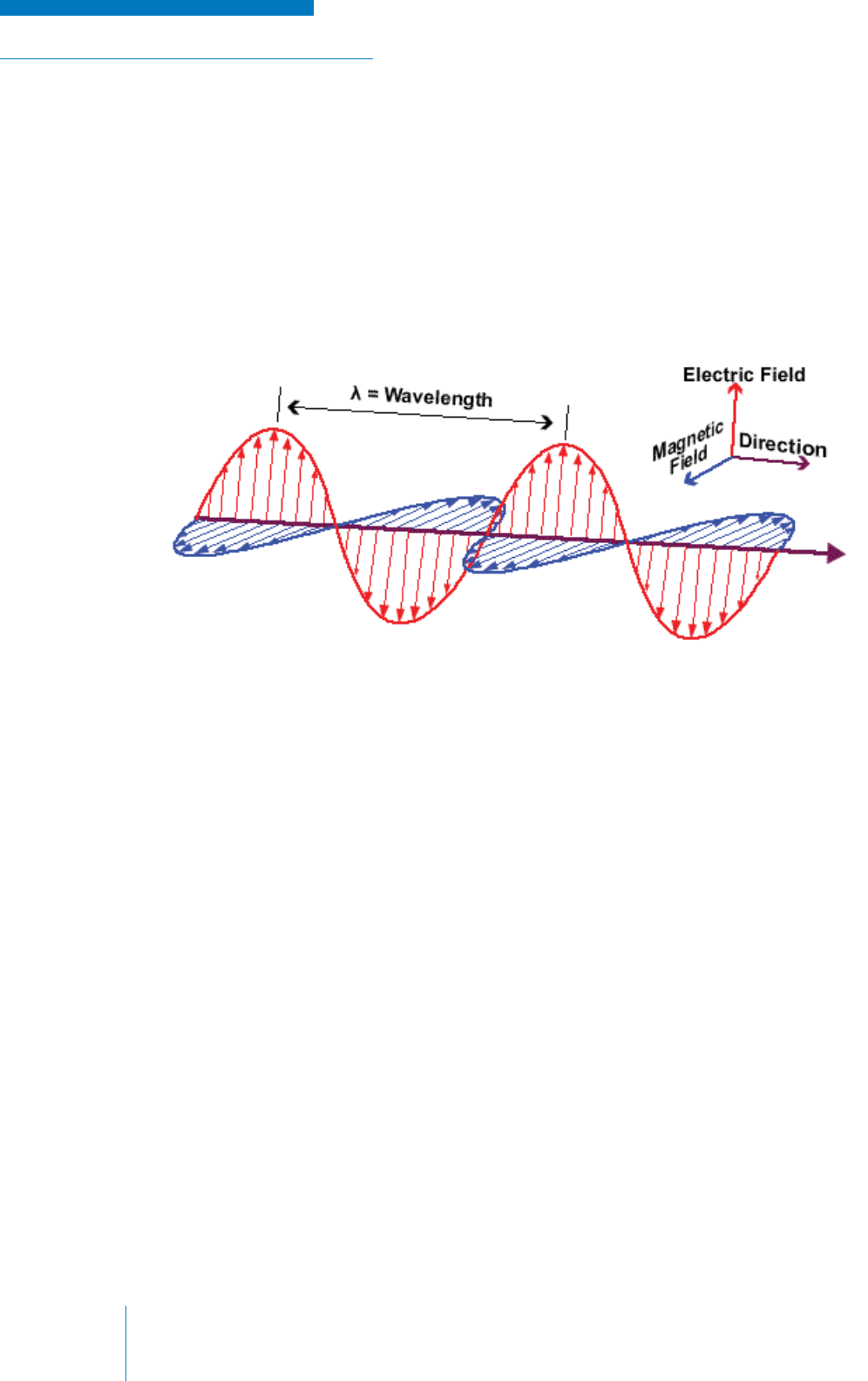
The magnetic and electronic components vary in proportion to each other and both are perpendicular
to each other; the magnitudes of both are perpendicular to the direction in which the wave travels.
This is most easily shown in the diagram below (see Figure 2-2):
Figure 2-2: Illustration of an Electromagnetic Field
Amplitude, Frequency and Power
The wave-like change of electromagnetic energy over time is represented by a sinusoidal (sine)
wave. This has four key attributes that defi ne the nature and behavior of a radio wave:
1. Amplitude
2. Frequency
3. Phase
4. Wavelength
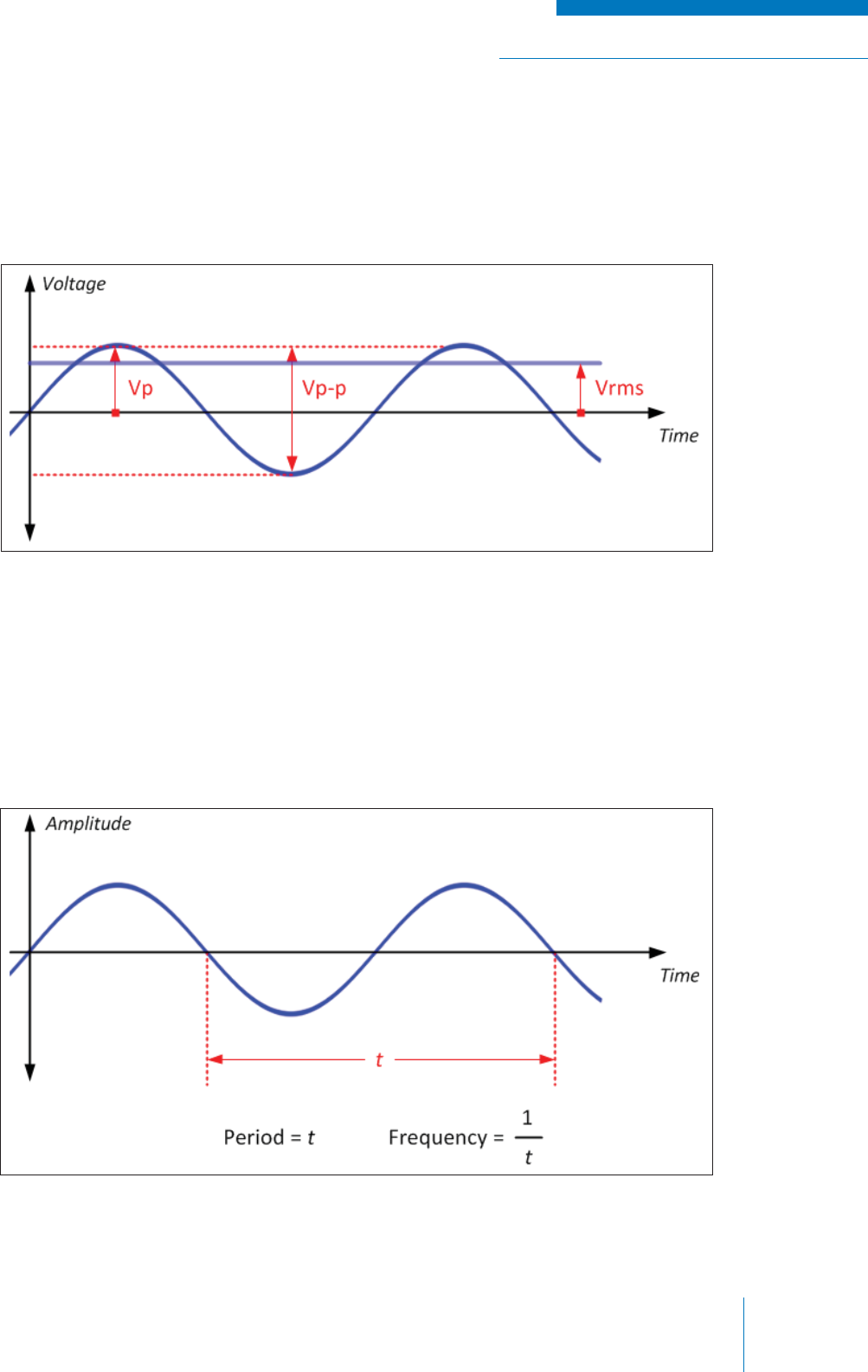
Amplitude (A): The electric potential intensity of the wave (see Figure 2-3). There are several ways
that amplitude can be expressed:
• Instantaneous voltage (v): The voltage value at any given instant of time.
• Peak voltage (Vp): The maximum value that the wave reaches relative to 0V.
• Peak-to-peak voltage (Vp-p): The maximum (most positive) value that the wave reaches
relative to the minimum (most negative) value it reaches.
• Root-mean-square voltage (VRMS): A statistical value representing the average of the
alternating voltage. This essentially represents an AC voltage as a steady, equivalent DC
voltage.
RADIO SYSTEM BASICS & RF FUNDAMENTALS | TRAINING GUIDE
Chapter 2: Basic Radio Elements Page 13
Figure 2-3: Illustration of Amplitude
Figure 2-4: Illustration of Frequency
• Power (P): This expression is common in adio communications, but differs from the other
methods of expressing amplitude because rather than being an expression of voltage, it is an
expression of how voltage, electric current and resistance interact in an electrical element to
produce work. In a typical radio communications example, the electrical element can be an
antenna, and the work produced, measured in Watts (W), is the electromagnetic radiation
produced.
Frequency: The rate at which the electromagnetic wave (or anything cyclical) varies and repeats,
and is measured in a unit called Hertz (Hz), which represents cycles / second. It is calculated by
taking the reciprocal of the interval of time in seconds (called the period) that it took to return to the
same state at which the cyclical event started. One (1) Hz is therefore equal to something repeating
once every second; one thousand cycles is one Kilo Hertz (kHz); one million cycles is one Mega
Hertz (MHz); and one billion cycles is one Giga Hertz (GHz). See Figure 2-4.
TRAINING GUIDE | RADIO SYSTEM BASICS & RF FUNDAMENTALS
Chapter 2: Basic Radio ElementsPage 14
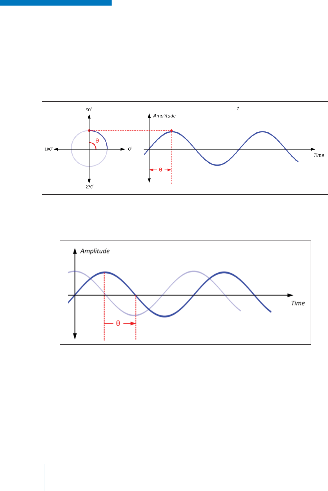
Phase Angle (or simply phase): The trigonometric angle of a sinusoid relative to its origin. It is used
to indicate a point in a sinusoidal wave using degrees (or radians) as the unit of measure. In terms
of a radio wave, it is an indication of the wave’s voltage relative to time. If one relates the sinusoid to
rotation around a circle over time, it is easier to understand this concept.
The diagram below (see Figure 2-5) shows where a phase angle—denoted by the Greek letter
theta (θ)—equal to 90 degrees, can be located on a sinusoid.
Figure 2-5: Illustration of Phase Angle
Figure 2-6: Illustration of Phase Shift
Phase Shift: Occurs when one changes the phase angle at the origin (where t = 0), thereby moving
the sinusoid in time. The diagram below (see Figure 2-6) shows a phase shift of 90 degrees.
Wavelength: The physical distance between the repeating points on a radio wave travelling through
the air. In terms of a radio wave, it is an indication of the wave’s voltage relative to spatial distance.
Wavelength is measured in meters and represented by the greek character λ. Wavelength is inversely
proportional to frequency (as frequency gets bigger, this distance becomes smaller). The term
microwave is often used in communications, referring to frequencies that have a wavelength on the
order of 10-6.
RADIO SYSTEM BASICS & RF FUNDAMENTALS | TRAINING GUIDE
Chapter 2: Basic Radio Elements Page 15
ELECTROMAGNETIC SPECTRUM, CHANNELS AND
BANDWIDTH
The Electromagnetic Spectrum
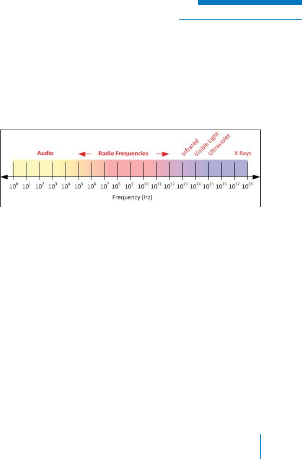
Electromagnetic energy can be arranged on a linear scale according to frequency called a spectrum,
ranging from 0 Hz (does not change at all) to frequencies in the order of 1022 (known as cosmic rays).
This total spectrum is divided into smaller spectrums and useful sections known as bands, which are
defi ned by the type of use or characteristics of the electromagnetic frequencies falling within its range
(see Figure 2-7). These bands are often divided into smaller sub-bands.
The portions of the overall frequency spectrum of particular interest in radio communication are the
Audio Frequency (AF) spectrum and the Radio Frequency (RF) spectrum.
The AF spectrum consists of electromagnetic frequencies that range from approximately from 30 Hz
to 30 kHz. AF signals are equivalent in frequency to the acoustic frequencies that the human ear can
perceive; therefore, if you connect a wire carrying a current varying within this range of frequencies
to a speaker (a device with converts electricity to air vibrations), you will be able to hear these
frequencies. An important distinction to make is that although sound is also referred to in terms of
frequency, it is not itself a form of electromagnetic energy until it is converted with the aid of electronic
equipment.
Figure 2-7: Linear Electromagnetic Spectrum

TRAINING GUIDE | RADIO SYSTEM BASICS & RF FUNDAMENTALS
Chapter 2: Basic Radio ElementsPage 16
The RF spectrum is consists of electromagnetic frequencies suitable for transmitting information
over the air; they are imperceptible to the human senses but can be detected using electronic
equipment. The RF spectrum is divided into the standard operating bands outlined in the table below
(see Table 3).
Table 3: RF Spectrum Operating Bands
Channels
Radio signals can generally exist within the same physical space without interfering with one another
provided that they differ in frequency. Thus, radio systems are allocated very specifi c frequencies
within the operating band of the electromagnetic spectrum by regulatory bodies so they do not
interfere with each other. These subsets of frequency are known as channels.
Designation Frequency Range Wavelength Typical Use
Extremely Low Frequency (ELF) 3 Hz – 300 Hz 10,000 km – 1,000 km Underwater (Submarine)
Ultra Low Frequency (ULF) 300 Hz – 3 kHz 1,000 km – 100 km Ground (Earth-Mode)
Very Low Frequency (VLF) 3 kHz – 30 kHz 100 km – 10 km Radio Navigation, Time Clocks
Low Frequency (LF) 30 kHz – 300 kHz 10 km – 1 km Longwave AM Broadcast, Time, Navigation
Medium Frequency (MF) 300 kHz – 3 MHz 1 km – 100 m Medium-wave AM, Navigation, Ship to Shore
High Frequency (HF) 3 MHz – 30 MHz 100 m – 10 m Long Distance, Ionosphere Skip, Shortwave
Very High Frequency (VHF) 30 MHz – 300 MHz 10 m – 1 m FM Broadcast, LMR, TV Broadcast, Marine
Ultra High Frequency (UHF) 300 MHz – 3 GHz 1 m – 100 mm LMR, TV Broadcast
Super High Frequency (SHF) 3 GHz – 30 GHz 100 mm – 10 mm Radar, Microwave, Cellular, Satellite
Extremely High Frequency (EHF) 30 GHz – 300 GHz 10 mm – 1 mm Radio Astronomy
RADIO SYSTEM BASICS & RF FUNDAMENTALS | TRAINING GUIDE
Chapter 2: Basic Radio Elements Page 17
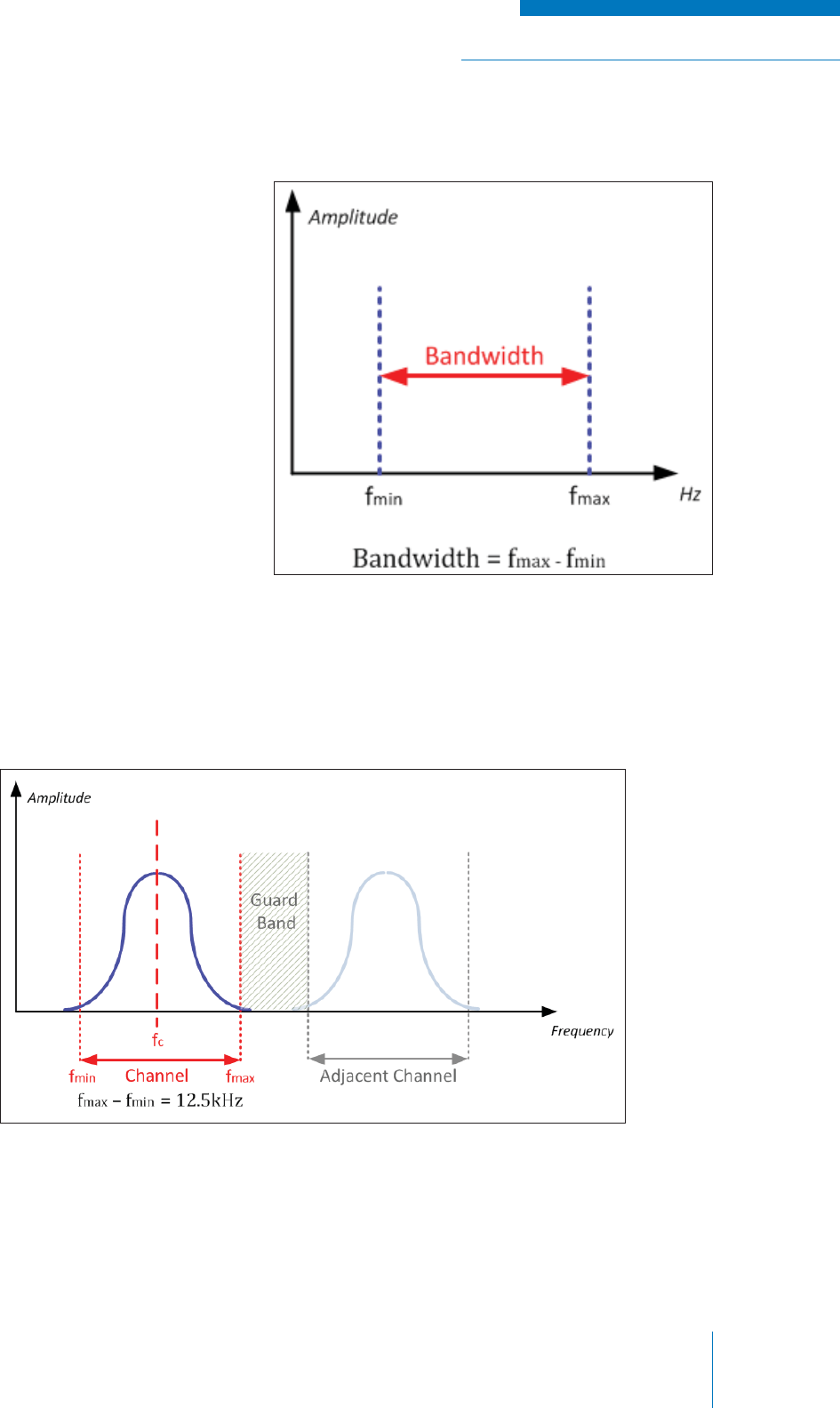
Frequency Bandwidth
The range of frequencies between the
lowest and the highest frequencies that
a channel (or signal within a channel)
occupies is known as the frequency
bandwidth (or most commonly, simply
bandwidth). See Figure 2-8.
Figure 2-8: Illustration of Bandwidth
Figure 2-9: Guard Band Between Channels
In general, the more information that
one wishes to send, the higher the
bandwidth that is required. However, as
the frequencies that regulatory bodies
can allocate become scarcer, various
technologies (some of which are discussed
in a later section of this text) are employed
to make communications more effi cient in
terms of required bandwidth. The process
of converting radio equipment to operate
at higher bandwidth effi ciency is called
narrowbanding.
A channel will typically be of a fi xed bandwidth as defi ned by the regulation of the radio technology
being used. Typical channel sizes in LMR are 6.25 KHz, 12.5 kHz and 25 kHz. A channel will often
have a small amount of frequency band reserved on either side of it to prevent interference from
adjacent channels; this is known as a guard band (see Figure 2-9).
TRAINING GUIDE | RADIO SYSTEM BASICS & RF FUNDAMENTALS
Chapter 2: Basic Radio ElementsPage 18
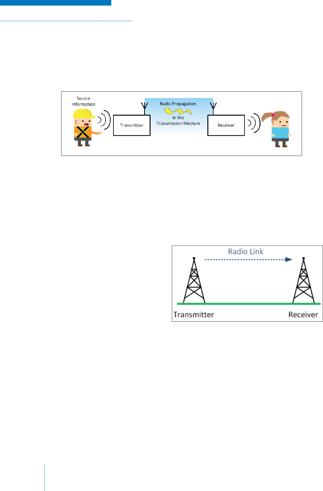
A SIMPLE RADIO COMMUNICATION SYSTEM
The block diagram below (see Figure 2-10) shows the most basic type of radio communications
system in which a single transmitter at one location and a single receiver at another location are
separated by air.
Figure 2-10: Basic Radio System
Figure 2-11: Simple Radio Link
The low frequency source information is input into the transmitter where it is processed and
‘imprinted’ on a radio signal by a process called modulation and then radiated out as a radio signal.
The radio signal travels, or propagates, through the transmission medium (the air) until a receiver
resonates with its frequency—discerning it from all the other RF energy in the air—and ‘extracts’ the
intelligible information via a process called demodulation; after which the radio signal is output for the
‘listener’.
While a single transmitter often reaches
multiple receivers, for the sake of
understanding these concepts it is best to
think of a single transmitter and a single
receiver separated in distance by air. This
simple arrangement is known as a radio
communication link (see Figure 2-11).
These concepts are explored in greater
detail in the next sections.
RADIO SYSTEM BASICS & RF FUNDAMENTALS | TRAINING GUIDE
Chapter 2: Basic Radio Elements Page 19
SOURCE INFORMATION
Source information is the message that we are trying to communicate to our recipient(s). This
information can come in many forms that ultimately fall into two categories: analog and digital.
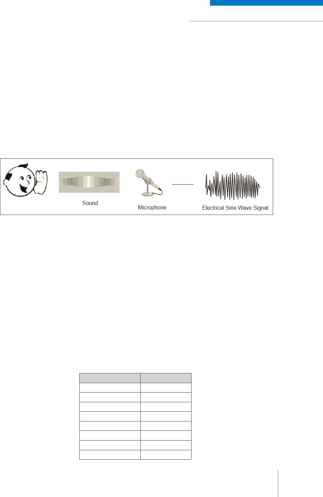
Analog Signals
Information signals vary continuously over time, and when
converted to an electrical signal, produce
an infi nite number of possible voltage values between the two extremes. For example, when a person
speaks into a microphone, there is an element inside the device that converts sound vibrations
into corresponding voltages. The result is an electronic waveform that varies between two limits in
time with the person’s voice (see Figure 2-12). The voltage value of this waveform can take on any
possible value, provided it falls between the set limits of the device.
Figure 2-12: Sound to Wave Signal
Digital Signals
Digital communication is most often associated with new technologies, but the earliest digital format,
Morse Code, was actually the fi rst to be applied to radio communication decades before analog voice
communication appeared.
Unlike analog signals that can have any possible value, these signals can only take on one of a fi nite
number of values at any given time. Most often, digital signals are binary, which means that they
can be one of two possible values: a ‘1’ or a ‘0’. These ones and zeroes are each represented by a
discreet voltage level; typically a ‘1’ is represented by +5V and a ‘0’ is represented by 0V.
Each individual ‘1’ or ‘0’ is called a bit. These bits are grouped together into group of 8 (also known as
a byte), 16, 64 or any other number obtained by making an exponent with a base of two (2n), since
there are two states: ‘0’ and ‘1’. These groups of bits are used to represent larger numbers, letters
or other meaningful information. Below is an example showing how binary numbers are used to
represent the numbers zero through seven.
Table 4: Decimal vs. Binary
Decimal Number Binary Number
0 000
1 001
2 010
3011
4 100
5 101
6110
7 111
TRAINING GUIDE | RADIO SYSTEM BASICS & RF FUNDAMENTALS
Chapter 2: Basic Radio ElementsPage 20
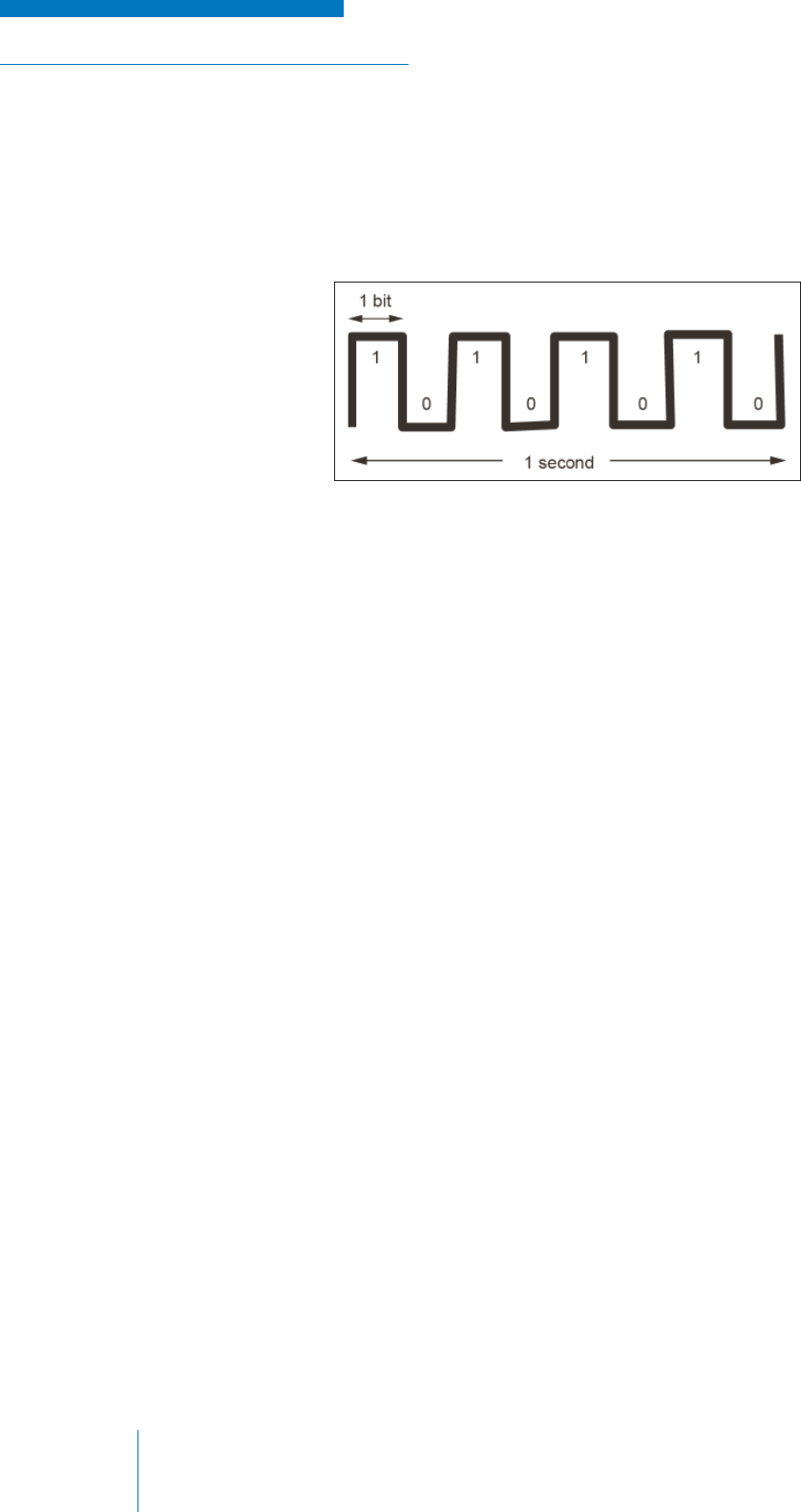
Electronic systems, including communications systems, most often handle these bits one at a time
in what is called a bitstream, making timing an essential part of any digital system. The rate at which
the bitstream is processed is called the bitrate (see Figure 2-13) and is measured in bits-per-second
(bps). Bitrates are usually large in magnitude and use metric prefi xes to simplify notation: kbp
indicates bitrates in the order of a thousand bits-per-second, Mbp in the order of one million bits-per-
second, and so on.
Figure 2-13: Bitrate
An important fundamental concept to understand is that each bit represents information. A single bit
can represent a “Yes” or “No”, an “Off” or “On”, or any other information that can take more states.
The more bits that you combine together, the more complex and detailed the information that can be
represented. With 26 bits, for example, you can represent the English alphabet.
The fl exibility of using bits to represent information, is that it allows one to convey information very
effi ciently. Once again returning to the most basic example of using a single bit to represent “Yes” or
“No”; if one were to speak the word “Yes” into a microphone, it takes about a half second and requires
a full range of voltages to represent the sound. A bit on the other hand can be sent in a tiny fraction of
a second and requires only two voltages to get the message across.
The advantages of digital signals are also not limited to effi ciency. Analog signals are often converted
into digital signals because they are easier to use with computer systems and they are able to resist
the effects of noise. While some information is lost in the conversion—since digital signals cannot
account for every analog level—the result is often indistinguishable, and even better, unwanted parts
of the analog signal can be removed in the process.
Subtones
Not all source information signals are audible or meant for translation for human understanding.
Some information can be added that is meant as instructions for the receiving equipment on how to
operate or which radio signal to listen for. These signals, called subtones, are electrical signals that
are often of a frequency that is too low to be heard by the human ear when applied to a speaker.
The practical application of these signals is described later in this text.
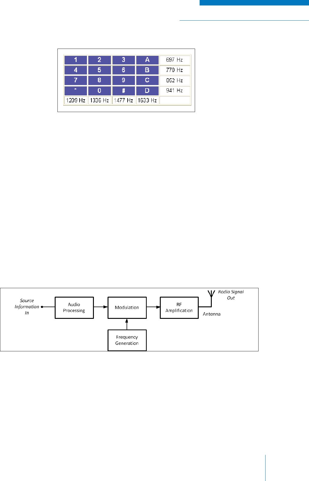
DTMF
DTMF stands for Dual-tone multi-frequency and it is the basis for a telephone system. DTMF is
actually the generic term for Touch-Tone (Touch-Tone is a registered trademark of ATT). When you
press the buttons on the keypad, a connection is made that generates two tones at the same time.
A “Row” tone and a “Column” tone as shown in Figure 2-14. These two tones identify the key you
pressed. When you press the digit 1 on the keypad, you generate the tones 1209 Hz and 697 Hz.
Pressing the digit 2 will generate the tones 1336 Hz and 697 Hz.
RADIO SYSTEM BASICS & RF FUNDAMENTALS | TRAINING GUIDE
Chapter 2: Basic Radio Elements Page 21
TRANSMISSION
The function of the transmitter is to interpret the source information, which is in the form of a low-
frequency electronic signal, and ‘imprint’ it on a high frequency carrier signal that can travel long
distances over the transmission medium to the receiver.
Although transmitters are often complex electronic devices, their operation can be summarized by the
following functional stages (see Figure 2-15):
1. Audio Processing
2. Frequency Generation
3. Modulation
4. RF Amplifi cation
5. Antenna
Figure 2-14: DTMF Tone Chart
Audio Processing
The fi rst function of the transmitter is to take an external form of source information and convert it to
electrical signals that can be used within the transmitter.
Audio Conversion and Analog Signal Processing
Analog information is most often created when sound pressure waves (for example, person’s voice)
are applied to a microphone; an element within the microphone vibrates in step with the sound; and
the sound is converted into an analog audio electrical signal.
DTMF signals can be easily transmitted over a radio system, as all of the tones are in the standard
audio frequency range (300 – 3000 Hz). A DTMF code (sequence of numbers) can be sent over the
radio system and a corresponding DTMF decoder can detect the appropriate code and then be used
to turn devices on or off, to allow for remote signaling, operating lights, relays or alarms.
Figure 2-15: Transmitter Block Diagram
TRAINING GUIDE | RADIO SYSTEM BASICS & RF FUNDAMENTALS
Chapter 2: Basic Radio ElementsPage 22
In converting sound into an electrical signal, there are some parts that are unwanted as they do not
convey intelligible information. Also, since the human voice (or other sounds) can vary to an almost
infi nite degree in magnitude and frequency, some compensation must be made in order to work within
the limitations of the electronic transmitting equipment.
Therefore, the audio signal is processed after it is introduced into the transmitter to eliminate or
enhance frequency and amplitude characteristics and make the signal ready for transmission.
In a process called companding, the audio signal can be amplifi ed (made stronger) or attenuated
(made softer) depending on the volume of the speaker’s voice. This process ensures that quiet
(small) signals get included in the transmission and that loud (large) signals do not get distorted by
the electrical equipment.
Audio fi lters are used to eliminate the extreme high and low audio frequencies that fall outside of the
typical range of human hearing, as well as other unwanted frequencies that can be considered as
noise in an audio signal.
Shaping circuits make the higher audio frequencies greater in amplitude to improve the modulation
process that follows. This process is called pre-emphasis since it emphasizes the higher frequency
audio signals.
The addition of subtones and other control signals also occurs in the signal processing stage.
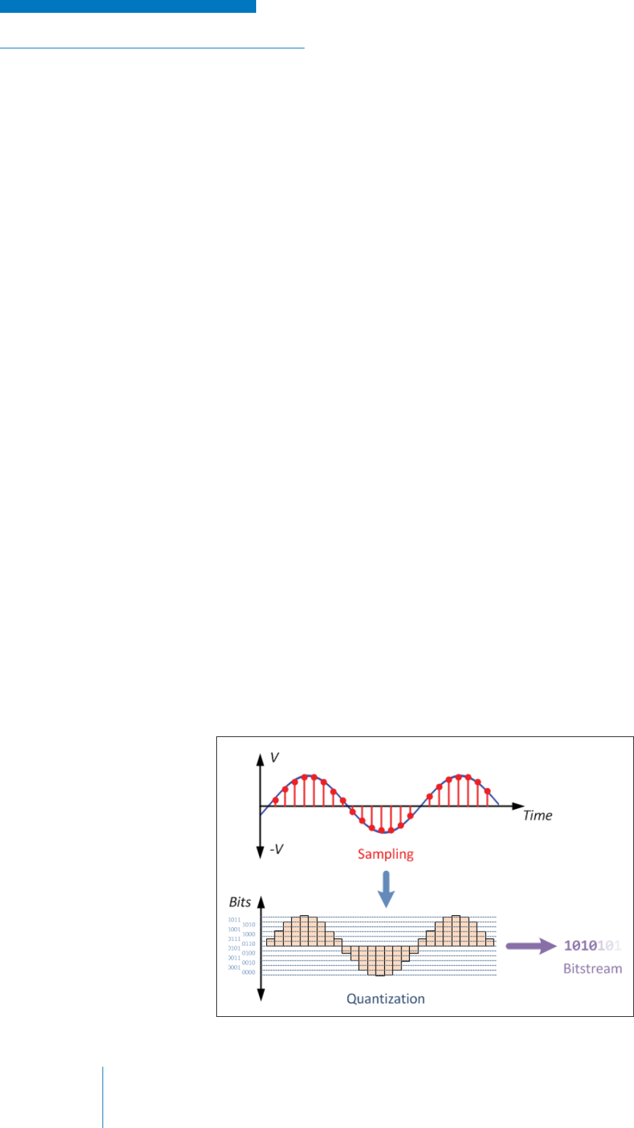
Analog-to-Digital Conversion and Digital Signal Processing
Quite often, analog signals will be converted into digital information within the transmitter before being
sent, and converted back to analog audio upon being received by the receiver. This process, known
as Analog-to-Digital Conversion (ADC), is advantageous because the process eliminates noise
inherent in the analog signal and allows for error detection and correction capability.
The conversion process involves fi rst sampling the analog signal (i.e., determining the instantaneous
voltage level value at regular discreet intervals), then quantizing the samples by assigning a weighted
binary value to voltages depending on where they fall within pre-determined voltage ranges (this
process is called quantization). The result is a stream of binary bits representing the original analog
waveform. See Figure 2-16.
Figure 2-16: Analog-to-Digital Conversion Process
RADIO SYSTEM BASICS & RF FUNDAMENTALS | TRAINING GUIDE
Chapter 2: Basic Radio Elements Page 23
Figure 2-17: Oscillators
Once the signal is converted from analog to digital (or a digital signal is input directly into the
transmitter), a Digital Signal Processor (DSP) can perform functions that are equivalent to the
companding, fi ltering and shaping functions in analog processing. The DSP can also introduce
additional error detection and correction information into the signal that tells the receiver that the
signal it has received is free of error.
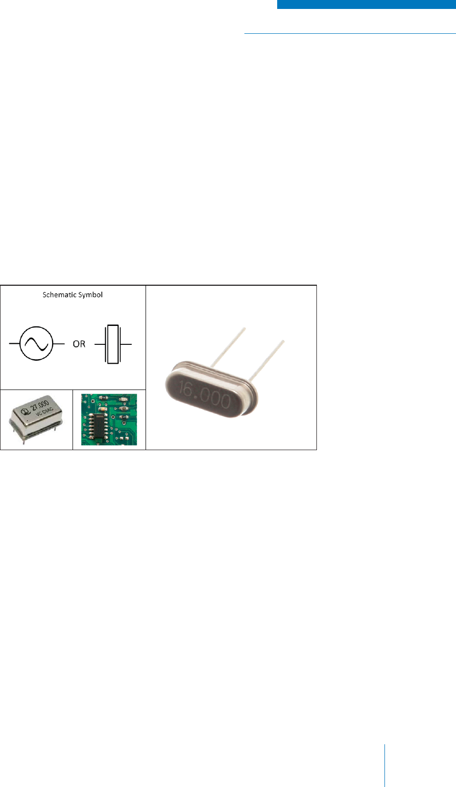
Frequency Generation
While the AF signal is generated by the user’s voice and the audio processing circuitry, a device
called an oscillator generates the high-frequency RF signal. When this device is internal to a piece of
equipment like a transmitter (or receiver), it is often referred to as the Local Oscillator (LO).
Oscillators
The oscillator device is used to produce a high frequency electrical sinusoidal waveform
(see Figure 2-17).
The key performance metric in an oscillator is frequency stability, which is the ability of the oscillator
to produce and sustain a signal of precise frequency. Often the frequency produced by the oscillator
can be externally varied by applying an external control such as voltage (this is useful for devices that
operate on multiple frequencies).
There are various types of oscillators employing different technologies depending on application and
constraints (such as cost). The two most commonly used in basic radio applications are:
1. Voltage Controlled Oscillators (VCO): a device made of various electronic elements that
produces a signal whose frequency can be controlled / varied by applying an external DC
bias voltage.
2. Crystal Oscillators: a device that uses a special type of crystal that generates a very precise
electrical signal when mechanical pressure is applied. This is known as the piezoelectric
effect. Crystal oscillators are susceptible to reduced frequency stability with changes in
temperatures, so they are often compensated using electrical circuits. These devices are
known as Temperature Compensated Crystal Oscillators (TCXO).
TRAINING GUIDE | RADIO SYSTEM BASICS & RF FUNDAMENTALS
Chapter 2: Basic Radio ElementsPage 24
Carrier Signal
The basic RF signal produced by the oscillator in a transmitter is known as the carrier signal. The
carrier signal is simply a sinusoidal (time-varying) electrical signal that has a frequency in the RF
range. The frequency of the carrier is the frequency that the device is set to operate at (i.e., if you
have a transmitter operating at 450 MHz, the carrier signal is oscillating at 450 MHz).
The carrier is the signal that the receiving equipment is designed to “listen” for, but in itself it does
not contain any information; the information must be added to the carrier by a processed called
modulation.
Modulation
Modulation is the process of ‘imprinting’ the low-frequency source information signal on the carrier
signal by changing its properties.
As with any sinusoidal signal, the carrier signal has three properties that can be varied:
1. Amplitude: the voltage magnitude of the carrier signal.
2. Frequency: the rate at which the signal varies with time.
3. Phase (or angle): the relative trigonometric phase angle of the signal.
The type of modulation is defi ned by which of these attributes of the carrier signal are modifi ed by the
application of the source information. The type of modulation used is the key defi ning characteristic of
the transmitter and by extension the radio system.
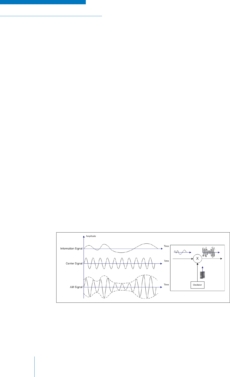
Amplitude Modulation
In a transmitter employing amplitude modulation (AM), the amplitude of the carrier signal is varied in
time with the amplitude of the source information. This process in the time domain is shown below
(see Figure 2-18).
Figure 2-18: Amplitude Modulation Process
NOTE: Image is courtesy of Wikimedia Commons
RADIO SYSTEM BASICS & RF FUNDAMENTALS | TRAINING GUIDE
Chapter 2: Basic Radio Elements Page 25
Note that the amplitude of the carrier signal takes on the shape of the source signal, but the
frequency of the carrier signal remains constant. The shape of the source signal is also mirrored
on the negative portions of the carrier wave. The overall positive and negative shape that limits the
amplitude the carrier signal is called the envelope.
The process by which the source signal is applied to the carrier signal is called frequency mixing,
and in it the two signals are essentially multiplied together using non-linear electronic devices.
This process has a by-product in the form of additional, less powerful signals above and below the
carrier frequency. While these frequencies, known as sidebands (SB) are generally unwanted as
they occupy more bandwidth, there are some radio applications in which they are used to convey
information as well.
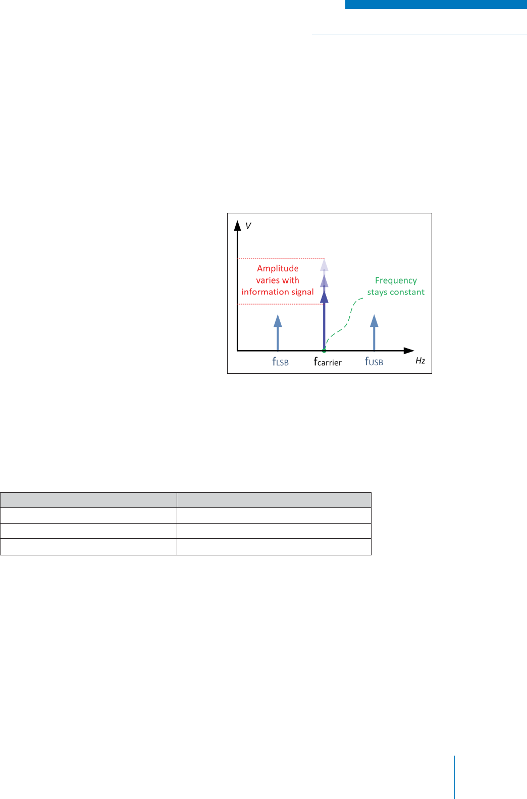
Figure 2-19: AM Signal in Frequency Spectrum
When viewed in the frequency spectrum, an AM
signal appears as shown (see Figure 2-19).
Although AM radio systems are increasingly more rare due to the spread of frequency modulation
technology, there are still many applications that use AM radio, such as commercial broadcast radio,
marine and aircraft communications. The table below (see Table 5) summarizes the advantages and
disadvantages of AM radio.
Table 5: AM Radio Comparisons
Advantages Disadvantages
Inexpensive equipment Poor sound quality
Is able to travel far with less power Susceptible to noise and interference
Requires little bandwidth
TRAINING GUIDE | RADIO SYSTEM BASICS & RF FUNDAMENTALS
Chapter 2: Basic Radio ElementsPage 26
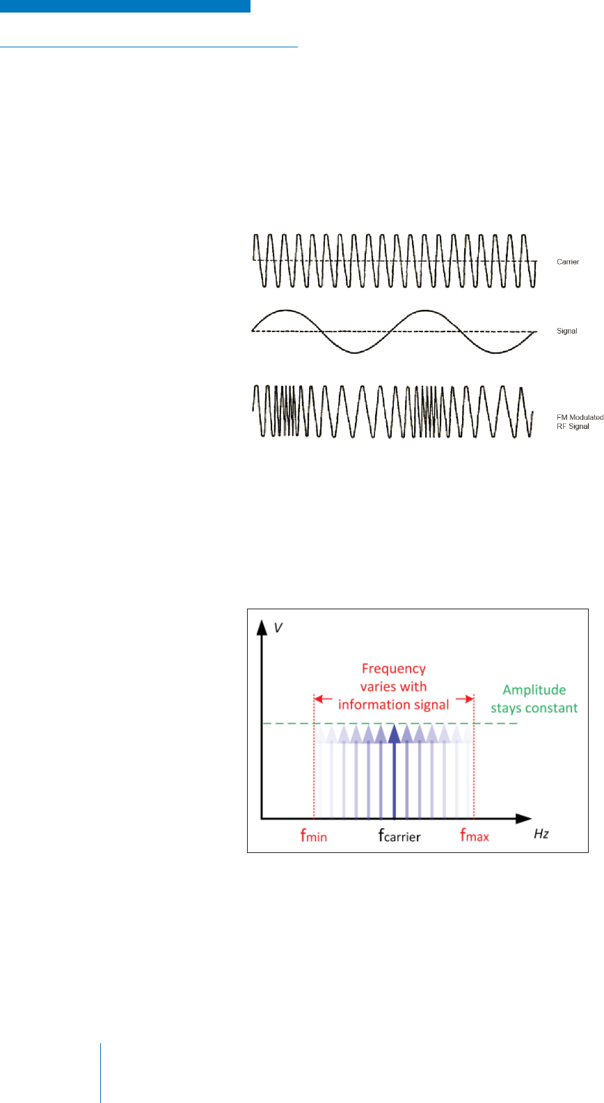
Frequency Modulation
In a transmitter employing frequency modulation (FM), the frequency of the carrier signal is varied in
time with the amplitude of the source information.
Note that the frequency of the carrier signal increases and decreases, but the amplitude of the carrier
signal remains constant (see Figure 2-20).
Figure 2-20: Frequency Modulation Signal
Figure 2-21: Carrier Frequency Graph
When viewed in the frequency domain, an FM signal appears as shown below (see Figure 2-21).
The center line is the carrier frequency and the occupied areas to either side of it represent the
possible frequencies that can occur as the carrier is varied with the source information. This is why
FM requires more bandwidth; the more the signal varies, the more possible frequencies need to be
made available, thus the required channel size grows.

RADIO SYSTEM BASICS & RF FUNDAMENTALS | TRAINING GUIDE
Chapter 2: Basic Radio Elements Page 27
The variation of the signal from the carrier frequency is known as the frequency deviation of the
signal. This is limited within a transmitter to ensure that the transmitted frequency does not go outside
of its designated channel.
FM is currently the pre-dominant choice of technology in radio communications and, with the
reduction of price in FM electronics, this trend is likely to continue. The table below summarizes the
advantages and disadvantages of FM Radio over AM radio (see Table 6).
Table 6: FM Over AM Comparison
Advantages Disadvantages
Less prone to interference Requires a high bandwidth
Better sound quality upon reception Lower range and requires more power
Equipment is more expensive
FM is typically implemented by using the modulating signal as a control voltage for the VCO.
Phase Modulation
Phase modulated (PM) signals are extremely similar to FM signals because the phase and frequency
of a signal are mathematically related to one another. That is, when the frequency is varied in an
FM signal, the phase of that signal is indirectly varied and vice versa. Therefore, the only difference
between the two is which aspect you are varying directly and which you are varying indirectly.
When viewed in the time-domain, the signals are identical except for how they relate to the source
information in time. In the frequency domain, since frequency is changed with phase, the signal looks
exactly the same as an FM signal.
The variation of the carrier frequency phase in time with the source information is known as the
phase deviation of the signal.
TRAINING GUIDE | RADIO SYSTEM BASICS & RF FUNDAMENTALS
Chapter 2: Basic Radio ElementsPage 28
Digital Forms of Modulation
The descriptions of modulation schemes given above all used analog source information. For digital
source information, the carrier signal is also varied in amplitude, frequency or phase, but the variation
is rapid rather than gradual with a bit being mapped to a particular amplitude, frequency or phase.
The most simple, low performance form of digital modulation is called keying, in which a single bit of
the information signal is represented by a quick change in characteristic in the carrier signal.
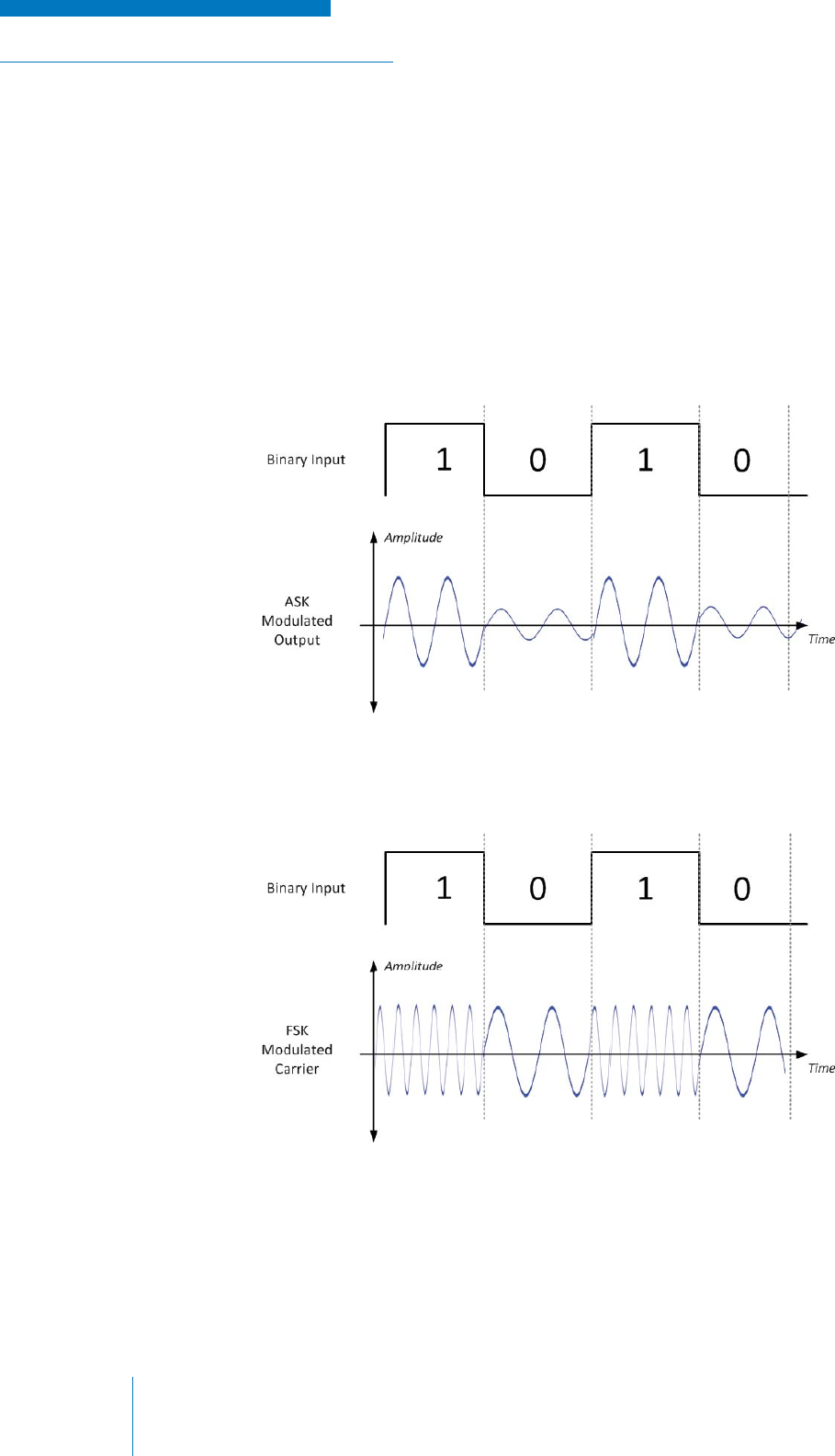
• Amplitude Shift Keying (ASK): The amplitude of the carrier is higher for a “1” bit and lower
for a “0” bit. The most extreme form of this is called On-Off Keying (OOK), in which the carrier
is turned off (reduced to 0V) to represent a binary “0”. See Figure 2-22.
Figure 2-23: FSK Modulation Diagram
Figure 2-22: ASK Modulation Diagram
• Frequency Shift Keying (FSK): The frequency of the carrier is deviated to its maximum for a
“1” bit and deviated to its minimum for a “0” bit. See Figure 2-23.
RADIO SYSTEM BASICS & RF FUNDAMENTALS | TRAINING GUIDE
Chapter 2: Basic Radio Elements Page 29
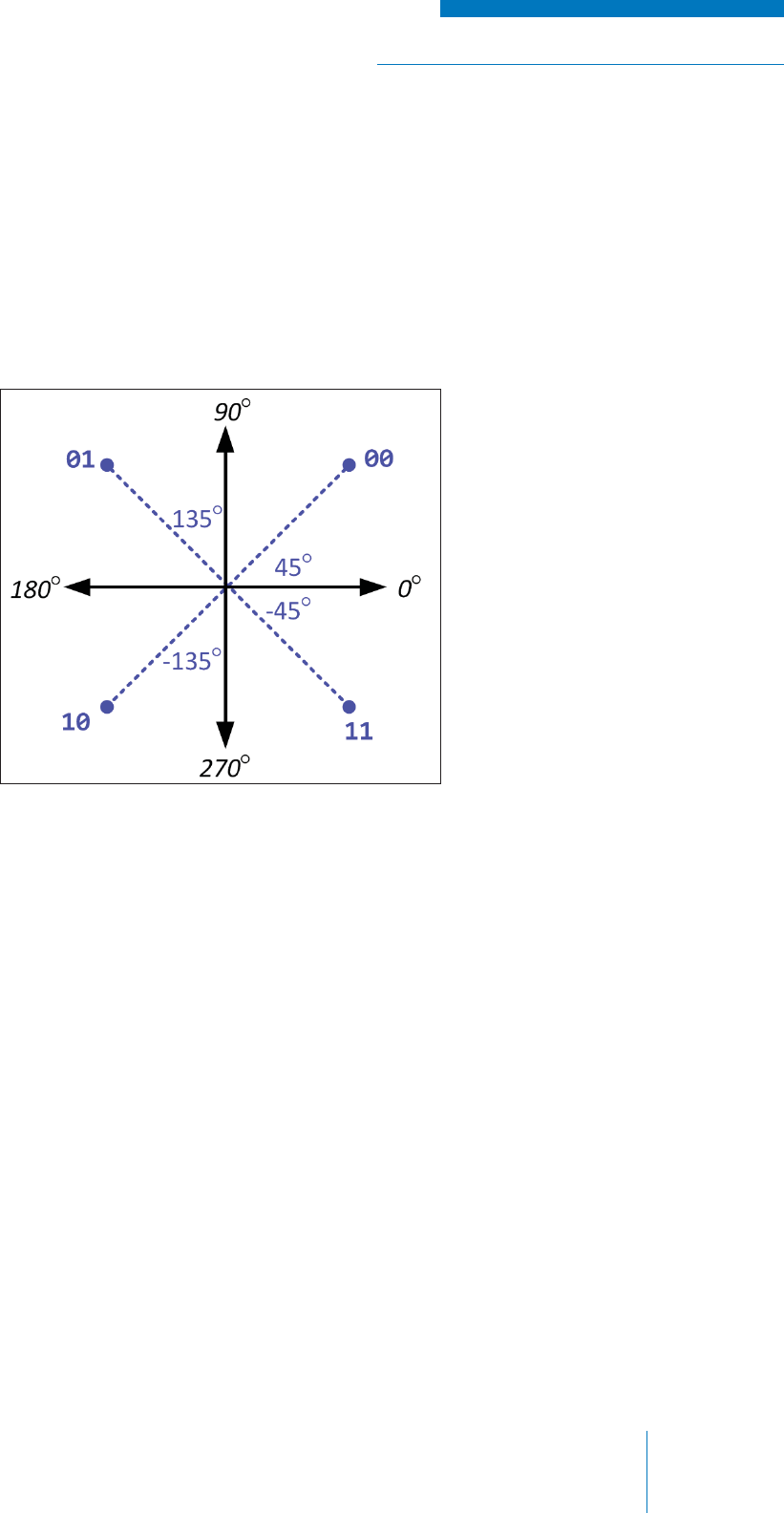
More advanced forms of PSK combine groups of bits together and assign them a corresponding
phase. In doing this, the transmission of data becomes faster because a single change in phase
can represent a larger number of bits and by extension information. For example, Quaternary Phase
Shift Keying (QPSK) uses four different phases (45°, -45°, 135°, -135°) to represent four different
combinations of bits (00, 01, 10, 11); 8-PSK uses eight different phases to represent eight different
combinations of bits, and so on. See Figure 2-24.
Figure 2-24: QPSK Phases
• Phase Shift Keying (PSK) or Binary Phase Shift Keying (BPSK): The phase of the carrier
is shifted by 180° for a “1” bit and remains at 0° for a “0” bit.
Even more advanced forms of digital modulation schemes, called Quadrature Amplitude
Modulation (QAM), combine both phase and amplitude modulation to represent combinations of bits,
making the transmission of information even more effi cient. For example, 8-QAM uses four different
phases in combination with four different voltages to represent eight different combinations of bits.
TRAINING GUIDE | RADIO SYSTEM BASICS & RF FUNDAMENTALS
Chapter 2: Basic Radio ElementsPage 30
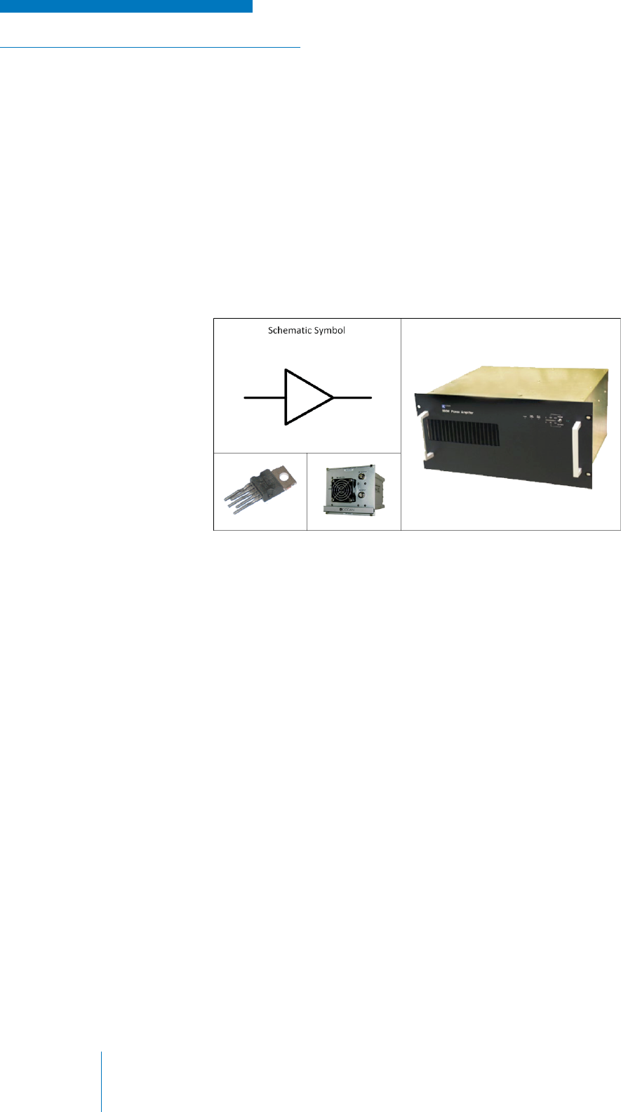
Figure 2-25: Amplifi ers
RF Amplifi cation
The signals within a transmitter are relatively weak (low in voltage / power) since smaller signals are
easier to work with in the initial stages of conversion and modulation; however, in order to have the
modulated RF carrier signal travel long distances, one must make them stronger in power through a
process called amplifi cation.
Amplifi ers
Electronic devices and/or equipment called amplifi ers perform the process of signal amplifi cation by
re-creating the shape of a small voltage time-varying input signal with a larger voltage power supply
(see Figure 2-25).
The operation of an amplifi er is characterized by a number metrics, the most important of which are:
• Gain: the amount a signal increases in power or voltage between the input of the amplifi er
and the output. Gain is the key defi ning characteristic of an amplifi er. It is in essence a
unitless number representing the ratio between the input and output voltage, current or
power; so one can simply take the voltage at the input, for example, and multiply it by the
gain to determine what the voltage at the output would be.
However, in practice it is most often represented in decibels (dB or dBm) relative to input.
This is done so that gain can be more conveniently calculated in the situation where there are
multiple amplifi ers (or other elements that have gain) arranged one after another.
• (Frequency) Bandwidth: the range of frequencies that the input signal can have for the
amplifi er to work correctly and not be damaged. Amplifi ers are devices that are sensitive to
frequency. If a frequency is input that falls outside of the amplifi er’s operating bandwidth, it
may either not be amplifi ed to the level that is expected, or in extreme cases, may cause the
amplifi er to become unstable and oscillate, thus creating a large unwanted output that can
damage the amplifi er and other equipment connected to it.
• Noise: how much noise is added to the output signal during the amplifi cation process.
Since the amplifi er is taking a small signal and “converting” it to a larger signal, it may also
take some unwanted voltages in the circuit and make them larger as well. These unwanted
voltages, caused by random electronic effects or external signals leaking into the circuit, are
normally too small to be noticed, but when amplifi ed can be problematic and can damage the
overall quality if the intended signal.

RADIO SYSTEM BASICS & RF FUNDAMENTALS | TRAINING GUIDE
Chapter 2: Basic Radio Elements Page 31
• Effi ciency: how effi ciently the input signal is amplifi ed to the output signal and how much
power is lost in the process in the form of heat or other factors
• Linearity: how proportional the output signal is to the input signal. Ideally, the output signal
would be completely proportional to the input signal; that is, the shape of the output signal
would be exactly the same as the input signal, only larger in magnitude. In practice, the
electronic devices used in the amplifi cation process are overall non-linear and only have a
range of voltages in which the input and output behave proportionally.
• (Input/Output) Dynamic Range: the smallest and largest signals that can be input / output
by the amplifi er. The input dynamic range defi nes what signal is too small for the amplifi er
to discern and make larger, and how large an input signal can be before the amplifi er can
no longer make it larger without distorting the signal. The output dynamic range defi nes the
smallest and largest signals produced at the output by the amplifi er. In essence, this is the
voltage equivalent to the frequency bandwidth.
• Time Response: since the amplifi cation process is not instantaneous, there are a number of
time factors that need to be considered, such as how quickly the output signal changes with
respect to the input signal, or how quickly the input signal can change before the amplifi er
can no longer keep up with changing the output signal (known as the Slew Rate)
Amplifi ers can take many forms, from tiny integrated circuits within a transmitter (or other electronic
equipment) to a very large, standalone pieces of equipment, depending on their use and the amount
of power they are expected to output.
It can be generally assumed that a transmitter will have some form of amplifi er built-in, as it is an
essential part of transmitter operation. Additional amplifi ers are often connected to the output of the
transmitter to further boost the power of the transmitted signal. The addition of one or more amplifi er
to an output of a preceding amplifi er is called cascading and each individual amplifi er within such a
system is called a stage. While cascading amplifi ers increases the overall output power, care must
be taken that the input and output signals of each stage do not exceed regulatory limitations and the
capabilities of the other equipment in the system.
Antenna Interface and Transmission
The fi nal stage in the transmission process is to transfer the modulated and amplifi ed RF carrier
signal from the transmitting device to the air via a metallic electrical conductor system called an
antenna. To understand this process, we must fi rst address the important topic of impedance and how
it affects the transfer of electrical power from one place to another.
Impedance Matching, VSWR and Refl ected Power
Impedance is the apparent electrical resistance of elemental electronic components (i.e., resistors,
capacitors and inductors) when high-frequency signals are applied. The elements within a high-
frequency electronics device, such as a receiver or transmitter, have to be impedance matched to
ensure that the high-frequency electrical signal gets transferred from one element or circuit to another
as effi ciently as possible.
TRAINING GUIDE | RADIO SYSTEM BASICS & RF FUNDAMENTALS
Chapter 2: Basic Radio ElementsPage 32
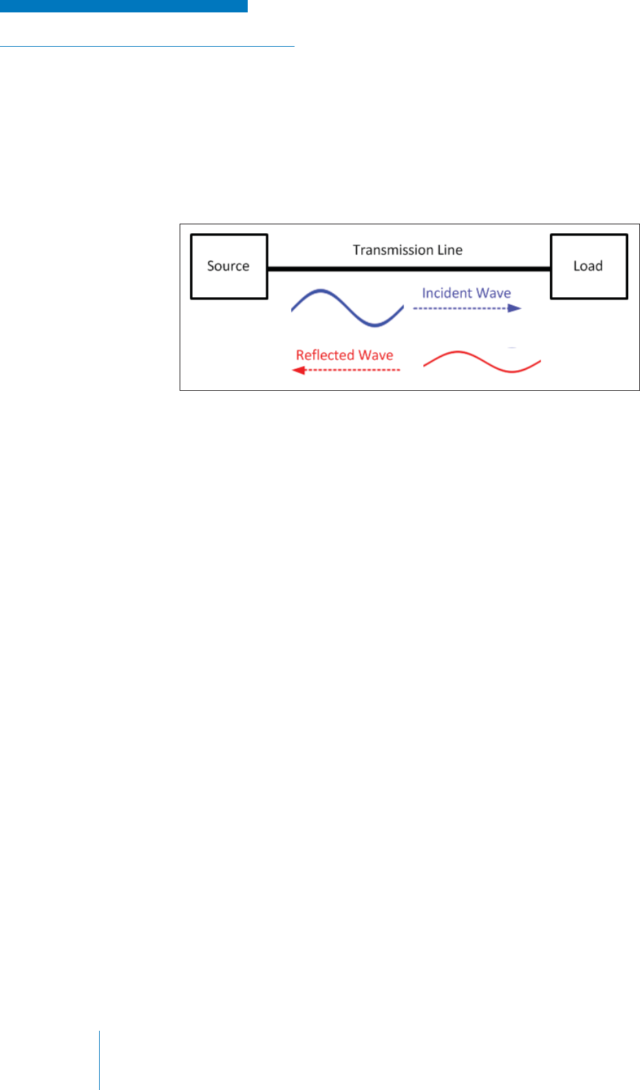
Figure 2-26: Coupled Energy
In a properly impedance matched circuit all of the power in the electrical signal is transferred from
the output element (commonly referred to as the source) to the input element (commonly referred
to as the load) without loss. The time varying electrical signal that gets transferred is called the
incident wave. When the impedance of the source does not match the impedance of the load, some
of the power of the incident wave is refl ected at the junction of the two elements back into the output
element, producing a refl ected wave. The energy that is transferred from the incident wave is called
the coupled energy. See Figure 2-26.
The ratio between refl ected power and incident power is the Voltage Standing Wave Ratio (VSWR).
The ideal condition is when VSWR = 1, which means that the all incident energy is transferred and
nothing is refl ected. One will often fi nd a VSWR rating on radio communication, which should be as
close as possible to 1, keeping in mind that a perfect VSWR is hard to achieve in practice.
The pertinent example of this is the attachment of an antenna (the electrical load) to the transmitter
amplifi er (output source). If both the output of the amplifi er and the antenna are functioning properly
and have the same rated impedance (typically 50Ω), the VSWR at the junction between the two will
be approximately equal to 1, and the full power of the transmitter will be transferred to the antenna
and transmitted.
If the antenna is faulty and does not have an input impedance of 50Ω, the VSWR will be greater
than 1 and some of that power will be refl ected back into the amplifi er instead of being transmitted;
this will not only limit the transmission of the signal, but will most likely damage the amplifi er as well.
RADIO SYSTEM BASICS & RF FUNDAMENTALS | TRAINING GUIDE
Chapter 2: Basic Radio Elements Page 33
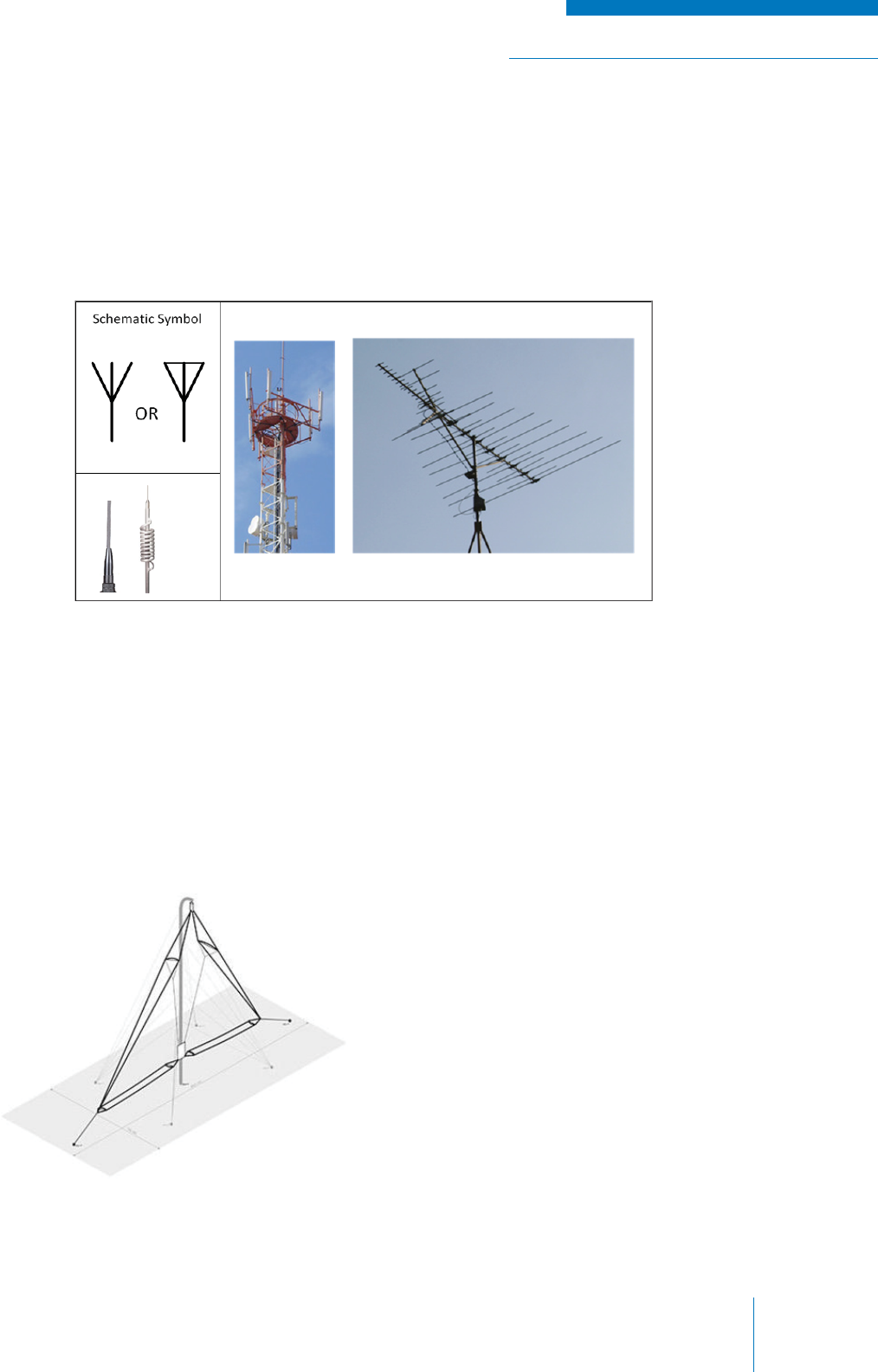
Figure 2-27: Antennas
Figure 2-28: Complex Antenna
The Antenna
Antennas can take many shapes, sizes and confi gurations depending on a number of factors, for
example (see Figure 2-27):
• wavelength of the signal that they will be transmitting (and/or receiving)
• power of the signal
• space available for their deployment
While this may seem complicated, antennas are essentially any type of conductor that is conducive
to transmitting a radio signal. An antenna is simply an electrical circuit that is open (i.e., disconnected
at a point from being a complete circuit), which is why the simplest antenna can be made of just one
(called a monopole) or two (called a dipole) pieces of wire.
The open in the circuit means that it has an impedance and VSWR of ∞ and while this usually is
a worst-case scenario in a circuit, in the case of an antenna its ideal. As an incident wave hits the
abrupt discontinuity, a portion of the energy is transferred into the air as an electromagnetic wave; the
rest is refl ected back and remains in the antenna as a standing wave and/or is dissipated as heat.
Many antennas are the size of a quarter-
wavelength or half-wavelength of the intended
signal to take advantage how a wave travels
within the antenna, thus
maximizing the transfer of energy into the air.
Recall that wavelength is inversely proportional
to frequency, so the lower the frequency, the
longer the wavelength and subsequently,
the antenna. For example; high frequency,
low power devices, such as cellular phones,
have tiny antennas built into the casing of the
phone, whereas lower frequency HF (skywave)
communications generally require very large
lengths of wire arranged on poles, such as the
one shown below (see Figure 2-28).
TRAINING GUIDE | RADIO SYSTEM BASICS & RF FUNDAMENTALS
Chapter 2: Basic Radio ElementsPage 34
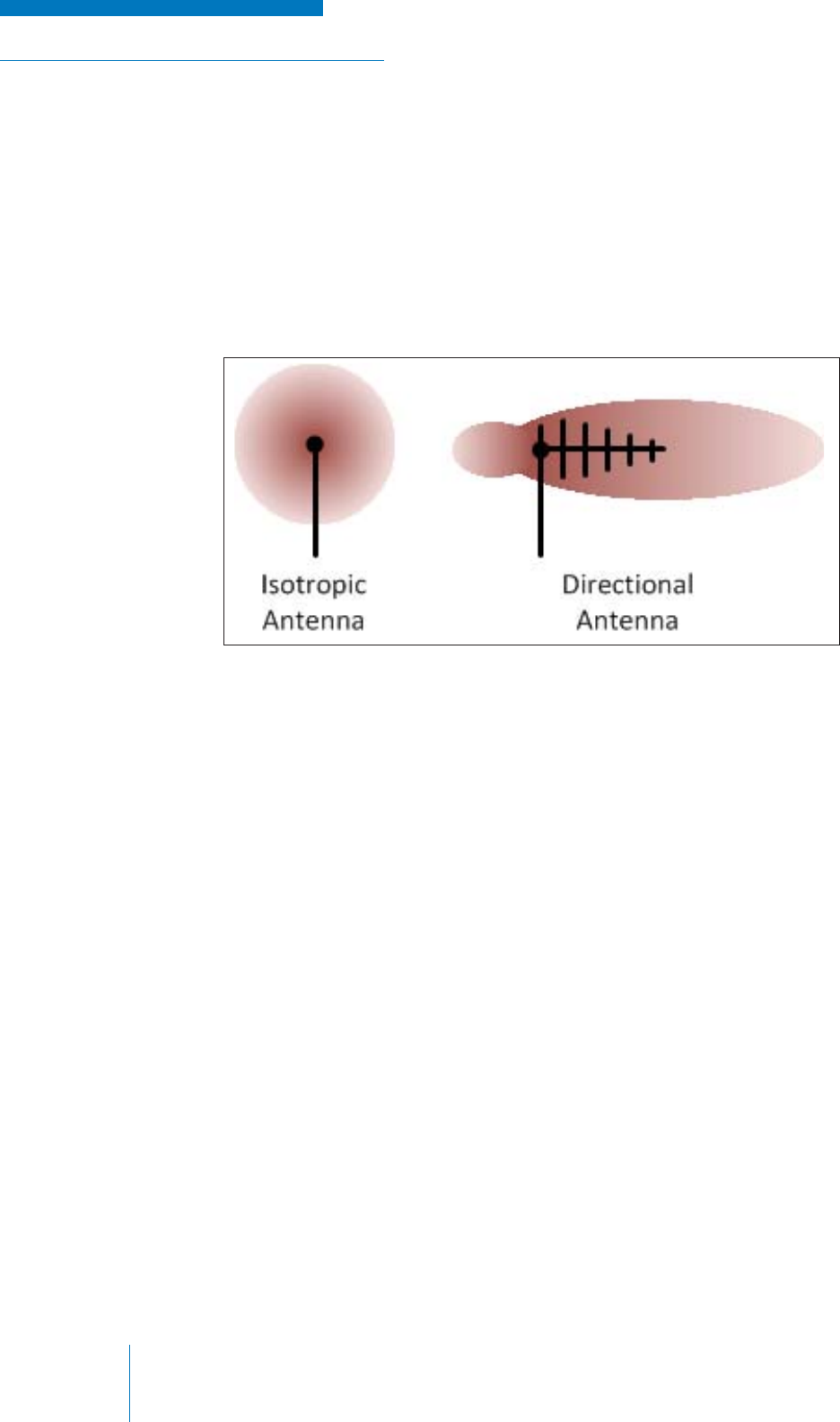
Figure 2-29: Antenna Plane Waves
Radiation and Antenna Gain
As the electromagnetic waves leave the antenna, they radiate out in all directions. One can imagine
the leading edge of the electromagnetic waves forming a single “surface” called the plane wave,
expanding out from the antenna in all directions like a balloon being rapidly fi lled with air. In the
simplest case, this expansion is uniform in all directions. An antenna that exhibits this behavior is
known as an isotropic antenna or omni-directional antenna. In many situations, however, the aim is
not to transmit in all directions, but in one direction in particular (see Figure 2-29). Using a directional
antenna, one can focus the electromagnetic energy so that more goes in the intended direction and
less in unwanted directions.
Focusing the radiation of the electromagnetic energy in a certain direction is known as gain. Although
the term ‘Gain’ is the same as is used in an amplifi er, an important distinction must be made. The
gain in an antenna does not actively increase the power transmitted like an amplifi er does, but rather
focuses more power in a particular direction at the cost of decreasing power in all other directions.
Therefore, when referring to gain in an antenna, it is a comparison as to how an isotropic antenna
radiating the same amount of power would perform, rather than any amplifi cation of the signal.
Antenna gain is expressed in decibels (dB); the logarithmic ratio of the output power of the directional
antenna relative to an isotropic reference antenna.
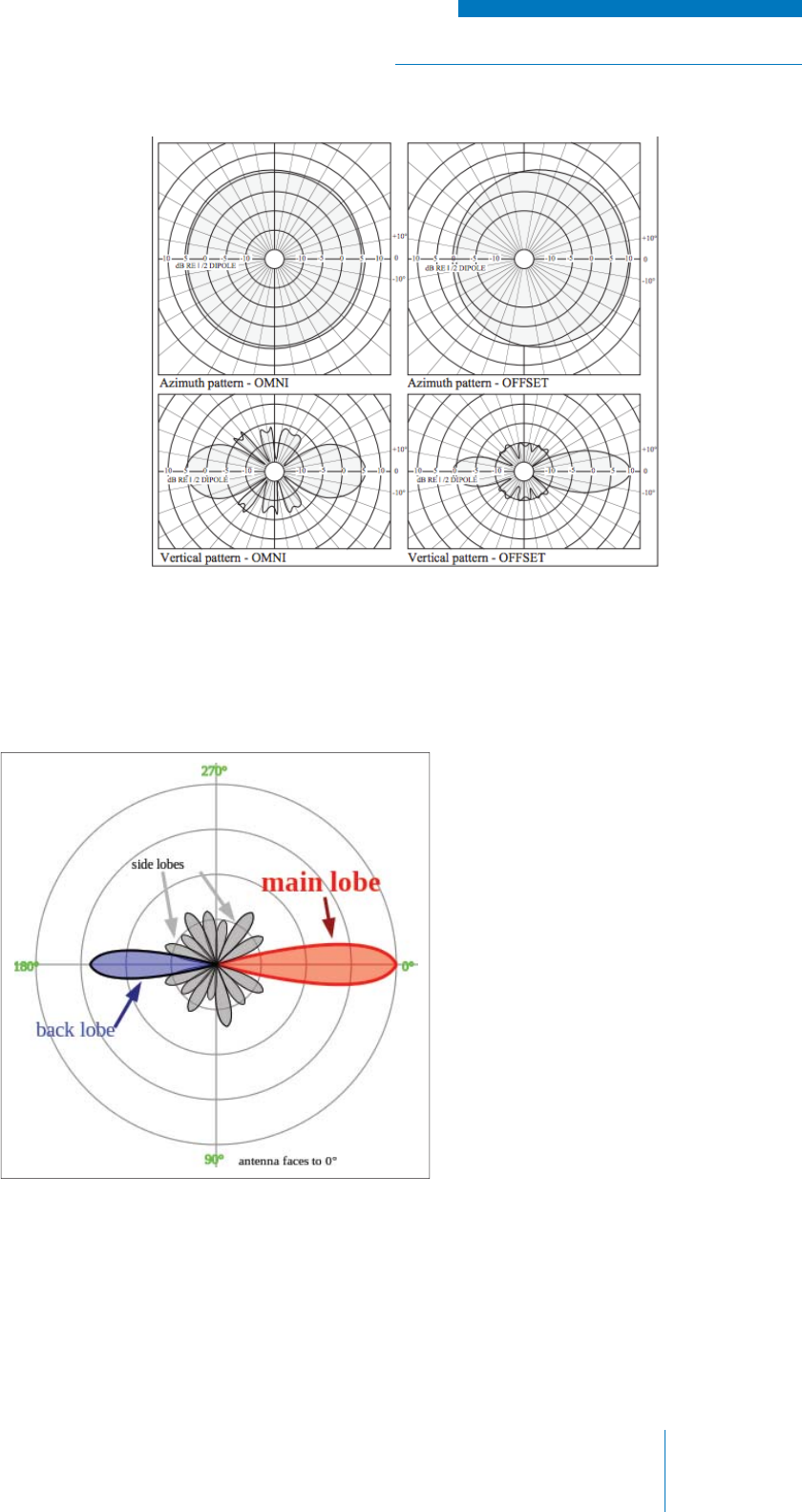
RADIO SYSTEM BASICS & RF FUNDAMENTALS | TRAINING GUIDE
Chapter 2: Basic Radio Elements Page 35
Figure 2-31: Antenna Lobes
Figure 2-30: Antenna Radiation Patterns
Elongated areas of directional antenna gain extending out from the antenna are known as lobes.
Even if an antenna is designed to have one purposeful main lobe, it will have an unintentional back
lobe (see Figure 2-31).
The gain of an antenna is often
shown on a chart known as a
radiation pattern; at the center point
of the chart is the antenna itself and
the line drawn around shows the gain
in all relative directions represented
by (polar) degrees. See Figure 2-30.
An antenna often has two or more
of these radiation pattern charts to
defi ne its operation, for example, a
horizontal one showing the ration
pattern as if one were looking at
the antenna from the top down and
a vertical radiation pattern is if one
were looking at the antenna from the
side.
Transmission
The transmission process is completed with the modulated RF carrier signal radiating from the
antenna into the transmission medium.
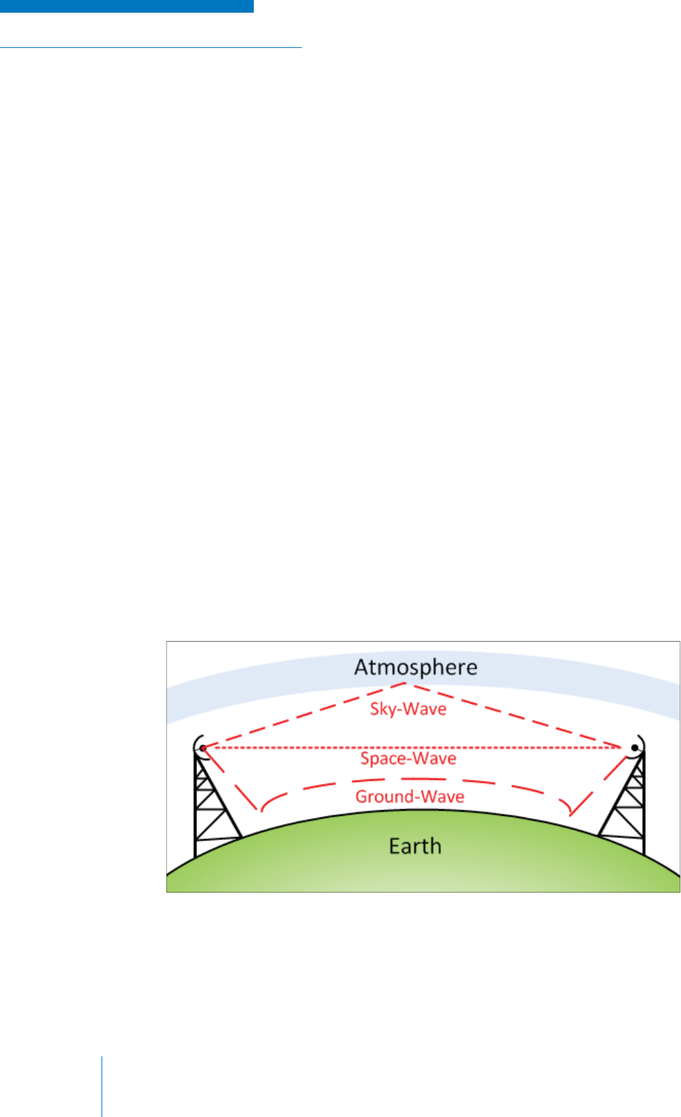
TRAINING GUIDE | RADIO SYSTEM BASICS & RF FUNDAMENTALS
Chapter 2: Basic Radio ElementsPage 36
Figure 2-32: Radio Wave Communications
PROPAGATION AND THE TRANSMISSION MEDIUM
The transmission medium can technically be anything an electronic communication signal passes
through to reach its destination, but since our topic is wireless communication, we will focus on how a
radio signal travels through the air to reach its destination at a receiver.
Propagation
The movement of radio waves through the air is called propagation and in free space (i.e.,
in a vacuum where nothing impedes movement) radio waves can travel at the speed of light,
approximately 3x10⁸ m/s.
Recall that the antenna on a transmitter sends out RF energy in all directions. Some radio waves
will travel straight parallel to the Earth’s surface; some will travel up and out in the direction of space;
some will travel down towards the surface of the Earth. When viewing radio communication from this
perspective, there are three categories that all types of radio communication can be grouped into:
• Space-Wave Communication: The typical scenario in which the transmitter and the receiver
are within a line-of-site (LOS) of each other (i.e., the operator of the transmitter can see
the receiver and vice versa) and the intended signal is sent straight through the air from
the transmitter to the receiver. Most terrestrial communications, including LMR, fall into this
category.
• Ground-Wave (Surface-Wave) Communication: Certain types of radio waves can travel
along the surface of the Earth, or more ideally, salt water, since the latter is a good conductor.
This form of radio communication is rarely used, though it has some application in marine
communications.
• Sky-Wave Communication: Radio waves are projected upwards and refl ected off of the
Earth’s atmosphere in order to achieve communication over very large distances that would
normally be impeded by the curvature of the Earth (see Figure 2-32).

RADIO SYSTEM BASICS & RF FUNDAMENTALS | TRAINING GUIDE
Chapter 2: Basic Radio Elements Page 37
In practical situations the environments in which radio waves propagate are not ideal, so there are
many factors that determine if a radio signal originating at the source transmitter can propagate
through the air and be received at its destination:
• Placement of the transmitter and receiver
• Frequency of the signal
• Power at which the signal is transmitted
• Nature of the terrain and atmosphere between the transmitter and receiver
• Obstructions between the transmitter and receiver
The Effect of Frequency on Propagation
The frequency and wavelength of the radio waves determines how far they can travel and how they
behave when they encounter an obstacle. Radio waves have a tendency to either ‘bounce off’ a
surface, or ‘pass though’ (be absorbed) a surface to varying degrees, depending on the frequency of
the signal. This behavior is also seen in visible light, which is also a form of electromagnetic energy.
Because of this, the frequency band one chooses for their radio system must not only adhere to cost
and regulatory constraints, but must also be suited for the terrain in which the system is to be used,
and the distance which it must cover.
As the frequency of a radio signal increases, the less the radio wave refl ects off of surfaces and the
more it is absorbed by surfaces. As such, the higher the frequency of a communication system, the
lower the range. Once again, thinking in terms of other common forms of electromagnetic energy is
useful for remembering this concept. Visible light has a frequency in the 1014 Hz range and refl ects off
the skin, whereas x-rays (another form of electromagnetic energy) are higher in frequency at 1018 Hz
and pass easily through one’s skin, allowing doctors to take pictures of a person’s bones.
Absorptive properties of radio signals are damaging to the range of radio signals. Where lower
frequency signals are more likely to bounce around and eventually reach their destination, higher
frequency signals will simply be absorbed by the terrain and/or the air itself and be lost altogether; this
is called absorption loss. As a general rule, the higher the frequency that a radio system operates at,
the lower the distance that its signals can travel.
Refl ective properties of radio signals (including refraction, diffraction, and scattering) can either
impede or assist communications. Sky-wave communication systems use the fact that HF (3 MHz
to 30 MHz) radio signals can refl ect and refract off of the Earth’s ionosphere to overcome obstacles
(such as the curvature of the Earth) to achieve communication over large distances. Space-wave
communications can utilize natural or man-made refl ective surfaces within the terrain to reach
receivers that are outside of the LOS. Conversely, space-wave transmissions are also often impeded
by properties of radio signals, since the intended signals can be kept from reaching their intended
destination by refl ecting in an unwanted direction or by being absorbed by an obstructing surface.
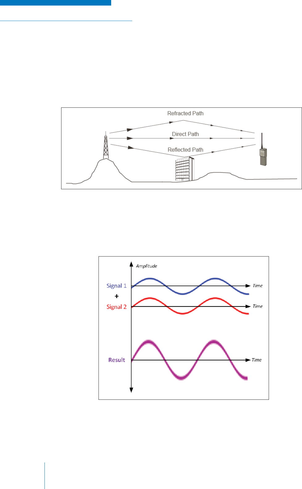
TRAINING GUIDE | RADIO SYSTEM BASICS & RF FUNDAMENTALS
Chapter 2: Basic Radio ElementsPage 38
Figure 2-33: Radio Signal Paths
Figure 2-34: In-Phase Signals
Addition of Signals and Multi-Path Loss
Another destructive effect due to the refl ective properties of radio signals is called multi-path loss,
in which refl ected signals arrive at the destination receiver slightly delayed in relation to the direct
intended signal because they took a less direct path (see Figure 2-33). When this happens, the direct
signal and the delayed refl ected signal have a tendency to cancel each other out, thus weakening
or distorting the received transmission. Conversely, if the signals arrive at the exact same time, the
effect is not destructive, but rather an overall strengthening of the signal.
This effect can be understood more easily if one considers two radio signals appearing in the same
place as sinusoids that are being added together (see Figure 2-34). If two signals arrive at the same
time, their sinusoidal phases match; in this situation, the signals are called in-phase. When added
together mathematically, this results in the same sinusoidal shape but with a greater magnitude.
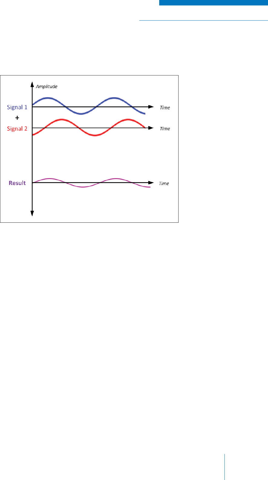
RADIO SYSTEM BASICS & RF FUNDAMENTALS | TRAINING GUIDE
Chapter 2: Basic Radio Elements Page 39
Figure 2-35: Out-of-Phase Signals
If two signals arrive at different times, their sinusoidal phases differ and are said to be out-of-phase
(see Figure 2-35). When added together mathematically, the result can range from a distorted or
diminished signal to complete cancellation (180° out-of-phase).

TRAINING GUIDE | RADIO SYSTEM BASICS & RF FUNDAMENTALS
Chapter 2: Basic Radio ElementsPage 40
Equipment Placement, Terrain and Power
Just like a person’s voice, as a radio signal travels through the air, it loses intensity due to absorption
loss and attenuation—which is the reduction in power density the further it is from its source (think of
a light getting dimmer the further away you are). Eventually, if enough total loss occurs, the receiver
cannot distinguish the signal. All of the losses that cause a signal to lose intensity are collectively
known as path loss.
Terrain can also have a profound effect on how a radio signal travels to its intended destination.
Ideally, the receiver and transmitter would be in line-of-site with each other without any obstructions
in between; in reality however, the space in between a transmitter and receiver is often fi lled with
buildings or mountains that block signals, or shiny surfaces such as leaves, water or windows that
refl ect and refract them.
The quality of the air can be considered an invisible part of the terrain, as the amount of moisture in
the air affects how much of the signal is absorbed. At a great enough distance the curvature of the
Earth itself becomes an insurmountable factor in terms of terrain.
The challenge of distance, terrain and frequency effects in a radio communications link are often
solved by a combination of the following:
• Increasing the power of the transmitted signal to overcome path loss and accommodate for
technical limitations of the receiver
• Re-positioning of the radio equipment, particularly the antennas of the transmitter and
receiver to convenient locations, for example, raising the antennas higher to overcome
obstacles in the terrain
Sometimes line-of-sight communications are impossible because the terrain is simply too diverse,
or the technical / regulatory limitations don’t allow for increases in power or the use of convenient
frequencies. Thankfully, there are creative ways to get around this problem. For example, when
the curvature of the Earth itself becomes a physical obstacle at large distances, one can use HF
frequency sky-wave communication to refract signals off of the Earth’s atmosphere to reach receivers
that are beyond the line-of-sight of the transmitter. In a later section of this manual, we will also
explore how the arrangement or addition of more / various types of radio equipment can be used to
create multiple radio links that overcome obstacles that would be insurmountable for a single link.
The challenge in designing a radio communication link can therefore be summarized as ensuring that
the signal radiated (or directed) at the receiver is high enough in power and positioned adequately to
account for:
• total path loss at the given frequency and terrain
• technical limitations of the receiver (see the “Reception” section).
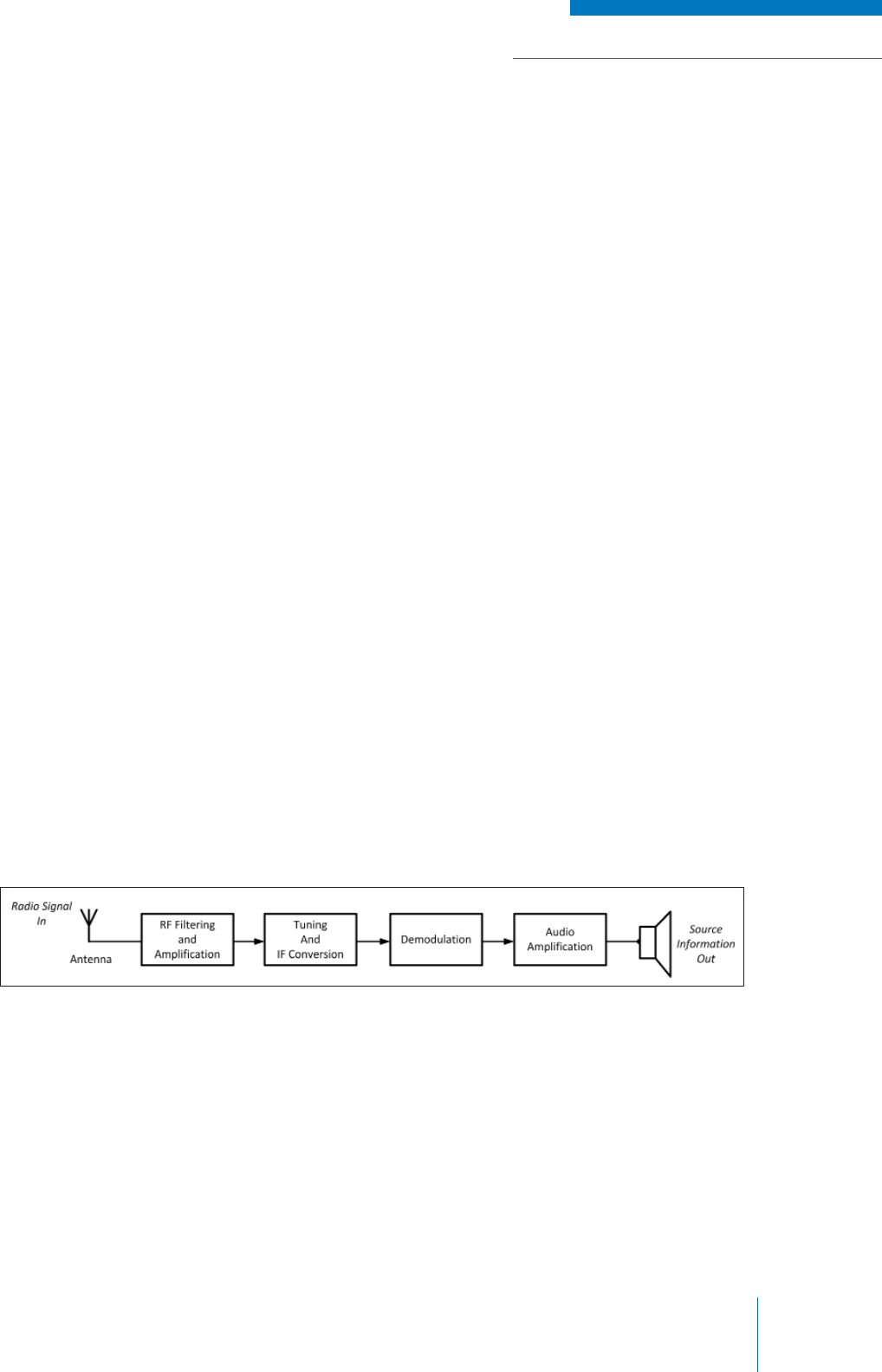
RADIO SYSTEM BASICS & RF FUNDAMENTALS | TRAINING GUIDE
Chapter 2: Basic Radio Elements Page 41
Figure 2-36: Receiver Operations
RECEPTION
After the radio signal travels through the air, it reaches its intended destination, the receiver, which is
a piece of electronic equipment that converts the RF signal back into an audio (or other intelligible)
signal, so the signal can be interpreted by the listener (a person or computer). In essence, the
receiver simply does the reverse of what a transmitter does.
A receiver’s performance is defi ned by how well it can discern the intended radio signals from all
other RF signals and noise in the air. Receiver performance characteristics fall into three categories:
1. Sensitivity: How small / weak the intended signal can be before the receiver is no longer
able to discern it. Sensitivity characteristics of a receiver are often defi ned by seeing how
strong the intended signal must be compared to the noise in the system while still remaining
intelligible.
2. Selectivity: How well the receiver can discern the intended signal from other unwanted
signals that differ in frequency.
3. Fidelity: How well the receiver can reproduce the original audio (or other intelligible) signal.
There are many different types and variations on receiver design. While not the simplest, the
most commonly used for both AM and FM / PM is the superheterodyne design which has superior
selectivity and sensitivity characteristics.
Although receivers are often complex electronic devices with many different variations on design,
their operation can be summarized by six basic functional stages that are found in most devices:
1. Antenna
2. RF Filtering and Amplifi cation
3. Tuning and IF Conversion
4. Demodulation
5. Information Signal Conditioning (AF Amplifi cation or Data Processing)
6. Output
The block diagram below outlines these stages (see Figure 2-36).
The elements of the receiver are detailed further in following sections.
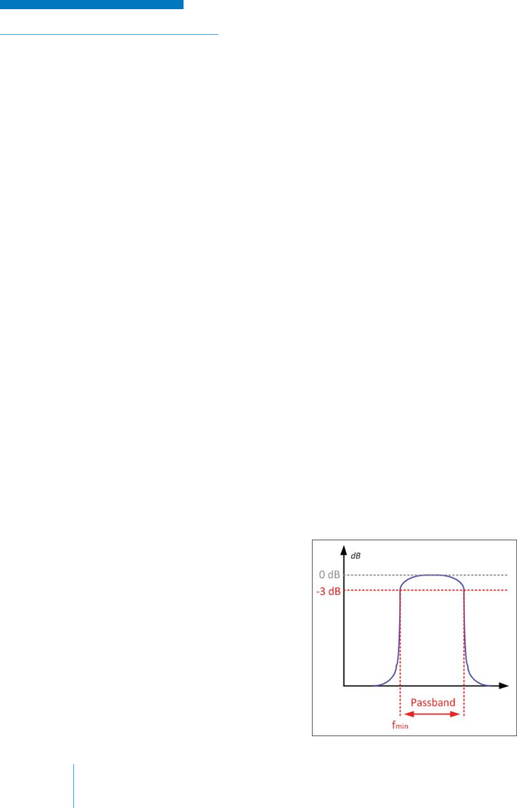
TRAINING GUIDE | RADIO SYSTEM BASICS & RF FUNDAMENTALS
Chapter 2: Basic Radio ElementsPage 42
Figure 2-37: Bandpass Filtering
Antenna
The antenna that is found on the receiver is often very similar (if not completely the same) to the
antenna on the transmitter; that is, it is a piece of conductive material with dimension and orientation
characteristics chosen to suit the radio frequency of interest. When the antenna is in the presence
of an EM fi eld consisting of radio signals falling within the correct range of frequencies, the signal
induces an electric current within the antenna that varies in time and amplitude with the radio signal.
This current travels through the cable connecting the antenna to the receiver.
RF Filtering and Amplifi cation
Often (but not always), the fi rst set of electrical components the received RF signal will pass through
with be a Front End (RF) fi lter.
RF Filters
An RF fi lter is an important piece of radio equipment that consists of electrical components such as
resistors, inductors and capacitors that are confi gured to resonate at a certain range of frequencies.
That is, the impedance characteristics become optimal when the correct range of frequencies is
applied. Signals with frequencies that fall within the range of resonant frequencies are either passed
or rejected depending on the type of fi lter and what it is used for. Any frequencies that fall outside of
this range are rejected or passed conversely.
Resonance at the desired frequencies is achieved by varying the values of the electrical components;
this is known as tuning the fi lter circuit. RF fi lters range in size from small integrated circuits to
extremely large external equipment, depending on the application.
The Front End fi lter is generally an internal circuit within the receiver and is confi gured to pass a
range of resonant frequencies and reject everything else; this type of fi lter is known as a Bandpass
fi lter. The range of frequencies that the fi lter resonates with is therefore known as the passband and
all received electrical signals having frequencies that fall within this range are passed onto the next
part of the receiver.
Note that the passband for a Front End fi lter is generally quite wide and additional fi ltering is required
to block all of the undesired signals. This fi ltering is done to exclude any unwanted signals that may at
the very least interfere and/or distort with the information that is intended for the listener and, at worst,
damage the receiver itself. How well the fi lter
can pass the desired signal and reject undesired
signals has a great effect on the selectivity and
sensitivity performance of the receiver.
The bandwidth of the pass band of the fi lter is
defi ned between the points where the amplitude
of the signal is decreased by 3 db.
The diagram (see Figure 2-37) shows what a
bandpass fi lter’s output would look like in the
frequency domain if one were to input a signal of
uniform amplitude, but “sweeping” incremental
frequency (this is known as a frequency
response).
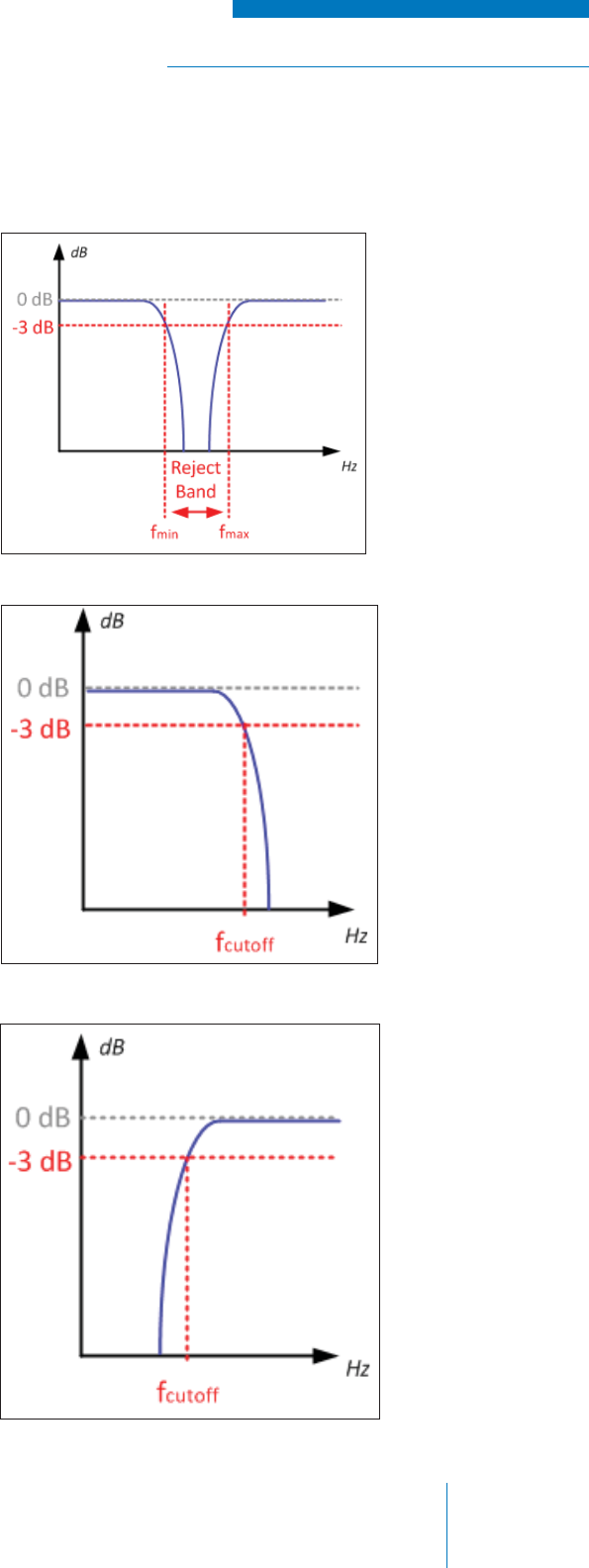
RADIO SYSTEM BASICS & RF FUNDAMENTALS | TRAINING GUIDE
Chapter 2: Basic Radio Elements Page 43
Figure 2-38: Band Reject Filters
Figure 2-39: Low Pass Filters
Figure 2-40: High Pass Filters
In other applications, fi lters can be designed to suit other particular frequency rejection requirements:
• Low Pass: All signals above a
defi ned frequency are rejected,
while frequencies below this
point (down to 0 Hz) are passed;
this point is known as the cutoff
frequency (See Figure 2-39)
• High Pass: All signals below a
defi ned cutoff frequency are rejected
(see Figure 2-40)
• Band Reject: The opposite of a
bandpass, where all frequencies
are passed except for a selected
range (see Figure 2-38)
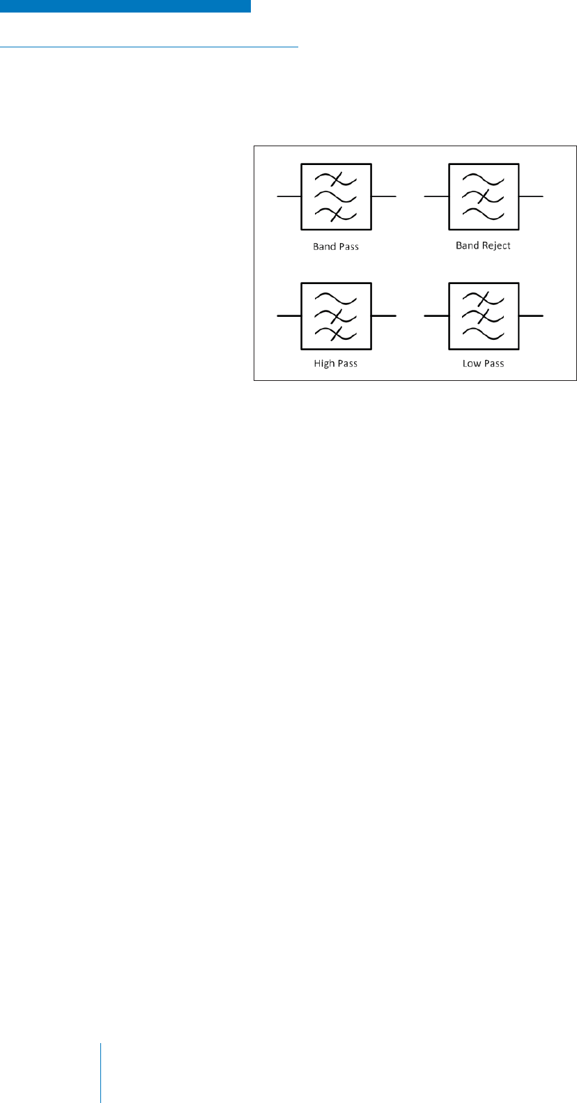
TRAINING GUIDE | RADIO SYSTEM BASICS & RF FUNDAMENTALS
Chapter 2: Basic Radio ElementsPage 44
Figure 2-41: Schematic Symbols for Filters
Filters are usually comprised of a number of electronic elements, but the following generalized
symbols are used to represent a fi lter in functional diagrams (see Figure 2-41).
RF Amplifi er in the Receiver
By the time a radio signal is received by the receiver, it is likely very low in power and therefore must
be amplifi ed to a usable level; for this an RF amplifi er is used. The amplifi er will operate similarly to
RF amplifi er found in the transmitter, but at much lower power, since the signal does not need to be
transmitted over large distances.
In addition to increasing the signal strength of the received signal, the amplifi er performs additional
fi ltering by only amplifying signals within a narrow frequency range, thus eliminating some of the
undesired signals that may have passed through the Front End fi lter.
Tuning and IF Conversion
Next, the received, amplifi ed and fi ltered received RF signal (which still contains the desired
information) is usually converted to an Intermediate Frequency (IF) signal; this is done to facilitate
exact selection of the desired RF frequency while allowing most of the radio electronics to remain
fi xed in value and operation, even if the desired reception frequency is changed.
The IF frequency itself is usually a fi xed frequency that is common in all devices regardless of
manufacturer, but dependent on application and receiver operation. Standard IF frequencies for FM
radios, for example, include 21.4 MHz or 455 MHz.
The RF signal is frequency mixed with a Local Oscillator (LO) signal to produce the IF signal. Since
this process is mathematical, only a specifi c RF frequency and specifi c LO frequency will produce the
required IF frequency. The LO frequency is therefore varied, thereby allowing the user to select which
exact RF frequency is received. This varying of the LO to select the desired RF frequency is called
tuning.
Sometimes there is more than one IF conversion in a receiver, each progressively lower in frequency.
This is done for various reasons, but chiefl y because lower frequencies are easier and cheaper to
work with on an electronics level. The IF signal is usually amplifi ed as well, once again to make it
easier to work with in the demodulation stage that follows.

RADIO SYSTEM BASICS & RF FUNDAMENTALS | TRAINING GUIDE
Chapter 2: Basic Radio Elements Page 45
Demodulation
Although the received signal is now been converted to a lower frequency signal in the IF stage, the
signal still consists of two components: the higher IF frequency carrier signal and the information
signal that we wish to extract. The detection circuits in a receiver perform the opposite function of
the modulation process in the transmitter; they remove the IF frequency leaving only the information
signal through a process called demodulation.
The exact nature of the demodulation process varies depending on the type of modulation the
receiver is designed to work with. In AM, for example, the demodulation process involves keeping the
envelope shape signal and removing the high frequency components. Alternately in FM (and PM),
the changes in frequency are converted to a low frequency information signal. In either case, the high
frequency components are removed leaving only the original information signal.
In a receiver that is used for a digital radio application, the demodulation process detects the digital
modulation to produce a stream of bits that are processed into an intelligible form of information in the
fi nal stage of the reception process.
Information Signal Output
The only thing that remains is to output the information signal to the user to complete the process of
radio communication.
In an analog audio application, the AF signal is amplifi ed to the desired level and output through a
speaker, headphones or other. Like the microphone but reversed in operation, the speaker is simply
a device that converts electrical voltages to vibrations in the air that can be heard by a person.
If pre-emphasis was applied to the audio prior to transmission, the reverse process, known as
de-emphasis, is performed prior to output as audio.
In a digital application, the bitstream is processed by computing circuitry to produce some sort
of useable output, such as audio, visual information on a screen or control information for other
electronic devices to use.
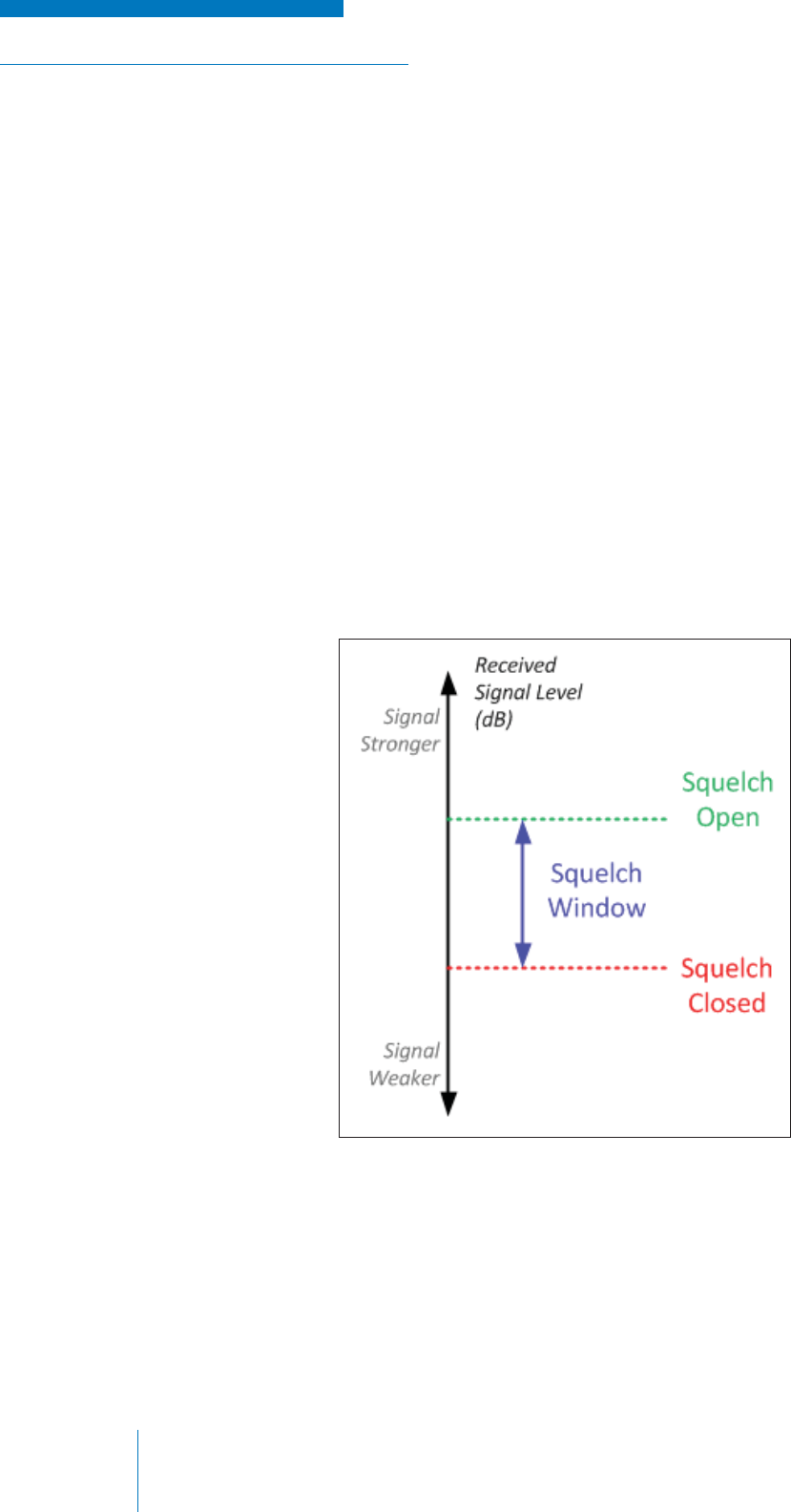
TRAINING GUIDE | RADIO SYSTEM BASICS & RF FUNDAMENTALS
Chapter 2: Basic Radio ElementsPage 46
Figure 2-42: Squelch Operations
Squelch
If one listens to the audio coming from a receiver when there is no signal being transmitted, one
will hear random noise (known as white noise) that is caused by various natural and man-made
electromagnetic phenomenon in the air. Needless to say, listening to this noise the entire time that the
receiver is on is undesirable, but a receiver must remain on in order to “listen” for any transmissions
that may occur.
A squelch circuit solves this problem by muting the audio that comes out of the radio until a carrier
signal of suffi cient strength is detected. This means that the user is spared listening to noise, but the
receiver can still “listen” for a signal and the audio circuits activate when there is something to listen
to. The action of the audio being turned off is commonly referred to as squelching or closing of the
squelch circuit.
Unsquelching is the opposite operation; it is when audible reception is enabled at the presence of a
suffi ciently strong signal (or control signal, as will be shown in a later section). The action of the audio
being turned off is commonly referred to as unsquelching or opening of the squelch circuit.
Unsquelching is usually set to occur at a higher signal level than the signal at which the squelch
closes; this avoids the audio rapidly turning on and off. The difference between the squelch opening
and closing points is known as the squelch window (see Figure 2-42).
RADIO SYSTEM BASICS & RF FUNDAMENTALS | TRAINING GUIDE
Chapter 3: Radio Systems Page 47
CHAPTER 3: RADIO SYSTEMS
RECEIVERS AND TRANSMITTERS IN A SYSTEM
Up to this point we have examined the basic elements of a radio communications system and how
they interact in the simplest arrangement: a single piece of equipment that transmits a signal, and
a single piece of equipment that receives a signal. It has been established that this arrangement is
susceptible to interference, is limited in its range and is heavily impacted by the terrain in which it is
established.
At this point, it is convenient to think of the receiver and transmitter to be the “building blocks” of a
radio communications system, which can be added and arranged to provide required functionality and
to overcome the previously mentioned limitations that are again summarized below:
• Equipment placement limitations
• Distance between receiver and transmitter
• Blocking / interfering terrain
• Antenna height / space requirements
• Equipment technical (and/or regulatory) limitations
• Transmission power
• Receiver sensitivity
• Frequency availability / allocations

TRAINING GUIDE | RADIO SYSTEM BASICS & RF FUNDAMENTALS
Chapter 3: Radio SystemsPage 48
Radio System Terminology
The words used in radio communications can become cumbersome when describing receiver and
transmitter operation in a radio system with many elements. This is particularly evident when one tries
to plan a radio communications system graphically. To solve this, simplifi ed terms and symbols are
used to replace lengthier words and terms. Some key examples of this are listed below:
• A receiver or the act of signal reception is often shortened to ‘RX’
• A transmitter or the act of transmitting a signal is often shortened to ‘TX’
• Frequency is often shortened to the lowercase letter ‘ƒ’, with the descriptor of the frequency
stated in subscript afterward.
For example:
• In a system that uses a single receive frequency of 150 MHz, this can be stated as:
ƒRX = 150.000MHz
• In a system that uses a single transmit frequency of 150.5 MHz, this can be stated as:
ƒTX = 150.500MHz
• In a system that uses multiple frequencies (e.g., 150 MHz, 150.5 MHz, 151 MHz) for
receiving or transmitting, these can be stated as:
ƒ1 = 150.000MHz
ƒ2 = 150.500MHz
ƒ3 = 151.000MHz
…
Note that in this case, the direction (i.e., whether the frequency is being used to receive or
transmit) would be shown graphically or stated otherwise.
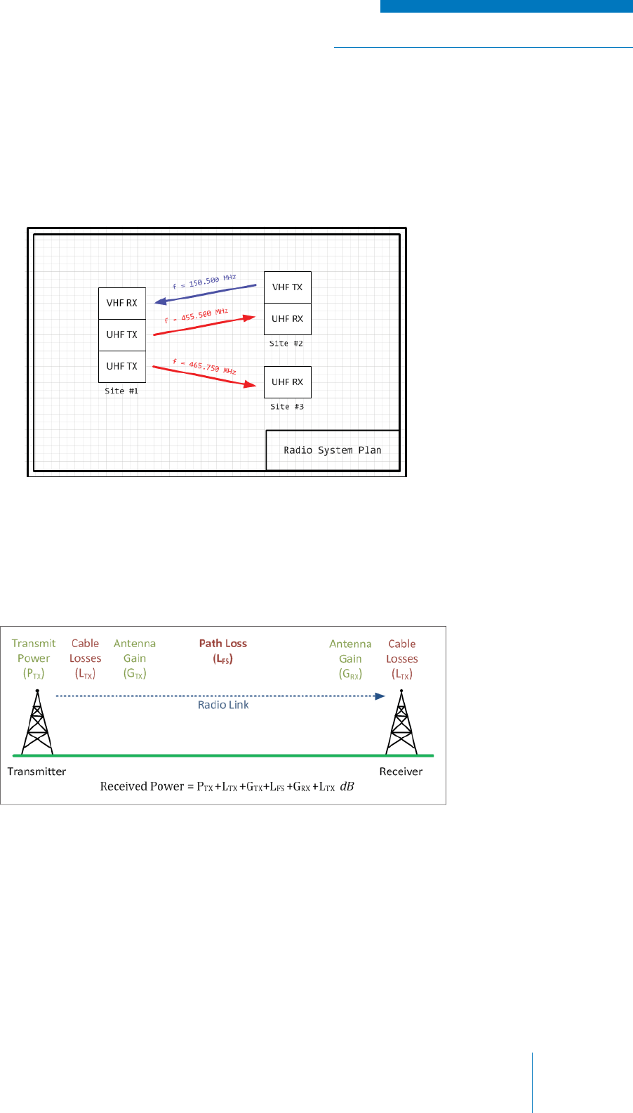
RADIO SYSTEM BASICS & RF FUNDAMENTALS | TRAINING GUIDE
Chapter 3: Radio Systems Page 49
Figure 3-1: Communications Plan
Figure 3-2: Link Budget Diagram
System Diagrams
System diagrams are helpful in understanding how a radio system with multiple links works and are
useful tools to use when planning a radio system. These may range in complexity from a simple block
diagram listing equipment and frequencies, to a geographically accurate map indicating coverage,
detailed equipment information and more. A top-down view diagram as shown below is the simplest
form of planning diagram (see Figure 3-1).
Another type of planning tool that is often used is called a link budget. This diagram (see Figure 3-2)
outlines all of the losses and gains for a single link—from the source to the receiver for the purpose of
mathematically adding all of the gains and subtracting all of the losses (in decibels), to estimate if the
signal that is to reach the recipient is strong enough.
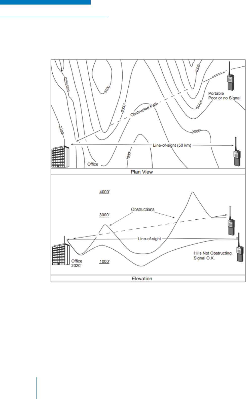
TRAINING GUIDE | RADIO SYSTEM BASICS & RF FUNDAMENTALS
Chapter 3: Radio SystemsPage 50
Topographic and path profi le maps can be used to add further detail on how coverage will be affected
by terrain in a system plan (see Figure 3-3).
Figure 3-3: Examples of Topographic Design Maps
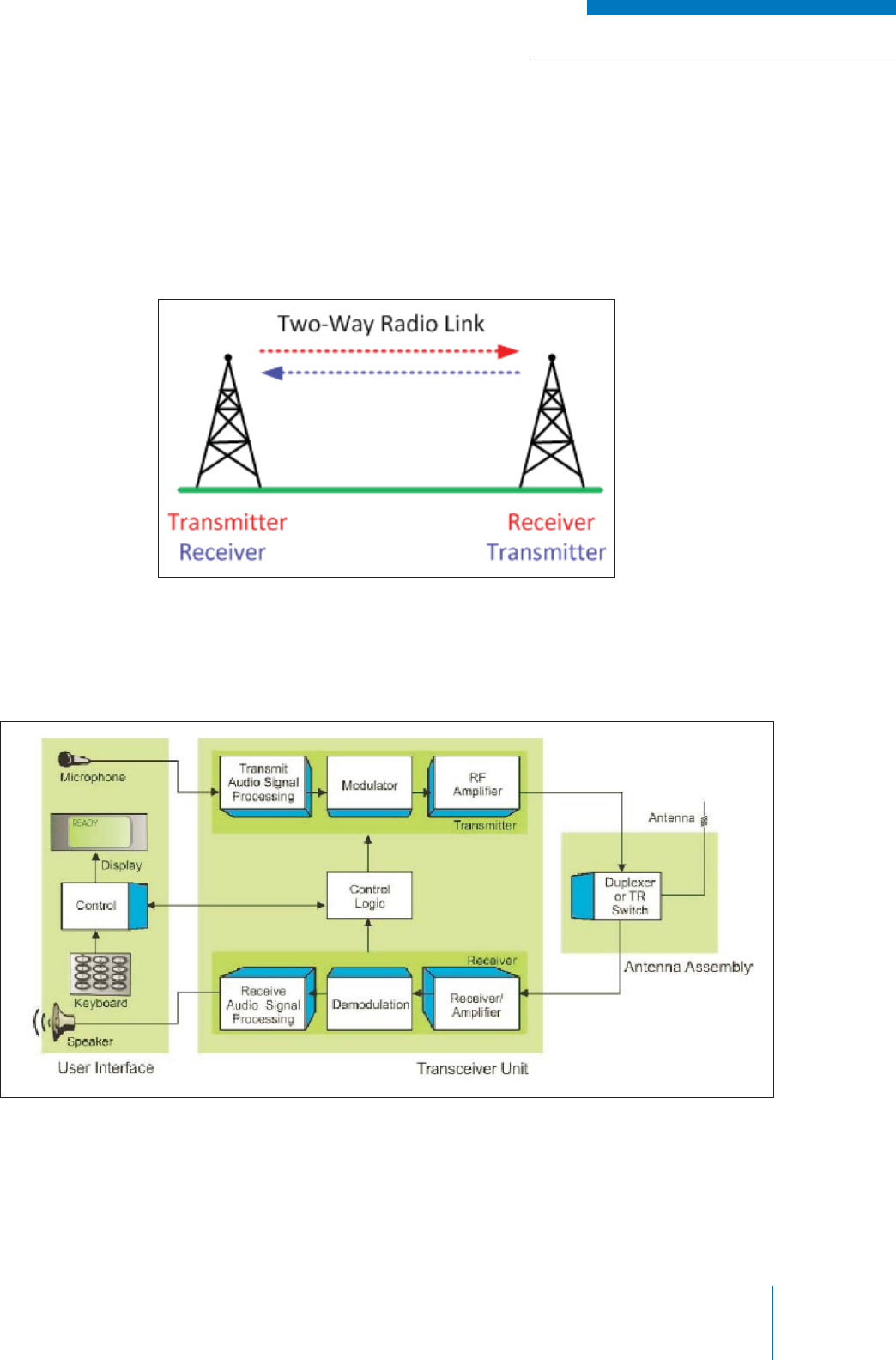
RADIO SYSTEM BASICS & RF FUNDAMENTALS | TRAINING GUIDE
Chapter 3: Radio Systems Page 51
TRANSCEIVERS AND EQUIPMENT CO-LOCATION
In looking at the simple radio arrangement of a transmitter and a receiver, one might ask “what if the
person at the receiver needs to communicate back to the person at the transmitter”? In this scenario,
it is convenient to have a single piece of radio communication equipment that can perform both
receiving and transmitting functions, so that the two users in the arrangement can easily switch roles
from transmitter to receiver. See Figure 3-4.
Figure 3-4: Two-Way Linking
Figure 3-5: Transceiver Equipment
A single piece of radio communications equipment that can both receive and transmit is known as a
transceiver (see Figure 3-5).
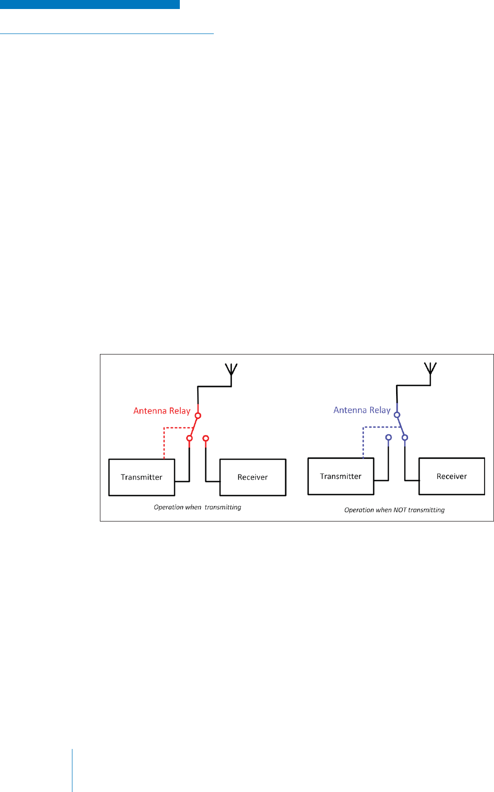
TRAINING GUIDE | RADIO SYSTEM BASICS & RF FUNDAMENTALS
Chapter 3: Radio SystemsPage 52
While combining the receiver and transmitter in a single unit is convenient, it does pose some
technical challenges. Positioning a transmitter directly beside a receiver poses a risk of too much
radio energy going into the receiver and damaging the equipment; this can be thought of the radio
equivalent to putting a loudspeaker right next to someone’s ear. There are a few ways to deal with
this issue that can be used separately or in combination:
• Separate the receiver and transmitter suffi ciently in frequency – ideally this separation must
be large, such as operating in two different bands altogether
• Add a fi lter to the input of the receiver to block out the operating frequency of the transmitter
• Separate the transmit and receive antennas by a large vertical distance
This last point is most often not possible because of special restrictions and because quite often
transceivers only have one antenna that both the receiver and transmitter share. This latter case is
desirable because of savings on materials and space, however the sharing of an antenna between
a receiver and a transmitter poses a technical challenge that must be addressed using additional
equipment, such an antenna relay or a duplexer.
Antenna Relay
When transmission and reception is not required to be simultaneous, an electrically activated switch
known as an antenna relay can switch the input of the antenna to the transmitter when the transceiver
is transmitting; otherwise the antenna is connected to the receiver (see Figure 3-6).
Figure 3-6: Shared Antenna Relay
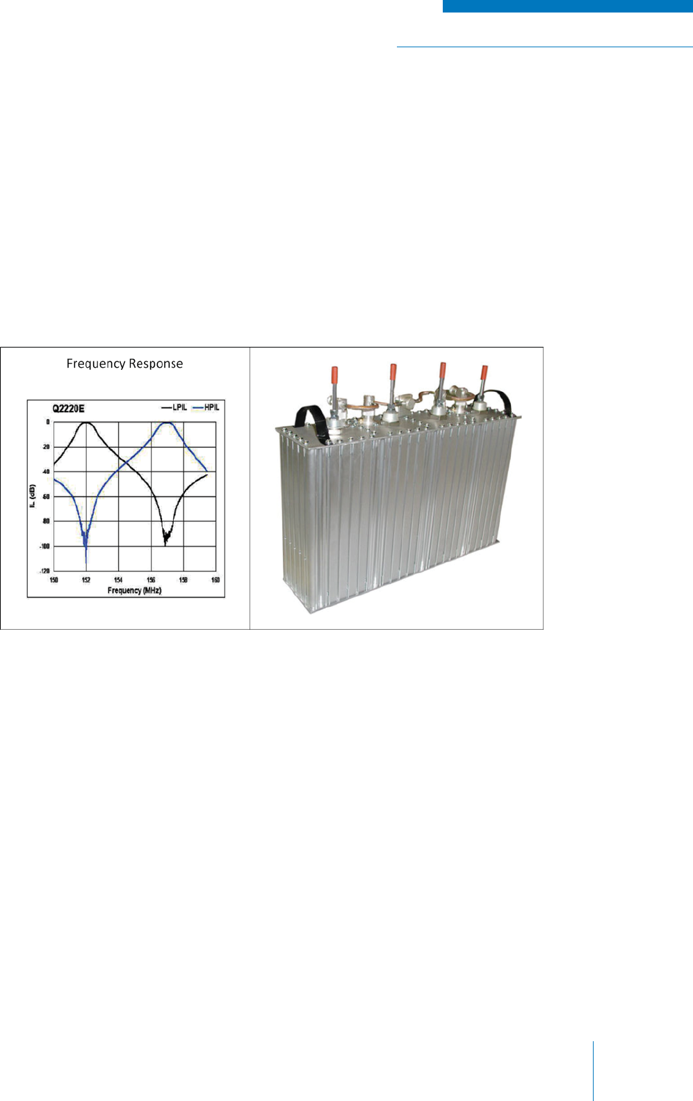
RADIO SYSTEM BASICS & RF FUNDAMENTALS | TRAINING GUIDE
Chapter 3: Radio Systems Page 53
Duplexers
A duplexer is a piece of equipment that allows a receiver and transmitter to share a single antenna.
Unlike an antenna relay, which only allows either the receiver or transmitter to use the antenna at
any given time, a duplexer allows both devices to operate simultaneously using the same antenna
provided that the receive and transmit frequency are suffi ciently different.
Duplexers are large external RF fi lters that are designed to reject / block the transmitter frequencies
at the receiver input, but pass all of the other frequencies, particularly those to which the receiver is
tuned to receive.
The diagram below (see Figure 3-7) shows the frequency response of a duplexer; that is how it
responds to a signal of constant amplitude that is swept across all frequencies of interest. Note that at
the tuned frequency, any signal with that frequency is blocked.
Figure 3-7: Example – Duplexer and Frequency Response
Selecting a duplexer for a radio application is a careful balance of the following six elements:
1. Frequency Band / Frequency Range: the range of frequencies that the duplexer can
operate in. Note that the duplexer is tuned to specifi c receive and transmit frequencies within
this band.
2. Frequency Separation: the difference in frequency between the receiver and transmitter
measured in Hertz.
3. Power Requirement: the maximum amount of RF power that will be transmitted into the
duplexer measured in Watts.
4. Insertion Loss: the amount of power that will be lost from the output of the transmitter to the
output of the duplexer measured in decibels.
5. Isolation: the amount the receiver input is isolated from the transmitter output measured in
decibels.
6. Physical Space Allowance: the size of the duplexer unit and how it fi ts within the physical
constraints of the installation.
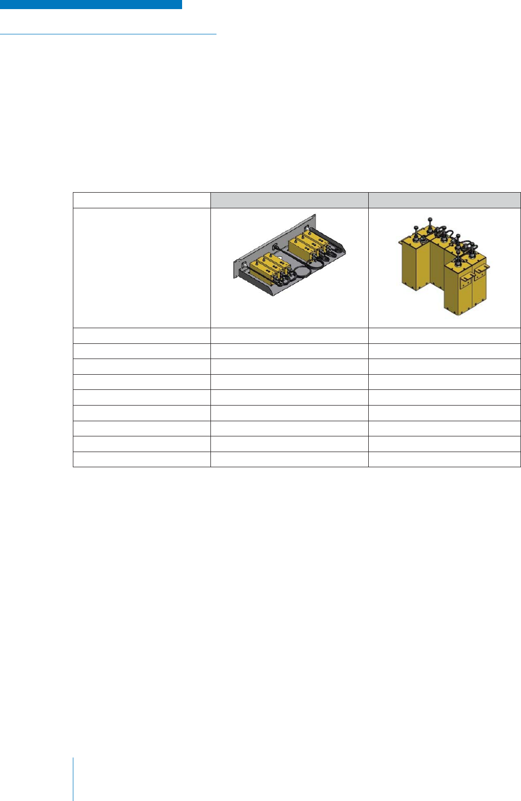
TRAINING GUIDE | RADIO SYSTEM BASICS & RF FUNDAMENTALS
Chapter 3: Radio SystemsPage 54
All of these elements are interconnected and having a strict requirement for one element will
most likely mean a compromise for another element. For example, the physical size (and cost)
of the duplexer can increase greatly with more stringent separation, power and frequency band
requirements; and one must be careful to allow enough room to accommodate the equipment.
The table below shows an example of how much size can increase when one or more of the elements
(in this case power requirement, insertion loss and isolation) are varied due to requirements.
See Table 7.
Table 7: Duplexer Size Comparison
DUPLEXER ‘A’ DUPLEXER ‘B’
Band: T-Band T-Band
Frequency Range: 470-512 MHz 470-512 MHz
Maximum Power: 100W 350W
Minimum TX/RX Separation: 3 MHz 3 MHz
Insertion Loss: 1.8 dB 1.6 dB
Isolation: 75 dB 85 dB
Height: 3.5 inches 8 inches
Width: 19 inches 19 inches
Depth: 8.84 inches 15 inches
*Images Courtesy of Comprod
Duplexers must be carefully tuned before use and care must be taken not to physically alter the
duplexers confi guration once its set. For example, large duplexers have ‘plunger’ type adjustments
that must be carefully positioned for correct operation. Unfortunately, these adjustments are often
bumped and mishandled after a radio system has been installed, potentially causing improper
operation and damage.
MODES OF COMMUNICATION
We have established that radio equipment can transmit, receive or perform an alternating or
simultaneous combination of both. These equipment capabilities defi ne how pieces of equipment
interact with one another in a radio system. To understand this better, one can think of system
elements in terms of mode of communication.
Unfortunately, the terminology used in describing communication modes is often confusing,
because the same terms are used to describe different aspects of a radio (and general electronic)
communications system. This confusion is also increased due to varying usage between different
individuals and organizations. Two aspects that are often referred to in terms of mode are equipment
operation and channel direction.

RADIO SYSTEM BASICS & RF FUNDAMENTALS | TRAINING GUIDE
Chapter 3: Radio Systems Page 55
Equipment Mode
Equipment operation can be categorized in terms of reception and transmission capabilities using the
following four mode types:
1. RX/TX Only
2. Simplex
3. Half Duplex (or ‘Two-Frequency Simplex’)
4. Full Duplex (or simply ‘Duplex’)
The commonly used defi nitions outlined below (see Table 8) apply to the characterization of radio
communications equipment.
Table 8: Radio Communications Equipment Defi nitions
RX/TX Only Simplex Half Duplex Full Duplex
Operation Can perform
receive or
transmit
function only
Can perform either
receive or transmit
functions, but not
simultaneously
Can perform either
receive or transmit
functions, but not
simultaneously
Can perform
both receive or
transmit functions
simultaneously
Frequency Single operating
frequency per
channel
Single operating
frequency per
channel – the
receive and transmit
functions share a
single frequency
Different operating
frequencies for
receive and transmit
functions
Different operating
frequencies for
receive and transmit
functions
Antenna Single antenna Single antenna
switched via an
antenna relay, or
separate receive
and transmit
antennas
Single antenna
switched via an
antenna relay or
shared via duplexer,
or separate receive
and transmit
antennas
Single antenna
shared via a
duplexer, or separate
receive and transmit
antennas
Channel Mode
Channels of communication can also be categorized by mode (see Table 9). There are three possible
types when describing a link between two stations:
1. Simplex
2. Half Duplex
3. Full Duplex (or simply ‘Duplex’)
Table 9: Radio Communications Channels Defi nitions
Simplex Half Duplex Duplex
Communication
Direction
Uni-directional; receive
or transmit, but not both
Bi-directional – receive
and transmit, but not at
the same time
Bi-directional –
receive and transmit
simultaneously
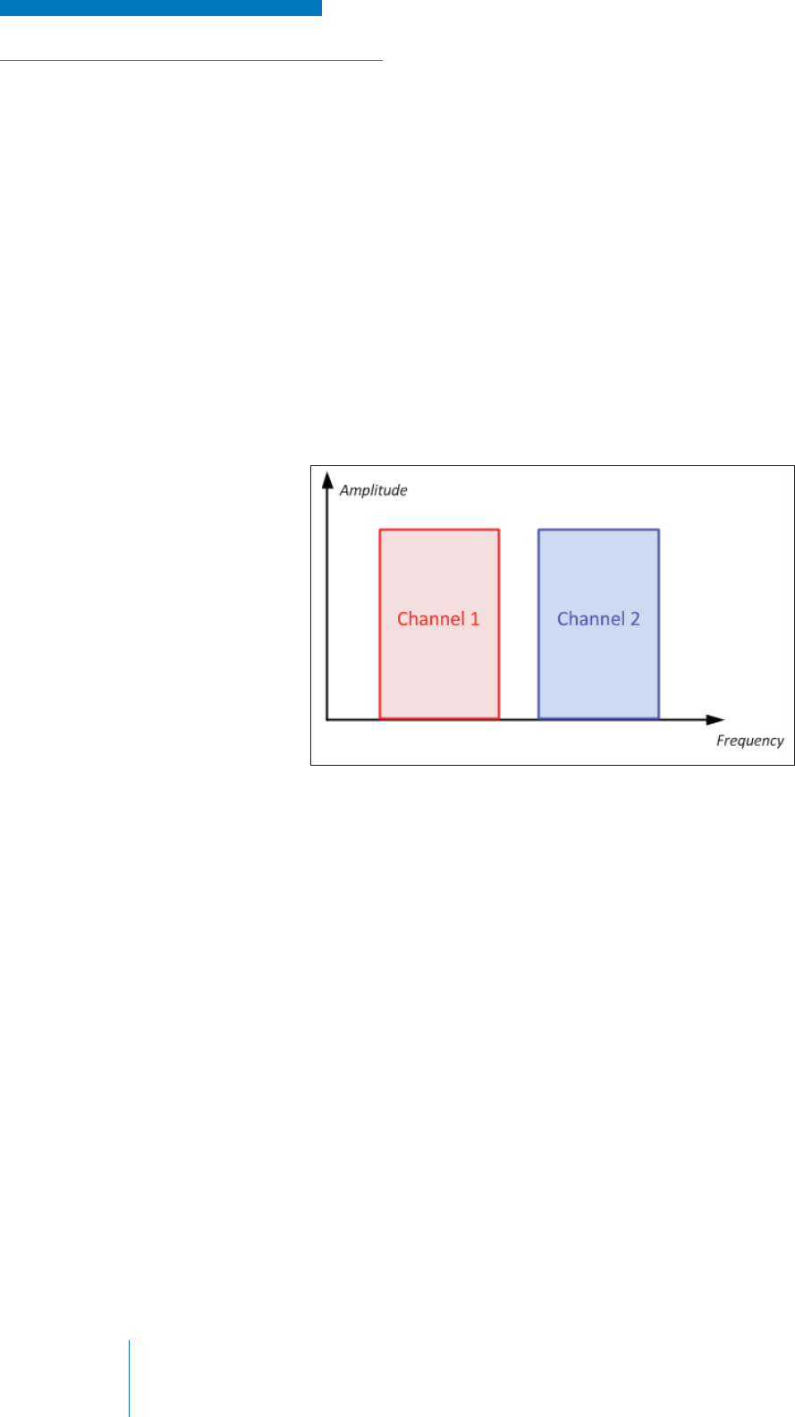
TRAINING GUIDE | RADIO SYSTEM BASICS & RF FUNDAMENTALS
Chapter 3: Radio SystemsPage 56
MULTIPLE USERS AND CHANNEL ACCESS TECHNOLOGIES
Adding more radio equipment and more users to a radio system naturally increases its complexity,
so when planning a radio system beyond the simple single-RX-single-TX arrangement, methods for
managing system usage must be employed.
Frequency Division Multiple Access
Frequency Division Multiple Access (FDMA) is the most fundamental concept in radio
communications when dealing with multiple users in a system. The frequency allocation is divided
into channels, which are then assigned to particular users or for particular functions. The fi gure below
(see Figure 3-8) shows how a frequency band can be divided into two communication channels using
frequency division multiplexing (FDM).
Figure 3-8: FDMA Concept
When a device is communicating on a FDM system using a frequency carrier signal, its carrier
channel is completely occupied by the transmission of the device. For some FDM systems, after
it has stopped transmitting, other transceivers may be assigned to that carrier channel frequency.
When this process of assigning channels is organized, it is called frequency division multiple access.
Transceivers in an FDM system typically have the ability to tune to several different carrier channel
frequencies.
FDMA is a clean concept and can be the only organization scheme required for multiple users
when establishing a system in an area that has a small amount of users. However, in areas where
frequency allocations are not easily available and/or the number of users is high (in densely populate
areas, for example), the usage of available frequencies must be optimized.
Two fundamental solutions to this problem exist:
1. Narrowbanding: Decrease the bandwidth that radio equipment requires to operate, thus
allowing for smaller channels.
2. Channel Access / Sharing Technologies: Apply techniques and add technology to radio
equipment that allows multiple users to access the same channels without interfering with
one another.
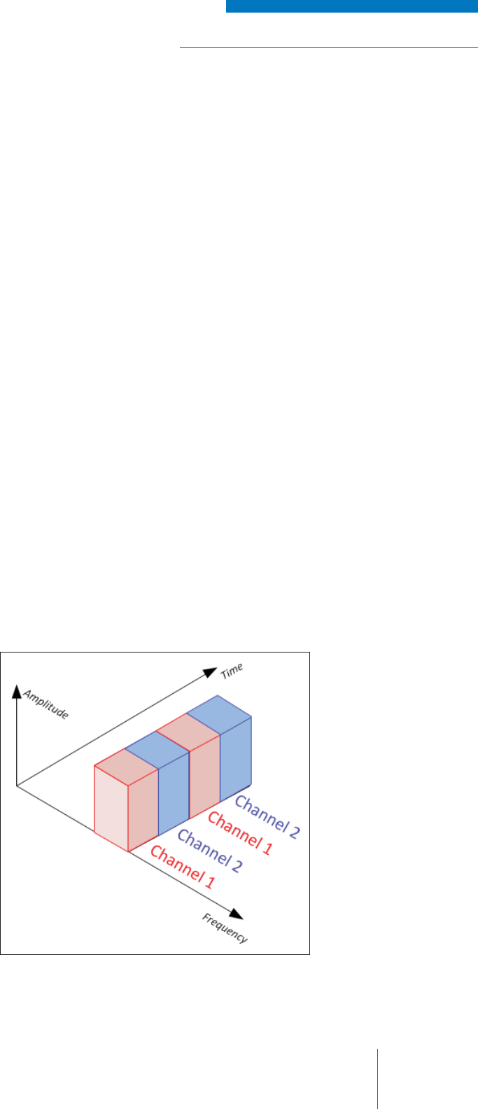
RADIO SYSTEM BASICS & RF FUNDAMENTALS | TRAINING GUIDE
Chapter 3: Radio Systems Page 57
Selective Calling
Selective calling is the simplest type of channel sharing. It allows users to ignore all transmissions on
a channel that not intended for them or their group of users. This is accomplished in analog systems
by adding Continuous Tone Squelch System (CTCSS) subtones—sometimes called PL tones—
to transmissions and having receiving equipment capable of tone squelch operation. Equivalent
processes are found in digital communications, but use various digital codes rather than tones.
A particular CTCSS tone is assigned to a user or group of users; only transmissions on the channel
that contain the assigned CTCSS tone will cause the corresponding user’s radio to un-squelch.
The tone is always present, however, as it is a subtone (not audible and fi ltered out by the radio
equipment). The CTCSS tone can be thought of as a key; only transmitting users that have the
correct key can “open” another user’s receiver.
It should be noted that transmissions that occur at the same time on the channel will still interfere with
each other, even if they are members of different groups and are assigned different CTCSS tones.
As such, selective calling serves more to reduce the nuisance of receiving unwanted transmissions,
rather than providing more effi cient use of a channel.
Time Division Multiple Access
Time Division Multiple Access (TDMA) is a more advanced type of channel sharing that allows users
to share a single radio channel with greater effi ciency. In TDMA, a channel is divided into time slots
that are then allocated to each user; the user can then only use the channel during their designated
time slot.
When a user communicates on a TDMA system, they are assigned a specifi c time position on the
radio channel; this user then can only use the channel within the designated times. By allowing
several users to use different time slots on a single radio channel, TDMA systems increase their
ability to serve multiple users with a limited number of radio channels.
Figure 3-9: Time-Divided Channel
The fi gure below shows how a
single carrier channel is time-
divided into two communication
channels (see Figure 3-9).

TRAINING GUIDE | RADIO SYSTEM BASICS & RF FUNDAMENTALS
Chapter 3: Radio SystemsPage 58
RADIO SYSTEM EQUIPMENT CATEGORIES
When thinking of radio communications on a system level, it is useful to make a further distinction
between the equipment used to directly interface with a user and the equipment that the user does
not directly interface with but is used to support communications:
• Interface equipment
• Radio Infrastructure equipment
• Back-end Infrastructure equipment
Interface Equipment
Interface equipment is any electronic equipment that is interfaced with directly by the user to
communicate into a radio system or directly to another user; this can be a microphone, a computer or
a complete radio in itself.
In the latter case, the sending and receiving interface equipment communicate directly, no additional
infrastructure is needed (e.g., two people speaking on ‘walkie-talkies’).
Radio Infrastructure
Radio infrastructure consists of radio equipment that is used to enhance coverage capabilities
of a radio system to extend coverage, overcome physical obstacles, include a greater number of
users and more. Infrastructure is logically positioned between the sending and receiving interface
equipment.
Infrastructure typically consists of radio stations that serve as interface points into a system and/or
interaction points within a system. Infrastructure can generally be considered to be larger in size and
higher in power than interface radio equipment.
When in use, a radio infrastructure is considered a fi xed and/or permanent point within the radio
communications system; it should be noted, however, that transportable infrastructure is available
that can be moved and deployed as necessary to establish a radio communications system where
one does not permanently exist.
When speaking of LMR systems, radio infrastructure is further divided into two categories:
1. Conventional: Communication management (e.g., call routing, channel allocation, channel
selection) is a manual / user-determined process.
2. Trunked: Communication management is an automated process.
Backhaul Infrastructure
Some more complex radio communications systems employ Backhaul infrastructure to interconnect
radio equipment using a different form of electronic communications technology such as telephony or
IP (internet) connections.
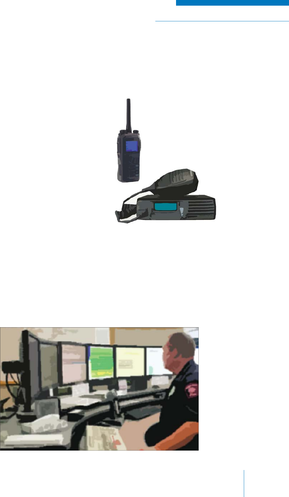
RADIO SYSTEM BASICS & RF FUNDAMENTALS | TRAINING GUIDE
Chapter 3: Radio Systems Page 59
INTERFACE EQUIPMENT
Radio interface equipment takes many forms, from pagers to mobile phones to commercial radio
equipment. For the sake of this text, we will focus on the most common types used in LMR.
Portables
Portable Handsets (or simply ‘Portables’,
or sometimes ‘Subscribers’ depending on
network confi guration) are small handheld
radio transceivers that can communicate into
infrastructure or directly to other portables. They
are generally ruggedized for heavy use, are
battery operated and have a relatively low power
transmitting capability (see Figure 3-10).
Mobiles
Mobile units (or ‘Mobiles’) are similar in
operation to handsets, but are usually
mounted inside a vehicle; for this reason
they are generally larger in size and have
higher transmit power capabilities (See
Figure 3-11).
Figure 3-11: Mobile
Figure 3-12: Consoles
Consoles
Consoles are interface points that not only communicate, but also control the operation of
infrastructure equipment and are thus used to manage communications within a system. These range
in form and complexity, from a terminal that looks like a stationary telephone, to a full computer setup
with monitors and headsets. Consoles differ in many respects to mobiles and portables, particularly
in that the latter are used in the fi eld as transportable communications devices and consoles are
generally at a fi xed location (see Figure 3-12).
Figure 3-10: Portable
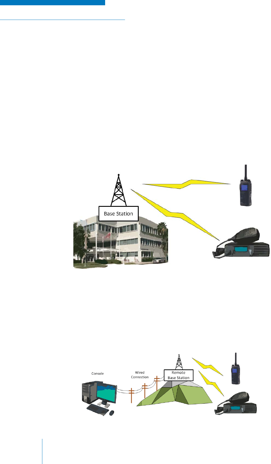
TRAINING GUIDE | RADIO SYSTEM BASICS & RF FUNDAMENTALS
Chapter 3: Radio SystemsPage 60
CONVENTIONAL RADIO INFRASTRUCTURE
Conventional infrastructure describes any geographically fi xed radio system in which the users of
the system directly manage communication traffi c within the system. Fundamentally, this means
allocating channels to users, which are then manually selected by the users when they need
to be used. While there is some limited channel selection and signal routing tools available on
conventional systems, they are relatively basic when compared to the automated functions of Trunked
infrastructure (see the next section). Since conventional systems are relatively simple, they still
comprise the majority of radio systems used today.
Base Stations
A base station is a radio station that serves as an infrastructure access point into a radio
communications system. It can provide a two-way communications point with other infrastructure or
interface equipment, or can provide a one-way broadcast communications to multiple receiving users
(see Figure 3-13).
Figure 3-13: Base Station Setup
Figure 3-14: Remote Base Station Setup
Base stations typically operate in simplex mode, either transmitting or receiving, but not both
simultaneously.
The base station is connected to the interface equipment and will allow the user to communicate via
the infrastructure network to other users. The interface equipment is often collocated with the base
station (a handheld microphone connected right to the radio, for example), however, this is not always
the case. Sometimes it is more convenient to have the large, high-power equipment located remotely,
which is known as a remote base station confi guration (see Figure 3-14).

RADIO SYSTEM BASICS & RF FUNDAMENTALS | TRAINING GUIDE
Chapter 3: Radio Systems Page 61
In this remote base station confi guration, one of the following technologies must be used to connect
the user’s interface equipment to the base station infrastructure equipment.
E&M
E&M (which stands for either Ear and Mouth, or Earth and Magnet)) is the fi rst and most basic form
of remote control for a base station. E&M provides a set of protocols for using a two-wire / telephone
connection (an “E” lead and an “M” lead) to send audio signals and a Push-To-Talk (PTT) signal that
tells the transmitter to start transmitting the input audio signal. Alternately, E&M protocols can also
use a microwave link, which is another separate RF channel that uses a different set of technologies
and frequencies.
There are fi ve different E&M interface types or models named Type I, II, III, IV, and V. Each type has
a different wiring arrangement, hence a different approach to transmit E&M supervision signaling (on-
hook / off-hook signaling). The signaling side sends its on-hook/off-hook signal over the E-lead. The
trunking side sends the on-hook / off-hook over the M-lead.
Tone Remote
A tone remote base station also employs a wired or microwave link, but rather than just simple audio
and PTT functions used in E&M, a tone remote has more advanced capability. A remote console may
be located in the same building as the transmitter, or they may be separated by many miles and use
telephone lines or microwave links to connect the transmitter with the tone remote console.
Control signals and voice are sent from the tone remote console, over the dedicated pathway, to
the transmitter. It is necessary to install a tone remote adapter to the transmitter to convert the
tone remote signals to actual channel and Push-to-Talk (PTT) functions. Standard Tone Remote
Frequencies are shown in Table 10.
Table 10: Standard Tone Remote Frequencies and Levels
Standard Tone Remote Frequencies Relative Levels Tone Duration
High Level 2175 Hz Guard Tone 10 dBm 120 ms
1950 Hz Transmit F1 Function 0 dBm 40 ms
1850 Hz Transmit F2 Function 0 dBm 40 ms
2050 Hz CTCSS Monitor Function 0 dBm 40 ms
Low Level Guard Tone -20 dBm 20 ms
Voice Peaks 0 to 5 dBm
Figure 3-15 shows a Tone Remote Control sequence the host will send to control the base station.
Figure 3-15: Tone Remote Control Sequence
HIGH LEVEL
GUARD TONE
(HLGT)
FUNCTION
TONE LOW LEVEL GUARD TONE (LLGT)
AUDIO
120 ms 40 ms Length of Transmit
-30 to +10 dBm
-10 dB from HLGT
-30 dB from HLGT
-6 to -18 dB from HLGT

TRAINING GUIDE | RADIO SYSTEM BASICS & RF FUNDAMENTALS
Chapter 3: Radio SystemsPage 62
Note that there may be multiple tones used at a time, for example, if one wishes that a radio function
be performed while the transmitter is transmitting (that is, PTT is enabled by a tone). There are two
different ways this case is handled, depending on the manufacturer of the tone remote equipment:
1. Single Tone Format: Function Tones are sent as a separate item from the PTT signal. A
Function Tone is sent at 0 dBm for 350 msec. While a PTT signal is sent at -10 dBm for the
entire time the voice is being transmitted.
2. Sequential Tone Format: In this method, a guard tone of 2175 is sent at +10 dBm for
40 msec, followed by a function tone at 0dbm for 40 msec, which is then followed by a
continuous PTT tone of 2175 at -20 for the entire duration of the voice transmission.
IP Control
The fast growth of internet communications has allowed for rapid expansion of IP controlled remote
base stations; this is often called Radio-Over-IP (RoIP). This solution requires the infrastructure
equipment to be fi tted with a device that connects via an IP network connection such as Ethernet, to a
console interface with the required control software.
This method of remote base station control not only circumvents the high costs of leasing telephone
lines, but also allows for expanded features and functionality, such as monitoring levels, alarming,
logging communications, integration with other technologies such as cellular communications and
others. While the disadvantages are few, network security and reliability must be seriously considered
in these applications.
Repeaters
A repeater is as an intermediate radio station that re-transmits the signal it receives (see Figure 3-16).
Repeaters are used when simple transmitter-to-receiver communications are not possible, for
example:
• When the transmitter is too limited in transmitting power to reach the intended receiver(s)
• When too great a distance separates the transmitter and receiver(s)
• If a permanent obstacle between the transmitter and receiver prevents a path for
communication
• If the frequencies used by the transmitter do not match or are not permitted in the area of
where the receivers are located
Repeaters typically operate in duplex mode, as the instantly relay whatever is being received.
Note that repeaters can be confi gured to connect to other repeaters creating a network that can span
a potentially large distance and overcome various physical obstructions.
Figure 3-16: Repeater Setup
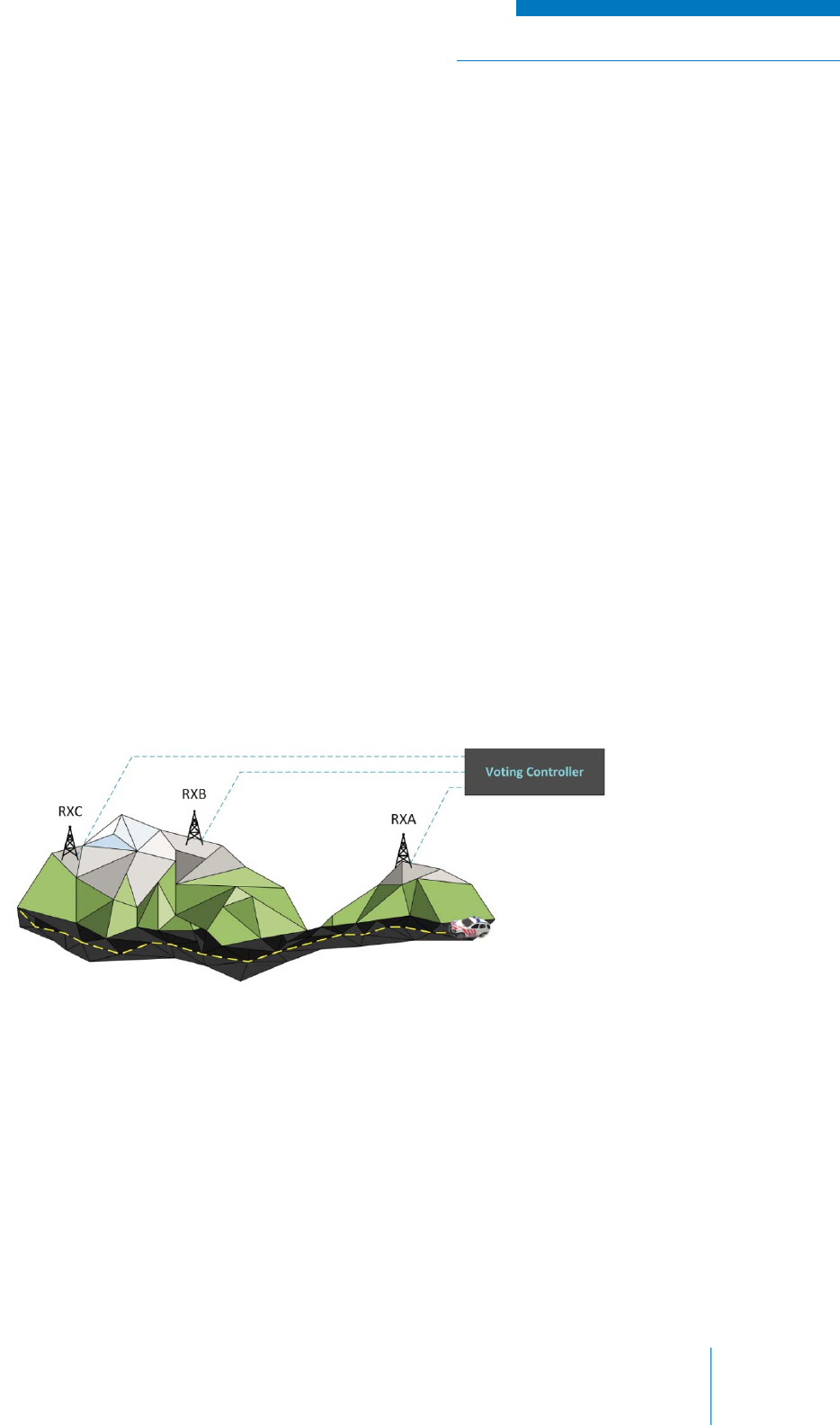
RADIO SYSTEM BASICS & RF FUNDAMENTALS | TRAINING GUIDE
Chapter 3: Radio Systems Page 63
Voting
Voting is a more advanced confi guration that is used to overcome challenges of reception coverage in
radio system infrastructure.
Voting involves using multiple receiver stations to maintain optimal reception from portable / mobile
users that are transmitting from various locations in a given area. As a portable / mobile user moves
in the area, their line of sight to the infrastructure receiver can become blocked by terrain such as
mountains or buildings. When his happens, any transmissions the user may try to send from their
mobile / portable may not reach the receiver, or if they do, the signal may be noisy. This is a particular
problem when the coverage area is large and geographically diverse.
A voting confi guration solves this problem by having receiver stations deployed at various locations
over the area so that there is reception coverage everywhere that it may be needed. These receivers
all have a backhaul (i.e., IP, wire or radio) connection to a central device known as a voting controller.
When a transmission from the user occurs, the voting controller ‘listens’ to the demodulated audio
from each of receivers in the system and determines which one has the strongest signal. It does
this by measuring the amount of noise in the audio using statistical methods to calculate a signal’s
Signal -to-Noise ratio (S/N) or alternately the Received Signal Strength Index (RSSI) for analog
communications, or Bit Error Rate (BER) for digital communications.
Once the voting controller picks (i.e., votes for) the best received signal, it passes this signal onto the
intended location via a backhaul connection or radio re-transmission.
To better understand the concept of voting, imagine the following scenario involving a car equipped
with a mobile radio traveling down a highway surrounded by mountains (see Figure 3-17).
Figure 3-17: Example – No Voting Process
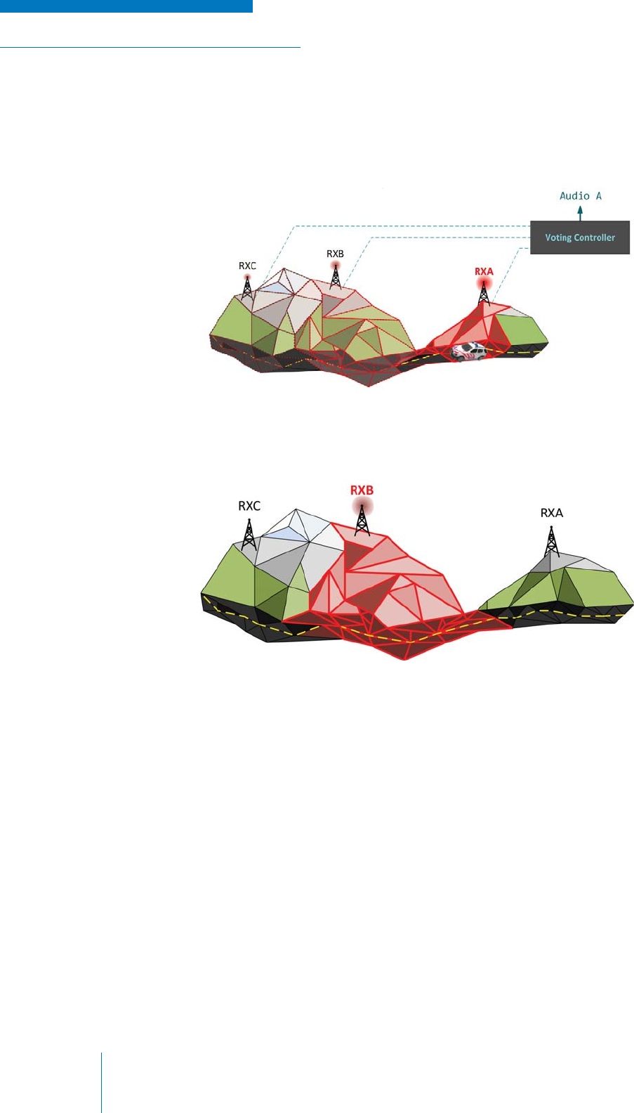
TRAINING GUIDE | RADIO SYSTEM BASICS & RF FUNDAMENTALS
Chapter 3: Radio SystemsPage 64
When the driver of the car is driving near the beginning of the highway and tries to transmit, the signal
is strongly picked up by the nearby receiver A, more poorly by the distant receiver B and hardly at all
by the obscured receiver C (see Figure 65). In this case, the voting controller chooses to ignore the
audio received by receivers B and C, since the signal from receiver A has the least amount of noise
and is therefore the strongest.
Figure 3-18: Voting Controller – Chooses RXA
Figure 3-19: Voting Controller – Chooses RXB
As the car moves down the highway, the signal at receiver B becomes stronger, thus the voting
controller ignores the audio from receivers A and C (see Figure 66).
When the receiver is not receiving any intelligible signal, it produces a continuous Status Tone over
the backhaul line to the controller; this allows the controller to exclude receivers that are not receiving
a signal at all from the voting process.
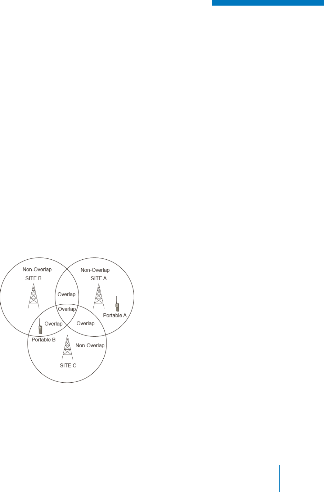
RADIO SYSTEM BASICS & RF FUNDAMENTALS | TRAINING GUIDE
Chapter 3: Radio Systems Page 65
Simulcast
Simulcast is a more advanced confi guration that is used to overcome challenges of transmission
coverage in radio system infrastructure while improving frequency effi ciency (see Figure 3-20).
Simulcast systems use multiple transmitter stations using the same transmitting frequency to provide
a more complete range of coverage rather than a single centrally located transmitter (Broadcast)
or multiple transmitters using multiple frequencies (known as Multicast). Like in a voting system,
the communication is managed by central control equipment that routes the audio signals to the
transmitter sites via backhaul connections.
In theory, all of the stations transmit or re-transmit the same signal on the same frequency
simultaneously. Since the transmitting frequency is the same at each station, a single channel can
be used to receive the signal, regardless of which coverage area the mobile / handheld receiver
fi nds itself in—meaning that the user does not have to change channels and frequency allocation
requirements are kept to a minimum.
While this seems like a simple concept, the technical challenges involved in a Simulcast system can
be great, because when the same signal is transmitted from multiple points there will likely be areas
of overlap where a signal from multiple transmitters will be received at once.
Recall that two signals received at a single point will add together; if they are in-phase the addition
will make the signal stronger, if they are out-of-phase, the signal will be diminished or distorted. Since
the transmitters vary in distance to a receiver fi nding itself in this overlap area, the signals will arrive
at different times causing destructive interference. If one signal is much stronger than the others, this
isn’t much of a problem because the receiver can inherently discern the stronger signal (known as
capture effect), however if one or more signals are similar in strength this is a signifi cant problem.
Figure 3-20: Site Transmission Coverage
Additionally, if the frequencies of all of the
stations are not exactly the same (or as close
as possible), other detrimental interference can
occur in overlap areas.
Given these technical challenges, there are a
number of solutions that must be employed in a
Simulcast system for communications to work
correctly:
• Site placement and design
• Audio phase delay and amplitude
equalization
• RF frequency stabilization
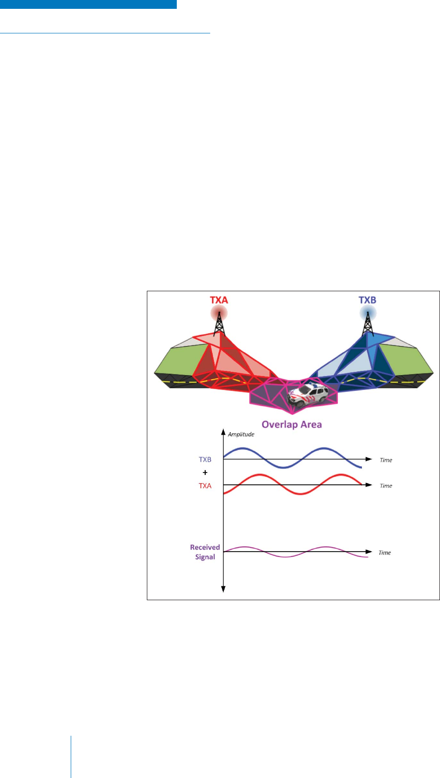
TRAINING GUIDE | RADIO SYSTEM BASICS & RF FUNDAMENTALS
Chapter 3: Radio SystemsPage 66
Site Placement and Transmitter Characteristics
The easiest way to avoid the problems that arise when areas of transmission overlap is to design
the radio system such that coverage is maximized and overlap is minimized. Naturally this optimized
scenario is diffi cult to achieve in practice, however transmitter placement and height can be varied to
provide the best solution possible. Varying the output power of the transmitters can also provide some
control over overlap areas, but this approach is constrained by equipment and regulatory limitations
on power and its effectiveness is a point of contention among experts.
Audio Phase Delay and Time Synchronization
Introducing a calculated time delay into the transmissions can ensure that interference is not
destructive at points of interest / heavy use that fall into areas of overlap.
As an example, imagine a mobile receiver in a car needs to receive a signal on a highway that falls
in the overlap area of two transmitters (see Figure 3-21). The signal from the nearest transmitter
reaches the mobile fi rst, so when the signal from the further transmitter reaches the mobile, it
becomes a source of interference.
Figure 3-21: Example – Transmission Interference
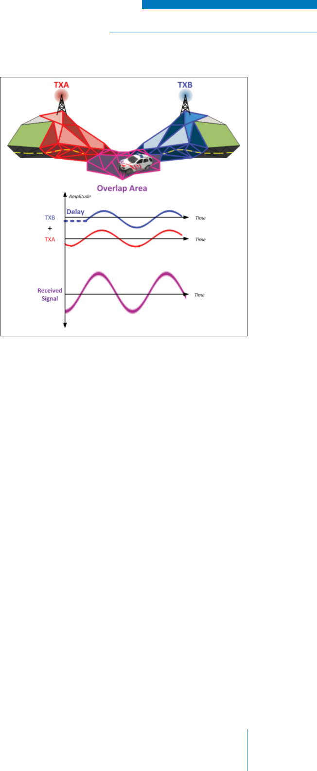
RADIO SYSTEM BASICS & RF FUNDAMENTALS | TRAINING GUIDE
Chapter 3: Radio Systems Page 67
To correct this, the time it takes the signal
from the furthest transmitter is calculated
and the signal from the nearest transmitter
is delayed accordingly so that both signals
arrive approximately at the same time
(see Figure 3-22).
Since the phase of the signals is the
same, they will add together in such a
way that is not destructive because the
audio that is captured by the receiver is
the same regardless of which signal is
received.
This solution, however, introduces a new
problem in that the transmitter stations
need to be very carefully synchronized
in time so that one transmitter may
be delayed relative to another. This
is achieved by the addition of precise
timing equipment to each transmitter
station. Often, this is a GPS receiver that
receives a very high-accuracy timing
signal produced and transmitted by
Geosynchronous Positioning System
(GPS) satellites that orbit the Earth.
Figure 3-22: Example – Audio Phase Delay
Note that the process of adding delay often requires expensive equipment and substantial
engineering, such as fi eld testing or computerized delay spread calculations, to gauge exactly how
long it takes for a transmission from a particular station to reach a given point.
Interference can further be controlled by varying the amplitude of the input audio signal on each of
the transmitting stations; in doing this, the received signal is uniform regardless of which station it is
received from.
RF Frequency Stabilization
When multiple signals are apparent in the overlap area, destructive interference between RF signals
will occur when the signals do not match in frequency due to phase misalignment. The result is an
audible “buzz” that can affect the quality of received audio from simply being annoying to the point of
incoherence.
This is mitigated by using transmitter equipment that has a very high frequency stability specifi cation,
or by adding equipment that eternally controls or disciplines the transmitter oscillator to produce
a very stable frequency. Once again, a GPS receiver is used to discipline the oscillators in the
transmitter equipment to a high-accuracy reference signal.
When to Use Simulcast
Simulcast is often used in conjunction with voting infrastructure technology to provide a full
transmission and reception solution. Due to the challenges inherent in Simulcast systems,
engineering and equipment costs tend to be considerably higher than in simpler confi gurations. The
use of a Simulcast confi guration should therefore only be planned when other, simpler confi gurations
are not possible.

TRAINING GUIDE | RADIO SYSTEM BASICS & RF FUNDAMENTALS
Chapter 3: Radio SystemsPage 68
TRUNKED RADIO INFRASTRUCTURE
Trunked radio infrastructure is a more advanced geographically fi xed radio system infrastructure
that uses computer systems to automate the management of communication traffi c within the radio
system. While this approach is generally more expensive due to the need for advanced control
equipment and increased engineering / commissioning complexity, there are signifi cant advantages to
the use of a trunked system over a conventional system:
• Provides a signifi cant improvement in ease of use over conventional radio infrastructure since
users don’t have to manually select channels
• Allows for a large number of users to use limited frequency resources with greater effi ciency
due to the power of computerized channel management
• Enables advanced communication management by allowing communication to specifi c
individual users or combinations/groups of users
Trunking Operation (Dedicated Control Channel)
In a trunked radio system application, mobiles and portables are called subscribers, since they are
registered within the radio system and managed by the system controller. Subscribers are assigned
to talkgroups (or simply groups) and each group has a number of channels that are shared among
the subscribers. These user communication channels are called traffi c channels (see Figure 3-23).
Figure 3-23: Trunked Radio System with Multiple Traffi c Channels

RADIO SYSTEM BASICS & RF FUNDAMENTALS | TRAINING GUIDE
Chapter 3: Radio Systems Page 69
There is also a specifi c channel known as the control channel, which is used by the system controller
equipment to wirelessly send information and grant channel usage permission to the user’s mobiles
or portables. The information on the control channel operates in the background and is not audibly
heard by user. The control channel is usually a dedicated channel (i.e., a reserved frequency), but
in some cases where frequency availability is particularly scarce, the control channel switches to an
available traffi c channel. Some trunking technologies forgo having a control channel altogether and
rely on subtones on traffi c channels to perform subscriber control functions.
When a user wishes to make a call to another user or group of users, the user’s subscriber
automatically sends a request to the controller via the control channel. The control channel then
grants the user’s and recipient’s subscribers access to a vacant traffi c channel and a communications
session, known as a call, is established.
All traffi c goes through the controller station; the subscriber transmitter signal is received and then
retransmitted to the designated users and/or groups. Once a subscriber or a group of subscribers
is granted access to a traffi c channel, they have exclusive access to the channel for the duration
of their call. Note that this process is very fast and mostly transparent to the user. From the user’s
perspective, the PTT button on the subscriber is depressed and the call is simply initiated with little
noticeable delay.
Trunking Confi gurations
As with conventional infrastructure, trunking infrastructure can be arranged into different
confi gurations to deal with the challenges of terrain and frequency availability.
A single-site trunking confi guration is the simplest type of trunking system, in which a centrally located
controller station manages all traffi c and control functions of subscribers within its coverage area.
A multi-site trunking confi guration consist of two or more trunking controller stations with separate
coverage areas, linked together via IP backhaul communications. Voting and/or Simulcast
methodologies are sometimes applied to optimize reception and transmission coverage, respectively,
however this comes at the cost of increased system complexity.
Trunking Format
While analog trunking was traditionally available, the functional requirements of trunked systems are
more easily addressed in a digital radio system. Development of new standards and technologies,
as well as reduction in cost of the latter, has meant that the majority of trunked system that are now
implemented use digital radio.

TRAINING GUIDE | RADIO SYSTEM BASICS & RF FUNDAMENTALS
Chapter 3: Radio SystemsPage 70
DIGITAL RADIO
A person or organization wishing to establish a radio system using any of the conventional or trunked
applications described above can do so using either analog radio equipment, digital radio equipment
or a mixture of both. While it is tempting to use the latest and most advanced equipment, it is
important to understand the strengths and weaknesses of both types of technology, thus allowing one
to make an informed choice.
The Advantages of Digital Radio
The process of digitizing audio prior to transmitting it allows for some signifi cant advantages over
analog communications:
• Reduction of Noise: The process of digitizing an analog signal inherently removes noise
from a signal that is to be transmitted. On the side of reception, error correction can be
performed to restore bits that were “lost” in the transmission by way of statistical calculation.
• Improved Bandwidth: The sending of bits rather than complex analog signals can reduce
the bandwidth required for effective communication.
• Improved Security: Analog signals can theoretically be received by anyone who knows
which frequency to “listen” to. Digital signals, however, can be very effectively encrypted (or
encoded), meaning that only a recipient who has the correct encryption key can listen to and
understand the transmission; anyone else trying to listen in would only hear unintelligible
noise.
• Advanced Functionality: In addition to sending the bits of digitized audio in a transmission,
other digital information can be sent that provide useful information such as user identity,
diagnostics and control functions.
The Disadvantages of Digital Radio
While digital radio affords some advantages, there are still a number of reasons why analog
communications remain widely used:
• Decreased Coverage: Analog radios can receive relatively weak signals; though the
audio that the user hears is noisy, it is often intelligible. Digital radio on the other hand
requires received bits to produce intelligible sound; if too many bits are corrupted during
the transmission, the processing equipment will simply not output any audio at all. As a
result, areas where intelligible analog audio can be received are abruptly cut off in digital
communications. Not only does this mean a decreased coverage area, but also means
unnerving effects for users that do not have any audible indication that a signal is fading.
• Audio Delay: The conversion to and from analog signals and the processing required
introduces a delay that some users may fi nd annoying or inconvenient.
• Higher Equipment Cost: Although the cost of digital equipment has reduced in recent years,
the technology is still more expensive than traditional analog radio.
• Adherence to Various Standards: Analog radio is a fundamental technology that can
generally be accessed by equipment produced by any manufacturer. Digital radio, however,
introduces an element of computing which requires operational protocols. While there are
several standardized protocols (P25 Digital, TETRA or DMR, for example), a manufacturer’s
equipment will generally adhere to only one of them, meaning it will not work with another
manufacturer’s equipment that uses a different standard.

TRAINING GUIDE | RADIO SYSTEM BASICS & RF FUNDAMENTALS
Chapter 3: Radio SystemsPage 71
This Page Intentionally Left Blank

TRAINING GUIDE | RADIO SYSTEM BASICS & RF FUNDAMENTALS
Chapter 3: Radio SystemsPage 72
This Page Intentionally Left Blank
Codan Radio Communications
43 Erie Street, Victoria, BC
Canada, V8V 1P8
www.codanradio.com
LMRsales@codanradio.com
Toll Free Canada and USA
Phone: 1-800-664-4066
Fax: 1-877-750-0004
International
Phone: 250-382-8268
Fax: 250-382-6139
©2016 Codan Limited All Rights Reserved.
TG-003-1-0-0
www.codanradio.com
