306.0D Bohn Evaporator Coils
2014-11-10
: Coffee Bohn Evaporator Coils Bohn Evaporator Coils images
Open the PDF directly: View PDF ![]() .
.
Page Count: 20
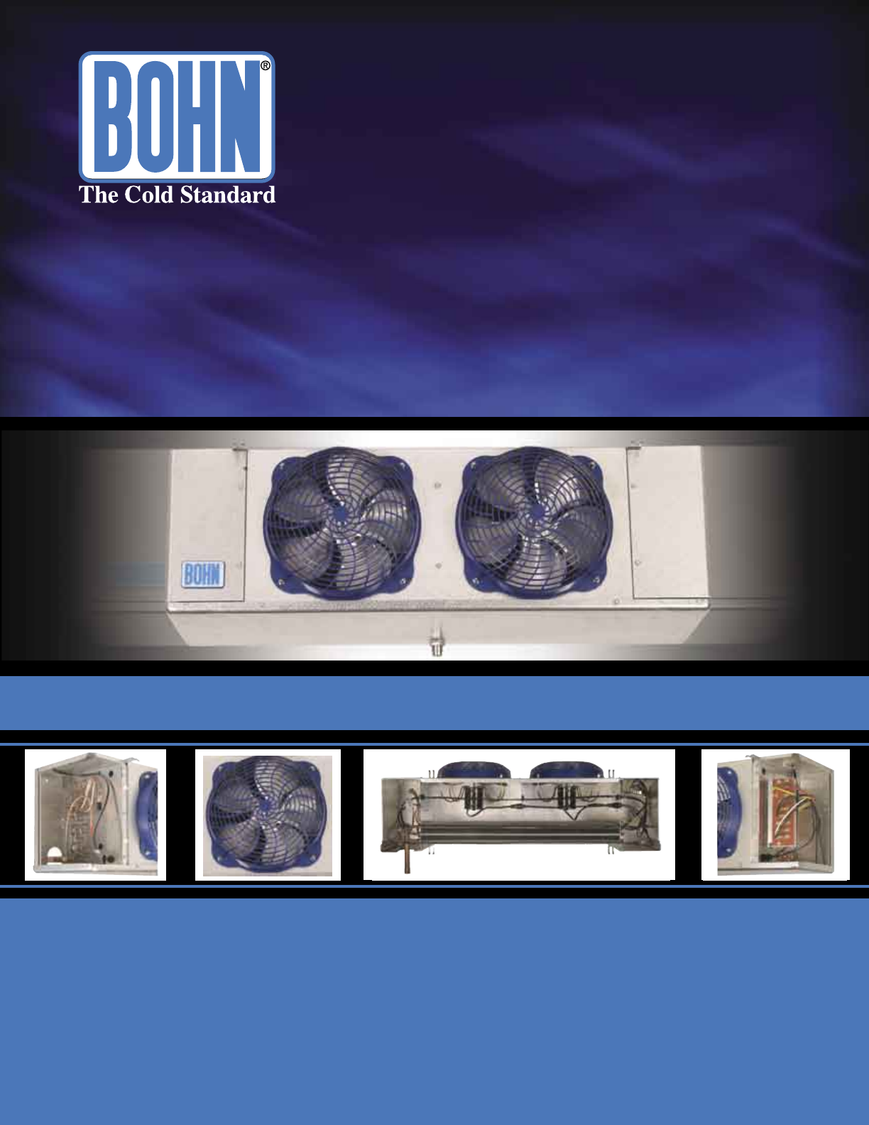
Low Profile Unit Coolers
Model ADT - Air Defrost • Model LET/LLE - Electric Defrost • Model HGT - Hot Gas Defrost
Bulletin 306.0D
August 2004
(Replaces 306.0C • 3/04)
- 2 -
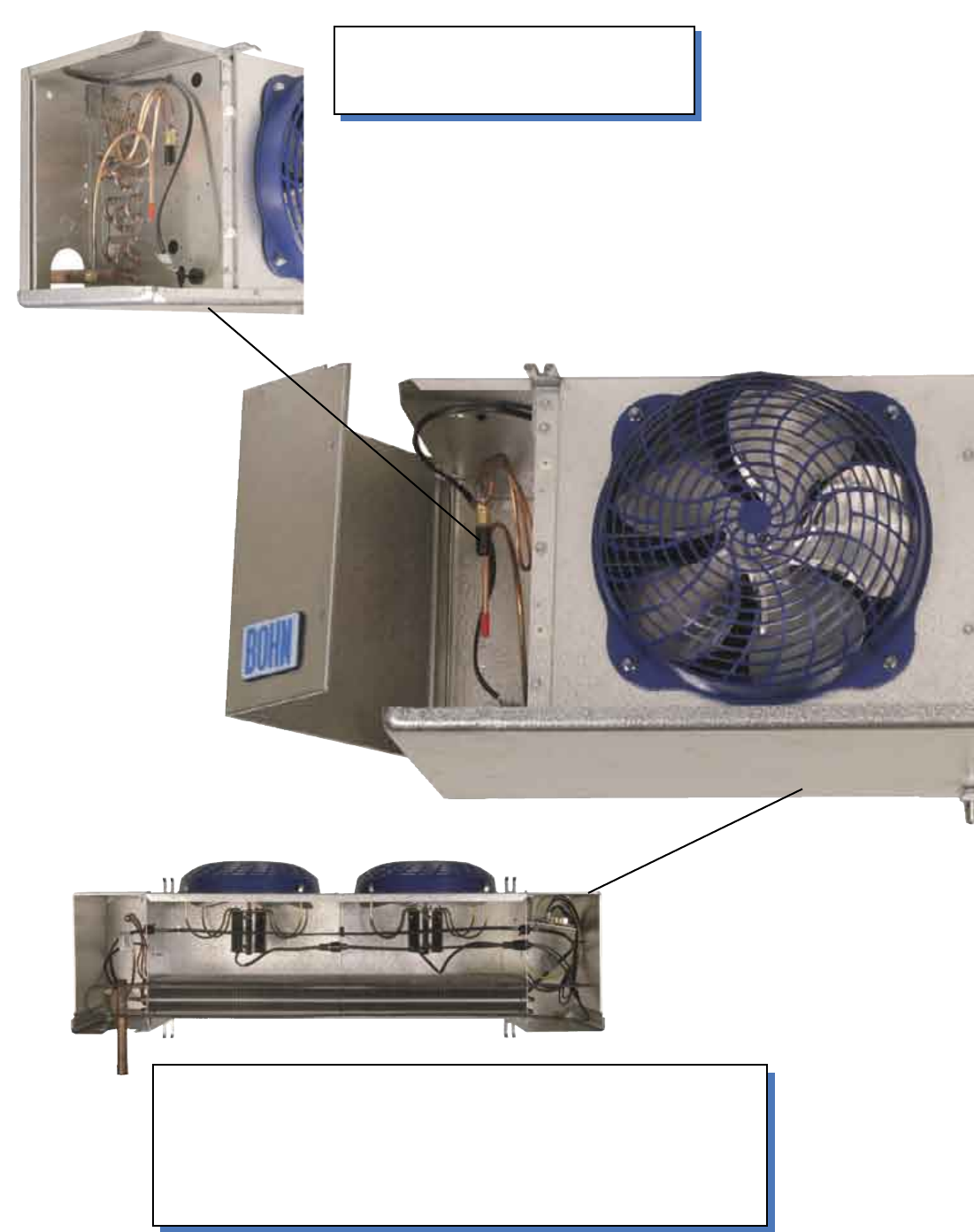
Motor harness and solenoid harness are easier to access from
the bottom of the coil. The drain pan heater is located on
the bottom of the coil, which allows the drain pan to be
removed without the removal of the heater. The drain pan
heater also extends into the end panels for more heat in the
side panel cavities.
view from bottom
Front access to refrigeration
components. Hanger bars are now
located on the inside of the cabinet
- 3 -
Improved drain pan design. Drain pan hole
is now located to the back of the drain pan
and is larger in diameter 3/4” ID (3/4” MPT
drain line fitting).
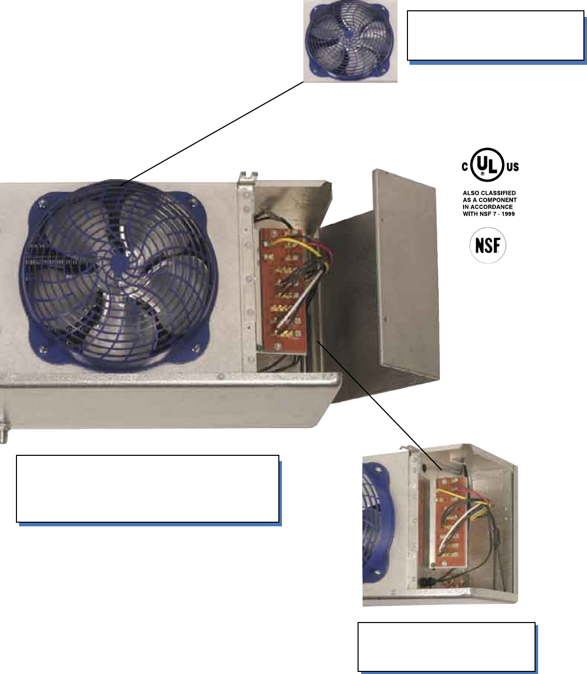
Front facing electric board for
easy access. Optimized space
in end panels.
Improved plastic blue guard
design (wire guard available
as an option).
- 4 -
Cabinet:
• Extended model and capacity offerings to better match with Bohn condensing units.
• New cabinet design features easy front access to electrical and refrigeration components.
• Smaller physical cabinet size with optimized interior space.
• Panels are isolated for quiet operation.
• Schrader valve on suction header
• Hanger bars are located inside the cabinet.
• On 4-6 fan models, lanyards are included as a drain pan holder.
• The electrical board is front-facing for easy access.
• Liquid line solenoid wire harness factory-installed for quick installation
• Pre-drilled holes on the back of the unit for room thermostat and controls.
Heaters and Coil:
• Internally enhanced tubing and fin design for higher efficiency.
• Coil heater slots have been enlarged.
• Reduced heater wattages.
• Hot gas loop on bottom of coil for easier access.
• Fixed defrost termination for electric, adjustable defrost termination for hot gas.
Guards and Motors:
• Improved blue plastic guard design.
• Motor harness and solenoid harness are at the bottom of the unit for
easy access.
• Motor harness easily plugs in.
Drain Pan:
• Improved drain pan design.
• Drain hole is located to the back of the unit with larger diameter, 3/4”
ID (3/4” MPT).
• Drain pan heater is located at the bottom of the coil for easier access.
• Extended drain pan heaters for more heat in the end compartments.
• Drain pan heater design allows for more contact with coil and drain pan.
Options:
• Totally enclosed PSC 115/1/60, PSC 208-230/1/60 or PSC 460/1/60 motors.
• 460/1/60 PSC motors.
• Beacon II™ compatible, board mounts inside the refrigeration access panel.
• Unit configurations: mounted components, pre-charged or quick connect fittings
• Room thermostat option mounted on the back of the unit or in the front cavity of the unit (with
front access to adjust thermostat)
• Glycol circuiting available on most models
• Copper fin copper tube coils
• Coil and fin coatings available
MODEL NOMENCLATURE
ADT 120 A K
Model Series:
ADT = Air defrost
LET = Electric defrost, 6 FPI
LLE = Electric defrost, 4 FPI
HGT = Hot gas defrost
Size X 100 = BTUH
Design Revision:
Electrical Code:
A = 115/1/60
B = 208-230/1/60
C = 208-230/3/60
M = 460/1/60
Features&Benefits
Features & Benefits
- 5 -
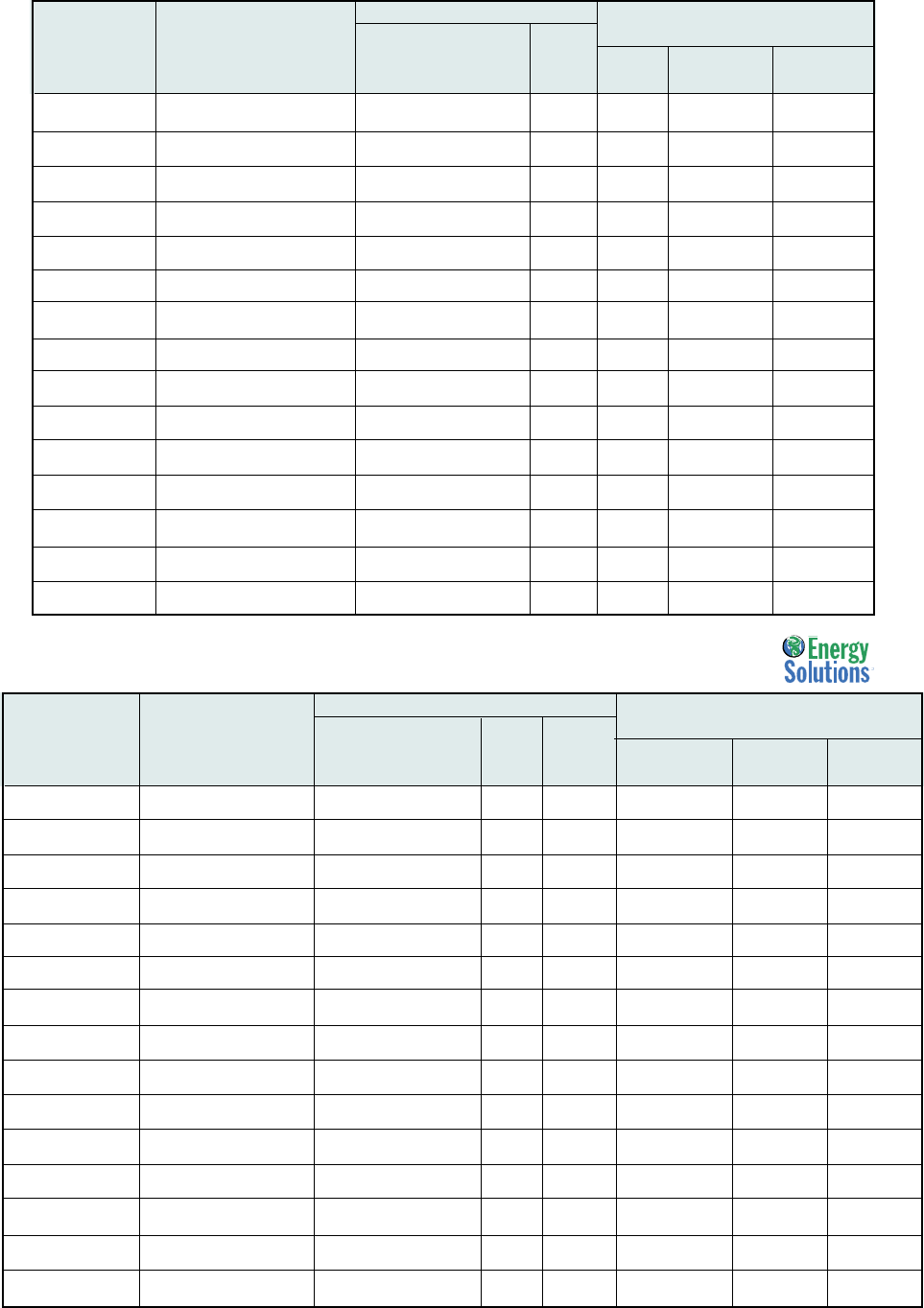
Capacities
Air Defrost Capacities
ADT Air Defrost Models 60 Hz. with PSC Motors
ADT Air Defrost Models 60 Hz. with Shaded Pole Motors
Capacity Fan Data Shaded Pole Motor Data
BTUH / Watts (Total Amps/Watts)
ADT 10°F TD/ 6°C TD 115/ 208-230/
Model Size +25°F SST/-4°C SST CFM / m3H No. HP 1/60/Watts 1/60/Watts
ADT 040 4,000 730 1 1/15 1.8 1.0
1,170 1,240 116 122
ADT 052 5,200 700 1 1/15 1.8 1.0
1,520 1,189 116 122
ADT 065 6,500 650 1 1/15 1.8 1.0
1,900 1,104 116 122
ADT 070 7,000 1,460 2 1/15 3.6 2.0
2,050 2,481 232 244
ADT 090 9,000 1,400 2 1/15 3.6 2.0
2,640 2,379 232 244
ADT 104 10,400 1,400 2 1/15 3.6 2.0
3,050 2,379 232 244
ADT 120 12,000 1,300 2 1/15 3.6 2.0
3,500 2,209 232 244
ADT 130 13,000 1,300 2 1/15 3.6 2.0
3,810 2,209 232 244
ADT 140 14,000 2,100 3 1/15 5.4 3.0
4,100 3,568 348 366
ADT 156 15,600 2,100 3 1/15 5.4 3.0
4,570 3,568 348 366
ADT 180 18,000 1,950 3 1/15 5.4 3.0
5,270 3,313 348 366
ADT 208 20,800 2,800 4 1/15 7.2 4.0
6,100 4,758 464 488
ADT 260 26,000 3,250 5 1/15 9.0 5.0
7,620 5,522 580 610
ADT 312 31,200 3,900 6 1/15 10.8 6.0
9,140 6,627 696 732
ADT 370 37,000 3,900 6 1/15 10.8 6.0
10,840 6,627 696 732
Capacity Fan Data PSC, PSC-TE Motor Data
BTUH / Watts (Total Amps/Watts)
ADT 10°F TD/ 6°C TD 115/ 208-230/ 460/
Model Size +25°F SST/-4°C SST CFM / m3H No. HP 1/60Watts 1/60 Watts 1/60Watts
ADT 040 4,000 730 1 1/15 1.0 0.5 0.4
1,170 1,240 82 91 117
ADT 052 5,200 700 1 1/15 1.0 0.5 0.4
1,520 1,189 82 91 117
ADT 065 6,500 650 1 1/15 1.0 0.5 0.4
1,900 1,104 82 91 117
ADT 070 7,000 1,460 2 1/15 2.0 1.0 0.8
2,050 2,481 164 182 234
ADT 090 9,000 1,400 2 1/15 2.0 1.0 0.8
2,640 2,379 164 182 234
ADT 104 10,400 1,400 2 1/15 2.0 1.0 0.8
3,050 2,379 164 182 234
ADT 120 12,000 1,300 2 1/15 2.0 1.0 0.8
3,500 2,209 164 182 234
ADT 130 13,000 1,300 2 1/15 2.0 1.0 0.8
3,810 2,209 164 182 234
ADT 140 14,000 2,100 3 1/15 3.0 1.5 1.2
4,100 3,568 246 273 351
ADT 156 15,600 2,100 3 1/15 3.0 1.5 1.2
4,570 3,568 246 273 351
ADT 180 18,000 1,950 3 1/15 3.0 1.5 1.2
5,270 3,313 246 273 351
ADT 208 20,800 2,800 4 1/15 4.0 2.0 1.6
6,100 4,758 328 364 468
ADT 260 26,000 3,250 5 1/15 5.0 2.5 2.0
7,620 5,522 410 455 585
ADT 312 31,200 3,900 6 1/15 6.0 3.0 2.4
9,140 6,627 492 546 702
ADT 370 37,000 3,900 6 1/15 6.0 3.0 2.4
10,840 6,627 492 546 702
- 6 -
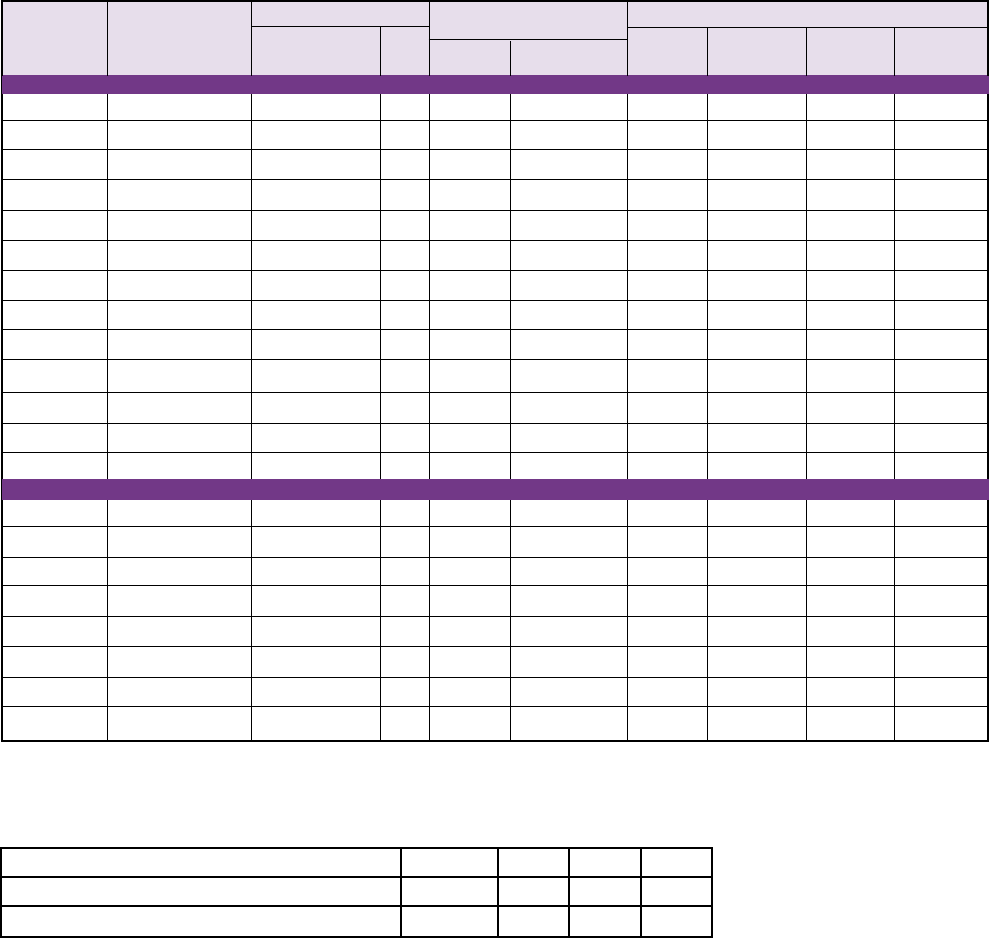
Capacity Correction Factors For Electric and Hot Gas Defrost Units
Saturated Suction Temperature °F +20 -10 -20 -30
Saturated Suction Temperature °C -7 -23 -29 -34
Multiply Capacity By 1.15 1.04 1.00 0.90
LET/LLE Electric Defrost Models 60 Hz. with Shaded Pole Motors
Capacity Fan Data Shaded Pole Motor Data Defrost Heaters (Total Amps)
BTUH / Watts (Total Amps/Watts)
LET/LLE
10°F /6°C TD
208-230/ 230/ 230/ 460/
Model Size -20°F / -29°C SST CFM / m3H No. HP 1/60 Watts Watts 1/60 3/60 1/60
6 FPI Models
LET 035 3,500 700 1 1/15 1.0 900 3.9 2.3 2.0
1,025 1,189 122
LET 040 4,000 700 1 1/15 1.0 900 3.9 2.3 2.0
1,170 1,189 122
LET 047 4,700 650 1 1/15 1.0 900 3.9 2.3 2.0
1,380 1,104 122
LET 065 6,500 1,400 2 1/15 2.0 1800 7.8 4.5 3.9
1,900 2,379 244
LET 075 7,500 1,300 2 1/15 2.0 1800 7.8 4.5 3.9
2,200 2,209 244
LET 090 9,000 1,300 2 1/15 2.0 1800 7.8 4.5 3.9
2,640 2,209 244
LET 120 12,000 2,100 3 1/15 3.0 2700 11.7 6.8 5.9
3,520 3,568 366
LET 140 14,000 1,950 3 1/15 3.0 2700 11.7 6.8 5.9
4,100 3,313 366
LET 160 16,000 2,600 4 1/15 4.0 3600 15.7 9.0 7.8
4,690 4,418 488
LET 180 18,000 2,600 4 1/15 4.0 3600 15.7 9.0 7.8
5,280 4,418 488
LET 200 20,000 3,250 5 1/15 5.0 4500 19.6 11.3 9.8
5,860 5,522 610
LET 240 24,000 3,900 6 1/15 6.0 5400 23.5 13.6 11.7
7,030 6,627 732
LET 280 28,000 3,900 6 1/15 6.0 5400 23.5 13.6 11.7
8,200 6,627 732
4 FPI Models
4 LLE 041 4,100 690 1 1/15 1.0 900 3.9 2.3 2.0
1,200 1,172 122
LLE 068 6,800 1,380 2 1/15 2.0 1800 7.8 4.5 3.9
2,000 2,345 244
LLE 080 8,000 1,380 2 1/15 2.0 1800 7.8 4.5 3.9
2,340 2,345 244
LLE 102 10,200 2,170 3 1/15 3.0 2700 11.7 6.8 5.9
2,990 3,687 366
LLE 136 13,600 2,760 4 1/15 4.0 3600 15.7 9.0 7.8
3,990 4,690 488
LLE 170 17,000 3,450 5 1/15 5.0 4500 19.6 11.3 9.8
4,980 5,862 610
LLE 204 20,400 4,140 6 1/15 6.0 5400 23.5 13.6 11.7
5,980 7,035 732
LLE 235 23,500 4,140 6 1/15 6.0 5400 23.5 13.6 11.7
6,880 7,035 732
Capacities
Electric Defrost Capabilities

- 7 -
LET/LLE Electric Defrost Models 60 Hz. with PSC Motors
Capacity Fan Data PSC, PSE-TE Motor Data Defrost Heaters (Total Amps)
BTUH / Watts (Total Amps/Watts)
LET/LLE
10°F / 6°C TD
208-230/
460/ 230/ 230/ 460/
Model Size -20°F / -29°C SST CFM / m3H No. HP 1/60 Watts 1/60 Watts Watts 1/60 3/60 1/60
6 FPI Models
LET 035 3,500 700 1 1/15 0.5 0.4 900 3.9 2.3 2.0
1,025 1,189 91 117
LET 040 4,000 700 1 1/15 0.5 0.4 900 3.9 2.3 2.0
1,170 1,189 91 117
LET 047 4,700 650 1 1/15 0.5 0.4 900 3.9 2.3 2.0
1,380 1,104 91 117
LET 065 6,500 1,400 2 1/15 1.0 0.8 1800 7.8 4.5 3.9
1,900 2,379 182 234
LET 075 7,500 1,300 2 1/15 1.0 0.8 1800 7.8 4.5 3.9
2,200 2,209 182 234
LET 090 9,000 1,300 2 1/15 1.0 0.8 1800 7.8 4.5 3.9
2,640 2,209 182 234
LET 120 12,000 2,100 3 1/15 1.5 1.2 2700 11.7 6.8 5.9
3,520 3,568 273 351
LET 140 14,000 1,950 3 1/15 1.5 1.2 2700 11.7 6.8 5.9
4,100 3,313 273 351
LET 160 16,000 2,600 4 1/15 2.0 1.6 3600 15.7 9.0 7.8
4,690 4,418 364 468
LET 180 18,000 2,600 4 1/15 2.0 1.6 3600 15.7 9.0 7.8
5,280 4,418 364 468
LET 200 20,000 3,250 5 1/15 2.5 2.0 4500 19.6 11.3 9.8
5,860 5,522 455 585
LET 240 24,000 3,900 6 1/15 3.0 2.4 5400 23.5 13.6 11.7
7,030 6,627 546 702
4 LET 280 28,000 3,900 6 1/15 3.0 2.4 5400 23.5 13.6 11.7
8,200 6,627 546 702
4 FPI Models
LLE 041 4,100 690 1 1/15 0.5 0.4 900 3.9 2.3 2.0
1,200 1,172 91 117
LLE 068 6,800 1,380 2 1/15 1.0 0.8 1800 7.8 4.5 3.9
2,000 2,345 182 234
LLE 080 8,000 1,380 2 1/15 1.0 0.8 1800 7.8 4.5 3.9
2,340 2,345 182 234
LLE 102 10,200 2,170 3 1/15 1.5 1.2 2700 11.7 6.8 5.9
2,990 3,687 273 351
LLE 136 13,600 2,760 4 1/15 2.0 1.6 3600 15.7 9.0 7.8
3,990 4,690 364 468
LLE 170 17,000 3,450 5 1/15 2.5 2.0 4500 19.6 11.3 9.8
4,980 5,862 455 585
LLE 204 20,400 4,140 6 1/15 3.0 2.4 5400 23.5 13.6 11.7
5,980 7,035 546 702
LLE 235 23,000 4,140 6 1/15 3.0 2.4 5400 23.5 13.6 11.7
6,880 7,035 546 702
Capacities
Electric Defrost Capabilities
- 8 -
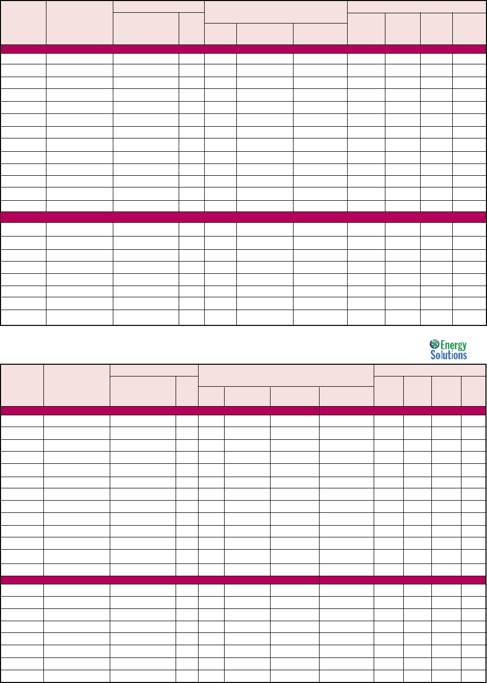
Capacities
Hot Gas Defrost Capabilities
HGT Hot Gas Defrost Models 60 Hz. with Shaded Pole Motors
Capacity Fan Data Shaded Pole Motor Data Drain Pan Heater (Total Amps)*
HGT BTUH / Watts (Total Amps/Watts)
Model
10°F / 6°C TD
115/ 208-230/ 115/ 230/ 460/
Size
-20°F / -29°C SST
CFM / m3H No. HP 1/60 Watts 1/60 Watts Watts 1/60 1/60 1/60
6 FPI Models
HGT 035 3,500 700 1 1/15 1.8 1.0 300 2.6 1.3 0.7
1,025 1,189 116 122
HGT 040 4,000 700 1 1/15 1.8 1.0 300 2.6 1.3 0.7
1,170 1,189 116 122
HGT 047 4,700 650 1 1/15 1.8 1.0 300 2.6 1.3 0.7
1,380 1,104 116 122
HGT 065 6,500 1,400 2 1/15 3.6 2.0 600 5.2 2.6 1.3
1,900 2,379 232 244
HGT 075 7,500 1,300 2 1/15 3.6 2.0 600 5.2 2.6 1.3
2,200 2,209 232 244
HGT 090 9,000 1,300 2 1/15 3.6 2.0 600 5.2 2.6 1.3
2,640 2,209 232 244
HGT 120 12,000 2,100 3 1/15 5.4 3.0 900 7.8 3.9 2.0
3,520 3,568 348 366
HGT 140 14,000 1,950 3 1/15 5.4 3.0 900 7.8 3.9 2.0
4,100 3,313 348 366
HGT 160 16,000 2,600 4 1/15 7.2 4.0 1,200 10.4 5.2 2.6
4,690 4,418 464 488
HGT 180 18,000 2,600 4 1/15 7.2 4.0 1,200 10.4 5.2 2.6
5,280 4,418 464 488
HGT 200 20,000 3,250 5 1/15 9.0 5.0 1,500 13.0 6.5 3.3
5,860 5,522 580 610
HGT 240 24,000 3,900 6 1/15 10.8 6.0 1,800 15.7 7.8 3.9
7,030 6,627 696 732
HGT 280 28,000 3,900 6 1/15 10.8 6.0 1,800 15.7 7.8 3.9
8,200 6,627 696 732
4 FPI Models
HGT 041 4,100 690 1 1/15 1.8 1.0 300 2.6 1.3 0.7
1,200 1,172 116 122
HGT 068 6,800 1,380 2 1/15 3.6 2.0 600 5.2 2.6 1.3
2,000 2,345 232 244
HGT 080 8,000 1,380 2 1/15 3.6 2.0 600 5.2 2.6 1.3
2,340 2,345 232 244
HGT 102 10,200 2,170 3 1/15 5.4 3.0 900 7.8 3.9 2.0
2,990 3,687 348 366
HGT 136 13,600 2,760 4 1/15 7.2 4.0 1,200 10.4 5.2 2.6
3,990 4,690 464 488
HGT 170 17,000 3,450 5 1/15 9.0 5.0 1,500 13.0 6.5 3.3
4,980 5,862 580 610
HGT 204 20,400 4,140 6 1/15 10.8 6.0 1,800 15.7 7.8 3.9
5,980 7,035 696 732
HGT 235 23,500 4,140 6 1/15 10.8 6.0 1,800 15.7 7.8 3.9
6,880 7,035 696 732
HGT Hot Gas Defrost Models 60 Hz. with PSC Motors
Capacity Fan Data PSC, PSE-TE Motor Data
Drain Pan Heater (Total Amps)*
HGT BTUH / Watts (Total Amps/Watts)
Model
10°F / 6°C TD
115/ 208-230/ 460/ 115/ 230/ 460/
Size
-20°F / -29°C SST
CFM / m3H No. HP 1/60 Watts 1/60 Watts 1/60 Watts Watts 1/60 1/60 1/60
6 FPI Models
HGT 035 3,500 700 1 1/15 1.0 0.5 0.4 300 2.6 1.3 0.7
1,025 1,189 82 91 117
HGT 040 4,000 700 1 1/15 1.0 0.5 0.4 300 2.6 1.3 0.7
1,170 1,189 82 91 117
HGT 047 4,700 650 1 1/15 1.0 0.5 0.4 300 2.6 1.3 0.7
1,380 1,104 82 91 117
HGT 065 6,500 1,400 2 1/15 2.0 1.0 0.8 600 5.2 2.6 1.3
1,900 2,379 164 182 234
HGT 075 7,500 1,300 2 1/15 2.0 1.0 0.8 600 5.2 2.6 1.3
2,200 2,209 164 182 234
HGT 090 9,000 1,300 2 1/15 2.0 1.0 0.8 600 5.2 2.6 1.3
2,640 2,209 164 182 234
HGT 120 12,000 2,100 3 1/15 3.0 1.5 1.2 900 7.8 3.9 2.0
3,520 3,568 246 273 351
HGT 140 14,000 1,950 3 1/15 3.0 1.5 1.2 900 7.8 3.9 2.0
4,100 3,313 246 273 351
HGT 160 16,000 2,600 4 1/15 4.0 2.0 1.6 1,200 10.4 5.2 2.6
4,690 4,418 328 364 468
HGT 180 18,000 2,600 4 1/15 4.0 2.0 1.6 1,200 10.4 5.2 2.6
5,280 4,418 328 364 468
HGT 200 20,000 3,250 5 1/15 5.0 2.5 2.0 1,500 13.0 6.5 3.3
5,860 5,522 410 455 585
HGT 240 24,000 3,900 6 1/15 6.0 3.0 2.4 1,800 15.7 7.8 3.9
7,030 6,627 492 546 702
HGT 280 28,000 3,900 6 1/15 6.0 3.0 2.4 1800 15.7 7.8 3.9
8,200 6,627 492 546 702
4 FPI Models
HGT 041 4,100 690 1 1/15 1.0 0.5 0.4 300 2.6 1.3 0.7
1,200 1,172 82 91 117
HGT 068 6,800 1,380 2 1/15 2.0 1.0 0.8 600 5.2 2.6 1.3
2,000 2,345 164 182 234
HGT 080 8,000 1,380 2 1/15 2.0 1.0 0.8 600 5.2 2.6 1.3
2,340 2,345 164 182 234
HGT 102 10,200 2,170 3 1/15 3.0 1.5 1.2 900 7.8 3.9 2.0
2,990 3,687 246 273 351
HGT 136 13,600 2,760 4 1/15 4.0 2.0 1.6 1,200 10.4 5.2 2.6
3,990 4,690 328 364 468
HGT 170 17,000 3,450 5 1/15 5.0 2.5 2.0 1,500 13.0 6.5 3.3
4,980 5,862 410 455 585
HGT 204 20,400 4,140 6 1/15 6.0 3.0 2.4 1,800 15.7 7.8 3.9
5,980 7,035 492 546 702
HGT 235 23,500 4,140 6 1/15 6.0 3.0 2.4 1,800 15.7 7.8 3.9
6,880 7,035 492 546 702
* Optional with electric drain pan.

- 9 -
Capacities
50 HZ
50 HZ
50 Hz. Capabilities
LET/LLE Electric Defrost Models 50 Hz. with PSC Motors
ADT Air Defrost Models 50 Hz. with PSC Motors
Capacity Fan Dat a PSC, TSC-TE Motor Data (Total Amps)
BTUH / Watts
ADT 6°C TD 110/ 220/ 380/
Model Size -4°C SST CFM / m3H No. HP 1/50 Watts 1/50Watts 1/50Watts
ADT 040 3,800 670 1 1/15 1.0 0.5 0.4
1,112 1,117 68 65 82
ADT 052 4,940 630 1 1/15 1.0 0.5 0.4
1,445 1,070 68 65 82
ADT 065 6,175 586 1 1/15 1.0 0.5 0.4
1,807 995 68 65 82
ADT 070 6,650 1,315 2 1/15 2.0 1.0 0.8
1,946 2,234 136 130 164
ADT 090 8,550 1,260 2 1/15 2.0 1.0 0.8
2,502 2,142 136 130 164
ADT 104 9,880 1,260 2 1/15 2.0 1.0 0.8
2,891 2,142 136 130 164
ADT 120 11,400 1,170 2 1/15 2.0 1.0 0.8
3,335 1,989 136 130 164
ADT 130 12,350 1,170 2 1/15 2.0 1.0 0.8
3,613 1,989 136 130 164
ADT 140 13,300 1,891 3 1/15 3.0 1.5 1.2
3,891 3,213 204 195 246
ADT 156 14,820 1,891 3 1/15 3.0 1.5 1.2
4,336 3,213 204 195 246
ADT 180 17,100 1,756 3 1/15 3.0 1.5 1.2
5,003 2,984 204 195 246
ADT 208 19,760 2,521 4 1/15 4.0 2.0 1.6
5,781 4,284 272 260 328
ADT 260 24,700 2,927 5 1/15 5.0 2.5 2.0
7,226 4,973 340 325 410
ADT 312 29,640 3,512 6 1/15 6.0 3.0 2.4
8,672 5,967 408 390 492
ADT 370 35,150 3,512 6 1/15 6.0 3.0 2.4
10,284 5,967 408 390 492
Capacity Fan Data PSC, PSC-TE Motor Data (Total Amps/Watts) Defrost Heaters (Total AmpsWatts)
BTUH / Watts
LET/LLE 6°C TD 220/ 380 220/ 220/ 380/
Model Size -29°C SST CFM / m3H No. HP 1/50 Watts 1/50 Watts Watts 1/50 3/50 1/50
6 FPI Models
LET 035 3,325 630 1 1/15 0.5 0.4 823 3.7 2.2 1.6
974 1,070 65 82
LET 040 3,800 630 1 1/15 0.5 0.4 823 3.7 2.2 1.6
1,113 1,070 65 82
LET 047 4,465 586 1 1/15 0.5 0.4 823 3.7 2.2 1.6
1,308 995 65 82
LET 065 6,175 1,260 2 1/15 1.0 0.8 1,647 7.5 4.3 3.2
1,809 2,142 130 164
LET 075 7,125 1,170 2 1/15 1.0 0.8 1,647 7.5 4.3 3.2
2,087 1,989 130 164
LET 090 8,550 1,170 2 1/15 1.0 0.8 1,647 7.5 4.3 3.2
2,504 1,989 130 164
LET 120 11,400 1,891 3 1/15 1.5 1.2 2,470 11.2 6.5 4.9
3,339 3,213 195 246
LET 140 13,300 1,756 3 1/15 1.5 1.2 2,470 11.2 6.5 4.9
3,896 2,984 195 246
LET 160 15,200 2,341 4 1/15 2.0 1.6 3,294 15.0 8.6 6.5
4,452 3,978 260 328
LET 180 17,100 2,341 4 1/15 2.0 1.6 3,294 15.0 8.6 6.5
5,009 3,978 260 328
LET 200 19,000 2,927 5 1/15 2.5 2.0 4,117 18.7 10.8 8.1
5,565 4,973 325 410
LET 240 22,800 3,512 6 1/15 3.0 2.4 4,941 22.5 13.0 9.7
6,678 5,967 390 492
LET 280 26,600 3,512 6 1/15 3.0 2.4 4,941 22.5 13.0 9.7
7,791 5,967 390 492
4 FPI Models
LLE 041 3,895 621 1 1/15 0.5 0.4 823 3.7 2.2 1.6
1,141 1,056 65 82
LLE 068 6,460 1,243 2 1/15 1.0 0.8 1,647 7.5 4.3 3.2
1,892 2,111 130 164
LLE 080 7,600 1,243 2 1/15 1.0 0.8 1,647 7.5 4.3 3.2
2,226 2,111 130 164
LLE 102 9,690 1,954 3 1/15 1.5 1.2 2,470 11.2 6.5 4.9
2,838 3,320 195 246
LLE 136 12,920 2,485 4 1/15 2.0 1.6 3,294 15.0 8.6 6.5
3,784 4,223 260 328
LLE 170 16,150 3,107 5 1/15 2.5 2.0 4,117 18.7 10.8 8.1
4,731 5,279 325 410
LLE 204 19,380 3,728 6 1/15 3.0 2.4 4,941 22.5 13.0 9.7
5,677 6,334 390 492
LLE 235 22,325 3,728 6 1/15 3.0 2.4 4,941 22.5 13.0 9.7
6,539 6,334 390 492

- 10 -
50 HZ
* Optional with electric drain pan.
4 FPI Models
Capacities
Hot Gas Defrost Capabilities
HGT Hot Gas Defrost Models 50 Hz. with PSC Motors
Capacity Fan Data PSC, PSC-TE Motor Data (Total Amps/Watts) Defrost Heaters (Total Amps)*
BTUH / Watts
HGT 6°C TD 110/ 220/ 380/ 110/ 220/ 380/
Model Size -29°C SST CFM / m3H No. HP 1/50 Watts 1/50 Watts
1/50 Watts
Watts 1/50 3/50 1/50
6 FPI Models
HGT 035 3,325 630 1 1/15 1.0 0.5 0.4 275 2.5 1.3 0.6
974 1,070 68 65 82
HGT 040 3,800 630 1 1/15 1.0 0.5 0.4 275 2.5 1.3 0.6
1,113 1,070 68 65 82
HGT 047 4,465 586 1 1/15 1.0 0.5 0.4 275 2.5 1.3 0.6
1,308 995 68 65 82
HGT 065 6,175 1,260 2 1/15 2.0 1.0 0.8 549 5.0 2.5 1.1
1,809 2,142 136 130 164
HGT 075 7,125 1,170 2 1/15 2.0 1.0 0.8 549 5.0 2.5 1.1
2,087 1,989 136 130 164
HGT 090 8,550 1,170 2 1/15 2.0 1.0 0.8 549 5.0 2.5 1.1
2,504 1,989 136 130 164
HGT 120 11,400 1,891 3 1/15 3.0 1.5 1.2 823 7.5 3.7 1.6
3,339 3,213 204 195 246
HGT 140 13,300 1,756 3 1/15 3.0 1.5 1.2 823 7.5 3.7 1.6
3,896 2,984 204 195 246
HGT 160 15,200 2,341 4 1/15 4.0 2.0 1.6 1098 10.0 5.0 2.2
4,452 3,978 272 260 328
HGT 180 17,100 2,341 4 1/15 4.0 2.0 1.6 1098 10.0 5.0 2.2
5,009 3,978 272 260 328
HGT 200 19,000 2,927 5 1/15 5.0 2.5 2.0 1372 12.5 6.2 2.7
5,565 4,973 340 325 410
HGT 240 22,800 3,512 6 1/15 6.0 3.0 2.4 1649 15.0 7.5 3.2
6,678 5,967 408 390 492
HGT 280 26,600 3,512 6 1/15 6.0 3.0 2.4 1649 15.0 7.5 3.2
7,791 5,967 408 390 492
HGT 041 3,895 621 1 1/15 1.0 0.5 0.4 275 2.5 1.3 0.6
1,141 1,056 68 65 82
HGT 068 6,460 1,243 2 1/15 2.0 1.0 0.8 549 5.0 2.5 1.1
1,892 2,111 136 130 164
HGT 080 7,600 1,243 2 1/15 2.0 1.0 0.8 549 5.0 2.5 1.1
2,226 2,111 136 130 164
HGT 102 9,690 1,954 3 1/15 3.0 1.5 1.2 823 7.5 3.7 1.6
2,838 3,320 204 195 246
HGT 136 12,920 2,485 4 1/15 4.0 2.0 1.6 1098 10.0 5.0 2.2
3,784 4,223 272 260 328
HGT 170 16,150 3,107 5 1/15 5.0 2.5 2.0 1372 12.5 6.2 2.7
4,731 5,279 340 325 410
HGT 204 19,380 3,728 6 1/15 6.0 3.0 2.4 1649 15.0 7.5 3.2
5,677 6,334 408 390 492
HGT 235 22,325 3,728 6 1/15 6.0 3.0 2.4 1649 15.0 7.5 3.2
6,539 6,334 408 390 492

- 11 -
6 FPI Models
4 FPI Models
Air Defrost Physical Data
Connections (Inches) Approx.
ADT No. of Coil External Net Wt.
Model Size Fans Inlet Suction* Equalizer Drain Lbs / kg
ADT 040 1 1/2 OD 5/8 ID 1/4 OD 3/4 MPT 28
13
ADT 052 1 1/2 OD 5/8 ID 1/4 OD 3/4 MPT 31
15
ADT 065 1 1/2 OD 7/8 ID 1/4 OD 3/4 MPT 34
16
ADT 070 2 1/2 OD 7/8 ID 1/4 OD 3/4 MPT 45
21
ADT 090 2 1/2 OD 7/8 ID 1/4 OD 3/4 MPT 48
22
ADT 104 2 1/2 OD 7/8 ID 1/4 OD 3/4 MPT 49
23
ADT 120 2 1/2 OD 7/8 ID 1/4 OD 3/4 MPT 51
24
ADT 130 2 1/2 OD 7/8 ID 1/4 OD 3/4 MPT 53
25
ADT 140 3 1/2 OD 7/8 ID 1/4 OD 3/4 MPT 63
29
ADT 156 3 1/2 OD 7/8 ID 1/4 OD 3/4 MPT 67
31
ADT 180 3 1/2 OD 7/8 ID 1/4 OD 3/4 MPT 69
32
ADT 208 4 1/2 OD 1-1/8 ID 1/4 OD 3/4 MPT 82
38
ADT 260 5 1/2 OD 1-1/8 ID 1/4 OD 3/4 MPT 103
47
ADT 312 6 1/2 OD 1-1/8 ID 1/4 OD 3/4 MPT 124
57
ADT 370 6 1/2 OD 1-3/8 ID 1/4 OD 3/4 MPT 127
58
* Suction connection is swedged to directly accept piping
Capacities
Physical Data
Electric Defrost Physical Data
Connections (Inches) Approx.
LET/LLE No. of Net Wt.
Model Size Fans Coil Inlet Suction* External Equalizer Drain Lbs / kg
LET 035 1 1/2 OD 5/8 ID 1/4 OD 3/4 MPT 24
11
LET 040 1 1/2 OD 5/8 ID 1/4 OD 3/4 MPT 26
12
LET 047 1 1/2 OD 5/8 ID 1/4 OD 3/4 MPT 29
14
LET 065 2 1/2 OD 5/8 ID 1/4 OD 3/4 MPT 43
20
LET 075 2 1/2 OD 7/8 ID 1/4 OD 3/4 MPT 45
21
LET 090 2 1/2 OD 7/8 ID 1/4 OD 3/4 MPT 48
22
LET 120 3 1/2 OD 7/8 ID 1/4 OD 3/4 MPT 60
28
LET 140 3 1/2 OD 7/8 ID 1/4 OD 3/4 MPT 62
29
LET 160 4 1/2 OD 1-1/8 ID 1/4 OD 3/4 MPT 81
37
LET 180 4 1/2 OD 1-1/8 ID 1/4 OD 3/4 MPT 84
39
LET 200 5 1/2 OD 1-1/8 ID 1/4 OD 3/4 MPT 101
46
LET 240 6 1/2 OD 1-1/8 ID 1/4 OD 3/4 MPT 121
55
LET 280 6 1/2 OD 1-1/8 ID 1/4 OD 3/4 MPT 124
57
LLE 041 1 1/2 OD 5/8 ID 1/4 OD 3/4 MPT 28
13
LLE 068 2 1/2 OD 7/8 ID 1/4 OD 3/4 MPT 44
21
LLE 080 2 1/2 OD 7/8 ID 1/4 OD 3/4 MPT 47
22
LLE 102 3 1/2 OD 7/8 ID 1/4 OD 3/4 MPT 59
27
LLE 136 4 1/2 OD 1-1/8 ID 1/4 OD 3/4 MPT 80
37
LLE 170 5 1/2 OD 1-1/8 ID 1/4 OD 3/4 MPT 100
46
LLE 204 6 1/2 OD 1-1/8 ID 1/4 OD 3/4 MPT 120
55
LLE 235 6 1/2 OD 1-1/8 ID 1/4 OD 3/4 MPT 123
56

- 12 -
Hot Gas Defrost Physical Data
HGT Connections (Inches) Approx.
Model No. of Coil External Hot Gas Net Wt.
Size Fans Inlet Suction Equalizer Drain Side Port Pan Conns. Lbs / kg
6 FPI Models
HGT 035 1 5/8 ODF 5/8 ID 1/4 OD 3/4 MPT 3/8 OD 5/8 OD 26
12
HGT 040 1 5/8 ODF 5/8 ID 1/4 OD 3/4 MPT 3/8 OD 5/8 OD 28
13
HGT 047 1 5/8 ODF 5/8 ID 1/4 OD 3/4 MPT 3/8 OD 5/8 OD 31
15
HGT 065 2 5/8 ODF 5/8 ID 1/4 OD 3/4 MPT 3/8 OD 5/8 OD 45
21
HGT 075 2 5/8 ODF 7/8 ID 1/4 OD 3/4 MPT 3/8 OD 5/8 OD 47
22
HGT 090 2 7/8 ODF 7/8 ID 1/4 OD 3/4 MPT 3/8 OD 5/8 OD 50
23
HGT 120 3 7/8 ODF 7/8 ID 1/4 OD 3/4 MPT 3/8 OD 5/8 OD 62
29
HGT 140 3 7/8 ODF 7/8 ID 1/4 OD 3/4 MPT 3/8 OD 5/8 OD 64
30
HGT 160 4 7/8 ODF 1-1/8 ID 1/4 OD 3/4 MPT 3/8 OD 5/8 OD 83
38
HGT 180 4 1-1/8 ODF 1-1/8 ID 1/4 OD 3/4 MPT 3/8 OD 5/8 OD 86
40
HGT 200 5 1-1/8 ODF 1 1/8 ID 1/4 OD 3/4 MPT 3/8 OD 5/8 OD 103
47
HGT 240 6 1-1/8 ODF 1 1/8 ID 1/4 OD 3/4 MPT 3/8 OD 5/8 OD 123
56
HGT 280 6 1-1/8 ODF 1-1/8 ID 1/4 OD 3/4 MPT 3/8 OD 5/8 OD 126
57
4 FPI Models
HGT 041 1 5/8 ODF 5/8 ID 1/4 OD 3/4 MPT 3/8 OD 5/8 OD 30
14
HGT 068 2 5/8 ODF 7/8 ID 1/4 OD 3/4 MPT 3/8 OD 5/8 OD 46
21
HGT 080 2 5/8 ODF 7/8 ID 1/4 OD 3/4 MPT 3/8 OD 5/8 OD 49
23
HGT 102 3 7/8 ODF 7/8 ID 1/4 OD 3/4 MPT 3/8 OD 5/8 OD 61
28
HGT 136 4 7/8 ODF 1-1/8 ID 1/4 OD 3/4 MPT 3/8 OD 5/8 OD 82
38
HGT 170 5 7/8 ODF 1-1/8 ID 1/4 OD 3/4 MPT 3/8 OD 5/8 OD 102
47
HGT 204 6 7/8 ODF 1-1/8 ID 1/4 OD 3/4 MPT 3/8 OD 5/8 OD 122
56
HGT 235 6 1-1/8 ODF 1-1/8 ID 1/4 OD 3/4 MPT 3/8 OD 5/8 OD 125
57
The standard design for the new Bohn Low Profile Evaporators will incorporate an efficient hot gas loop
in the drain pan. Utilizing a hot gas loop is ideal for hot gas defrost applications where high temperature
gas can be maintained to defrost both the evaporator drain pan and coil.
For applications where cooler (lower) temperature hot gas is used for defrosting, Bohn offers optional
electric heater elements in the drain pan to ensure quick and efficient defrost of the drain pan allowing
condensate to drain quickly, saving the hot gas for efficient evaporator coil defrost.
If the optional electric heating element drain pan is preferred, please specify when ordering, there is no
additional charge.
Physical Data
Physical Data
- 13 -
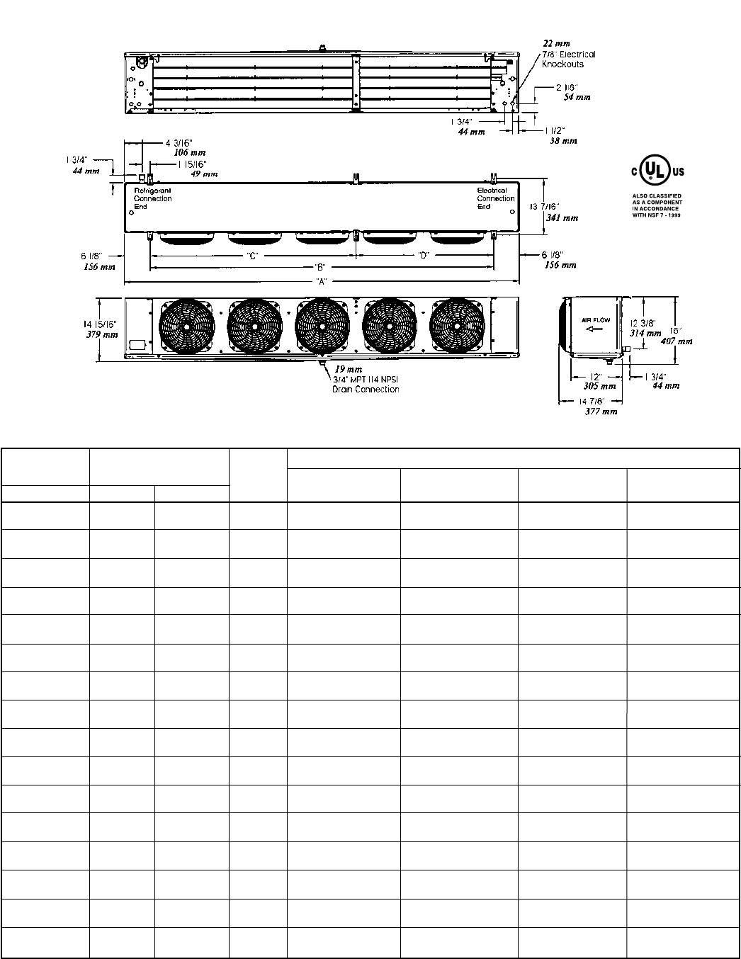
Dimensions
Dimensional Data
Dimensional Data For All Models
Air Defrost Electric and Hot Gas Dimensions (Inches / mm)
Models Defrost Models No. of
6 FPI 6 FPI 4 FPI Fans A B C D
040 035 — 1 29.50 17.25 — —
749.3 438.1
052 040 — 1 29.50 17.25 — —
749.3 438.1
065 047 041 1 29.50 17.25 — —
749.3 438.1
070 — — 2 45.50 33.25 — —
1,155.7 845.0
090 065 — 2 45.50 33.25 — —
1,155.7 845.0
104 — — 2 45.50 33.25 — —
1,155.7 845.0
120 075 068 2 45.50 33.25 — —
1,155.7 845.0
130 090 080 2 45.50 33.25 — —
1,155.7 845.0
140 120 102 3 61.50 49.25 — —
1,562.1 1,251.0
156 — — 3 61.50 49.25 — —
1,562.1 1,251.0
180 140 — 3 61.50 49.25 — —
1,562.1 1,251.0
208 160 — 4 77.50 65.25 — —
1,968.5 1,657.0
— 180 136 4 77.50 65.25 — —
1,968.5 1,657.0
260 200 170 5 93.50 81.25 48.63 32.63
2,374.9 2,064.0 1,235.1 828.7
312 240 204 6 109.50 97.25 48.63 48.63
2,781.3 2,470.0 1,235.1 1,235.1
370 280 235 6 109.50 97.25 48.63 48.63
2,781.3 2,470.0 1,235.1 1,235.1
NOTE: Hanger brackets will accept 3/8” / 9.5 mm hanger rods.
- 14 -
6 FPI
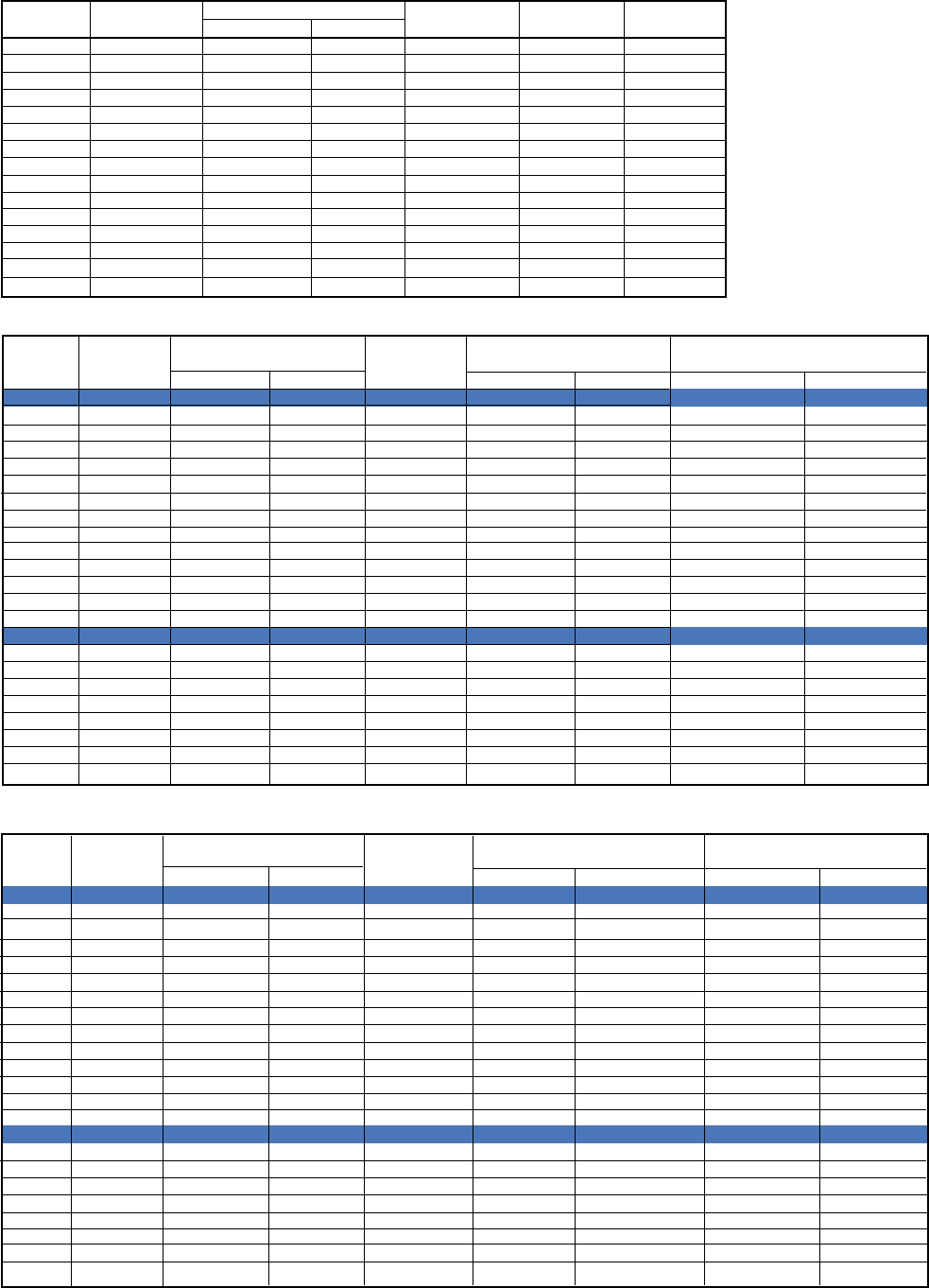
Nozzle Selection
Standard Nozzle Selection
Air Defrost
Distributor Tube (inches)
Fan # Model OD Length # Circuits R404A R-22
1 040 3/16 15 1 - -
1 052 3/16 15 1 - -
1 065 3/16 15 2 L-1/2 L-1/3
2 070 3/16 15 2 L-1/2 L-1/3
2 090 3/16 15 3 L-3/4 L-1/2
2 104 3/16 15 3 L-3/4 L-1/2
2 120 3/16 15 3 L-1 L-3/4
2 130 3/16 15 4 L-1 L-3/4
3 140 3/16 15 4 L-1 L-3/4
3 156 3/16 15 5 L-1 1/2 L-1
3 180 3/16 15 5 L-1 1/2 L-1
4 208 3/16 15 5 L-1 1/2 L-1
5 260 3/16 15 9 L-2 L-1 1/2
6 312 3/16 15 9 L-2 1/2 L-2
6 370 3/16 15 10 L-3 L-2
Electric Defrost
Low Temp. Medium Temp.
Distributor Tube (inches) -30°F to 0°F SST +10°F to +25°F SST
#Fans Model OD Length #Circuits R404A R-22 R404A R-226 FPI
1 035 3/16 15 2 L-1/2 L-1/4 L-1/3 L-1/4
1 040 3/16 15 2 L-1/2 L-1/4 L-1/3 L-1/4
1 047 3/16 15 2 L-1/2 L-1/3 L-1/3 L-1/3
2 065 3/16 15 4 L-3/4 L-1/2 L-1/2 L-1/2
2 075 3/16 15 4 L-1 L-3/4 L-3/4 L-1/2
2 090 3/16 15 5 L-1 L-3/4 L-3/4 L-1/2
3 120 3/16 15 5 L-1 1/2 L-1 L-1 L-3/4
3 140 3/16 15 6 L-1 1/2 L-1 L-1 1/2 L-1
4 160 3/16 15 8 L-2 L-1 L-1 1/2 L-1
4 180 3/16 15 10 L-2 L-1 1/2 L-1 1/2 L-1
5 200 3/16 15 9 L-2 1/2 L-1 1/2 L-2 L-1 1/2
6 240 3/16 15 9 L-2 1/2 L-2 L-2 L-1 1/2
6 280 3/16 15 10 L-3 L-2 L-2 1/2 L-2
4 FPI
1 041 3/16 15 2 L-1/2 L-1/3 L-1/3 L-1/4
2 068 3/16 15 4 L-3/4 L-1/2 L-1/2 L-1/3
2 080 3/16 15 4 L-1 L-3/4 L-3/4 L-1/2
3 102 3/16 15 5 L-1 L-3/4 L-3/4 L-3/4
4 136 3/16 15 8 L-1 1/2 L-1 L-1 L-3/4
5 170 3/16 15 8 L-2 L-1 1/2 L-1 1/2 L-1
6 204 3/16 15 8 L-2 1/2 L-1 1/2 L-2 L-1 1/2
6 235 3/16 15 10 L-2 1/2 L-2 L-2 L-1 1/2
Hot Gas Defrost
Low Temp. Medium Temp.
Distributor Tube (inches) -30°F to 0°F SST +10°F to +25°F SST
#Fans Model OD Length #Circuits R404A R-22 R404A R-22
6 FPI
1 035 1/4 15 2 J-1/2 J-1/4 J-1/3 J-1/4
1 040 1/4 15 2 J-1/2 J-1/3 J-1/3 J-1/4
1 047 1/4 15 2 J-3/4 J-1/3 J-1/2 J-1/4
2 065 1/4 15 4 J-1 J-1/2 J-3/4 J-1/3
2 075 1/4 15 4 J-1 J-3/4 J-3/4 J-1/2
2 090 1/4 15 5 G-1 1/2 G-3/4 G-3/4 G-1/2
3 120 1/4 15 5 G-1 1/2 G-1 G-1 G-3/4
3 140 1/4 15 6 G-2 G-1 G-1 1/2 G-1
4 160 1/4 15 8 G-2 G-1 1/2 G-1 1/2 G-1
4 180 1/4 15 10 E-2 1/2 E-1 1/2 E-1 1/2 E-1
5 200 1/4 15 9 E-2 1/2 E-2 E-2 E-1 1/2
6 240 1/4 15 9 E-3 E-2 E-2 E-1 1/2
6 280 1/4 15 10 E-4 E-2 1/2 E-2 1/2 E-2
4 FPI
1 041 1/4 15 2 J-1/2 J-1/3 J-1/3 J-1/4
2 068 1/4 15 4 J-1 J- 1/2 J-3/4 J-1/2
2 080 1/4 15 4 J-1 J-3/4 J-3/4 J-1/2
3 102 1/4 15 5 G-1 1/2 G-3/4 G-1 G-3/4
4 136 1/4 15 8 G-2 G-1 G-1 1/2 G-1
5 170 1/4 15 8 G-2 G-1 1/2 G-1 1/2 G-1
6 204 1/4 15 8 G-2 1/2 G-2 G-2 G-1 1/2
6 235 1/4 15 10 E-3 E-2 E-2 E-1 1/2
- 15 -
Recommendation is that both check valve kits are ordered:
(For hot gas models with the hot gas loop drain pan ONLY)
Note: The drain pan check valve kit can be ordered as an independent item. But the suction line check valve kit
must be ordered with the drain pan check valve kit in order to complete the piping.
The Hot Gas unit coolers can be used in reverse cycle hot gas defrost systems using multiple evaporators
connected to one condensing unit. Generally, not more than one-third of the system defrosts at one time.
During the reverse cycle defrost, the reversing valve; located in the compressor discharge line, diverts hot gas
through the suction line to the evaporator.
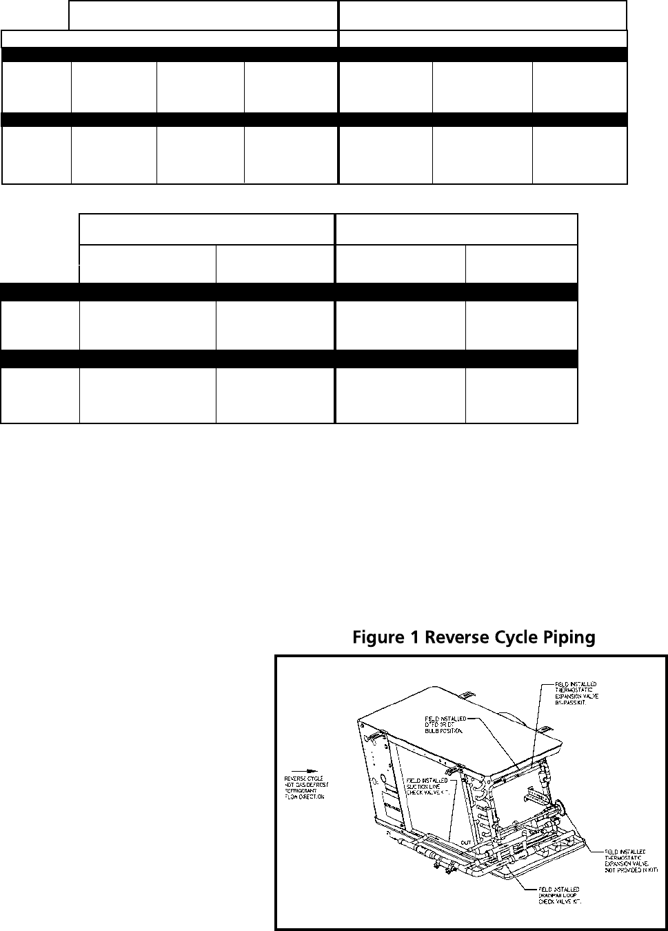
See piping view in Figure 1. The suction line
check valve directs the hot gas through the
drain pan loop which prevents condensate
in the pan from freezing. The hot gas exits
the loop at the pan loop outlet header and
enters the evaporator through the check
valve assembly. As the hot gas defrosts the
coil, heat is removed from the hot gas and
eventually it condenses into a liquid and
exits the coil at the distributor sideport.
The liquid then flows through the check
valve of the thermostatic expansion valve
bypass assembly, around the thermostatic
expansion valve, and into the system liquid
line. The liquid refrigerant then feeds
other evaporators on the cooling cycle,
evaporates, and returns to the compressor through their suction lines.
Note: When using the HOT GAS units on 0°F applications and below, an insulated drain pan is required.
SQE/SBF EG HFESC
52733701 52733704 52733707
52733702 52733705 52733708
52733703 52733706 52733709
52733701 52733704 52733707
52733702 52733705 52733708
52733703 52733706 52733709
TXV Bypass Assembly Kits TXV Bypass Assembly Kits
Ship Loose Factory Installed
HGT 6 FPI SQE/SBF EG HFESC
035 - 075 50169210 50169213 50169216
090 - 160 50169211 50169214 50169217
180 - 280 50169212 50169215 50169218T
4 FPI
041 - 080 50169210 50169213 50169216
102 - 204 50169211 50169214 50169217
235 50169212 50169215 50169218
Ship Loose Factory Installed
Drain Pan Loop Suction Line
Check Valve Kit Check Valve Kit
HGT 6 FPI
035 - 065 50169304 50169604
075 - 140 50169305 50169605
160 - 280 50169306 50169606
HGT 4 FPI
041 50169304 50169604
068 - 102 50169305 50169605
136 - 235 50169306 50169606
Reverse Cycle Kits
Hot Gas Reverse Cycle Kits
Drain Pan Loop Suction Line
Check Valve Kit Check Valve Kit
52733601 52733801
52733602 52733802
52733603 52733803
52733601 52733801
52733602 52733802
52733603 52733803
- 16 -
In the refrigeration cycle, the thermostatic expansion
valve bypass assembly check valve only allows
refrigerant flow through the thermostatic expansion
valve and into the evaporator coil. As the refrigerant
vapor exits the coil at the suction line, the check valve
of the drain pan loop check valve assembly prevents the
refrigerant vapor flow through the drain pan loop.
Factory engineered assemblies (kits) are available for
both ship loose and factory installed at an additional
cost to complete the reverse cycle piping and
components. The suction line check valve assembly
includes the suction line check valve and the piping for
both the suction line and the connection to the drain
pan loop inlet header. In order for the suction line
check valve assembly to be mounted, the drain pan loop
check valve assembly must be used. The drain pan loop
check valve assembly includes the check valve, suction
line tee and a bent pipe. The thermostatic expansion
valve bypass assembly option includes the check valve,
tee and necessary piping. In order for the thermostatic
expansion valve bypass assembly option to be complete,
a thermostatic expansion valve must be selected by the sales engineer. The thermostatic expansion valve bypass
assembly option is dependent on the body style of the thermostatic expansion valves which includes the Sporlan
SQE, SBF, EG and the Alco HFESC body styles. The factory installed thermostatic expansion valve bypass assembly
option must have the thermostatic expansion valve selection included on the order for the Hot Gas unit cooler.
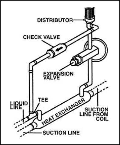
To increase the efficiency, higher performance and greater system protection, a heat exchanger may be beneficial
to the system. In order to use a heat exchanger, the thermostatic expansion valve bypass assembly option
must be modified. See the piping view in Figure 2. The modification includes rerouting the pipe from the
thermostatic expansion valve bypass check valve to the inlet connection of the liquid line to the heat exchanger.
A pipe needs to be routed from the liquid line outlet connection of the heat exchanger to the inlet connection
of the thermostatic expansion valve.
The electrical control option includes an adjustable defrost termination and fan delay control (DTFD) which is
standard. For an additional cost, an optional (2) control electrical system is available with one adjustable control
for defrost termination (DT) and one fixed control for the fan delay (FD). For both the DTFD and DT adjustable
controls, the remote bulb position is with the bulb strapped to the piping of the thermostatic expansion valve
bypass assembly option between the distributor sideport and the check valve. When the thermostatic expansion
valve bypass assembly is ship loose, the installer will need to position the remote bulb. When the thermostatic
expansion valve bypass assembly is factory installed, the remote bulb should already be properly installed.
Figure 2. Typical Liquid Line Bypass Kit
(Shown assembled and modified for heat exchanger)
Reverse Cycle Kits
Hot Gas Reverse Cycle Kits (cont.)
- 17 -
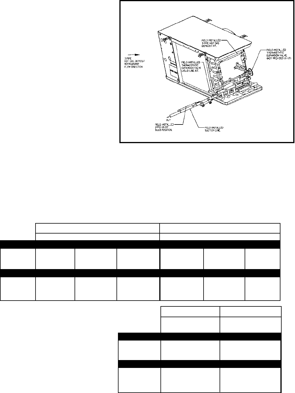
The Hot Gas defrost unit coolers conforms to
the standard 3-pipe hot gas system using a
check valve assembly, an electrical control to
terminate the defrost, and a hot gas solenoid
valve. The check valve assembly transports
the hot gas between the drain pan loop and
the sideport distributor of the coil. The check
valve assembly kit is available for ship loose or
factory installed for an additional cost. The
electrical control option includes an adjust-
able defrost termination and fan delay control
(DTFD) which is standard. An optional (2)
control electrical system is available with one
adjustable control for defrost termination
(DT) and one fixed control for the fan delay
(FD) for an additional cost. For both the
DTFD and DT adjustable controls, the remote
bulb position is with the bulb strapped to
the suction line to insure a complete defrost.
The remote bulb is positioned by the installer.
The hot gas solenoid valve must be ordered
separately and will be ship loose. The termostatic expansion valve could be ordered separately and ship loose or
the thermostatic expansion valve could be factory installed with a liquid line for an additional cost. The liquid line
is designed for the body styles of the Sporlan SQE, SBF, EG and the Alco HFESC thermostatic expansion valves. The
thermostatic expansion valve needs to be selected by the sales engineer. In a typical 3-pipe, multiple evaporator
system, the compressor discharge defrosts the evaporator. The liquid/vapor mixture of refrigerant after defrost,
however, returns to the common suction line of the system. In order to provide sufficient re-evaporation of the
liquid vapor mixture and sufficient heat for defrost, no more than one-third of the system should be defrosted at
one time. Some means of control in the 3-pipe hot gas system should be supplied to regulate the large amount of
liquid returning to the compressor, Refrigerant slugging can otherwise damage the compressor.
When using the HOT GAS units on 0°F
applications and below, an insulated
drain pan is required.
TXV Liquid Line TXV Liquid Line
Ship Loose Factory Installed
Factory Installed
Ship Loose
Drain Pan Loop Drain Pan Loop
Check Valve Kit Check Valve Kit
HGT 6 FPI
035 - 075 50169504 52739601
090 - 160 50169505 52739602
180 - 280 50169506 52739603
HGT 4 FPI
041 - 080 50169504 52739601
102 - 204 50169505 52739602
235 50169506 52739603
For Hot Gas models with the Hot Gas loop drain pan only
Hot Gas Defrost
3-Pipe Hot Gas Defrost
HGT 6 FPI SQE/SBF EG HFESC SQE/SBF EG HFESC
035 - 075 50169410 50169413 50169416 52733901 52733904 52733907
090 - 160 50169411 50169414 50169417 52733902 52733905 52733908
180 - 280 50169412 50169415 50169418 52733903 52733906 52733909
HGT 4 FPI
041 - 080 50169410 50169413 50169416 52733901 52733904 52733907
102 - 204 50169411 50169414 50169417 52733902 52733905 52733908
235 50169412 50169415 50169418 52733903 52733906 52733909
- 18 -
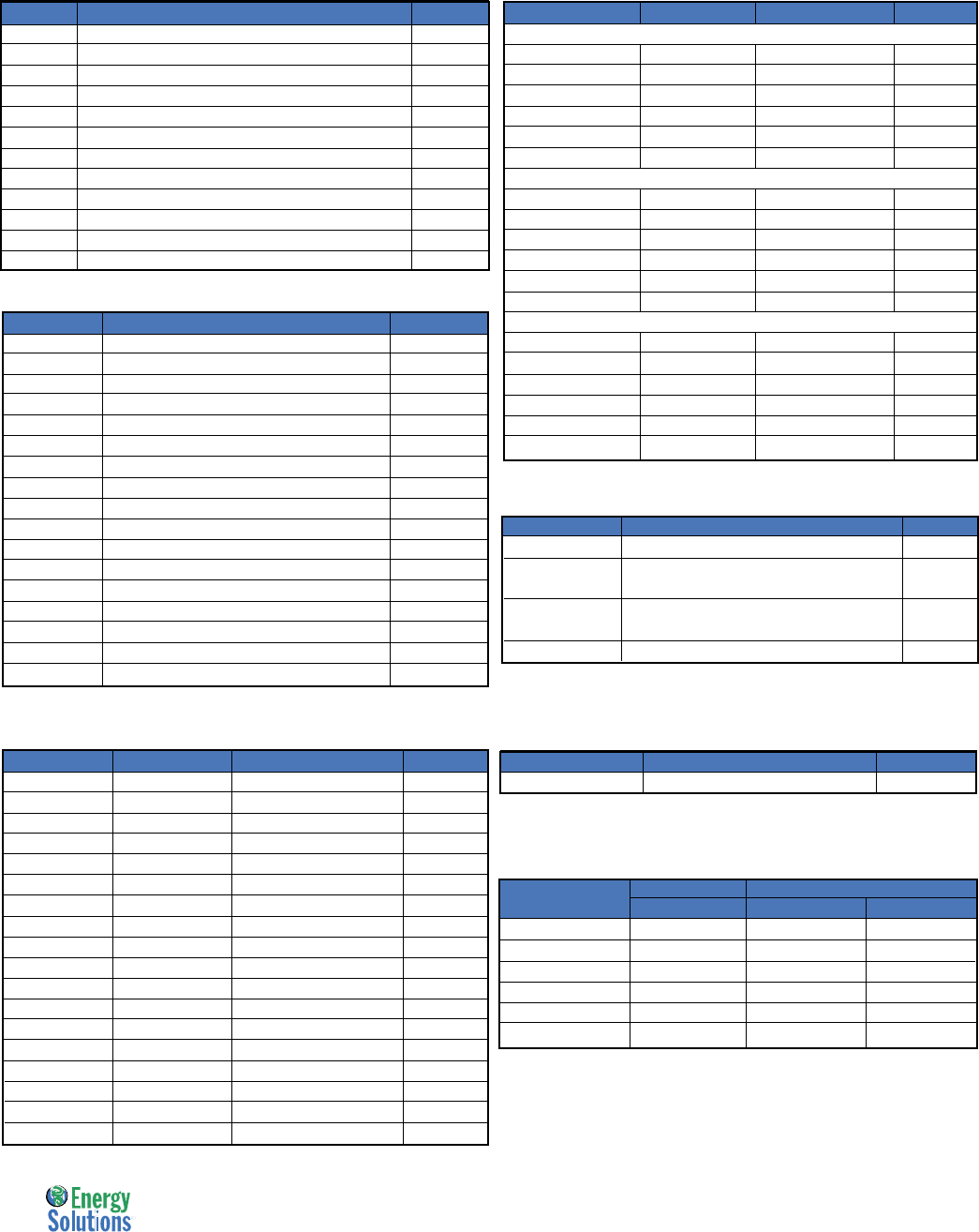
Replacement Parts
Replacement Parts
Cabinet Components
Part # Description No. of Fans
40480101 Drain Pan Air & Hot Gas Defrost 1
40480201 Drain Pan Air & Hot Gas Defrost 2
40480301 Drain Pan Air & Hot Gas Defrost 3
40480401 Drain Pan Air & Hot Gas Defrost 4
40480501 Drain Pan Air & Hot Gas Defrost 5
40480601 Drain Pan Air & Hot Gas Defrost 6
40480103 Drain Pan Electric Defrost 1
40480205 Drain Pan Electric Defrost 2
40480305 Drain Pan Electric Defrost 3
40480403 Drain Pan Electric Defrost 4
40480503 Drain Pan Electric Defrost 5
40480603 Drain Pan Electric Defrost 6
40880801 Access Panel - Elect 1-6
40880701 Access Panel - Refrig 1-6
40880901 Back Panel - Refrig 1-6
40881001 Back Panel - Elect 1-6
40881201 End Panel - Hot Gas Refrig 1-6
Motor / Fan Blade / Fan Guards
Part # Description No. Fans
25300101 Motor 115/1/60 Shaded Pole 1-6
25300201 Motor 208-230/1/60 Shaded Pole 1-6
25309501 Motor 115/1/60 Totally Enclosed PSC (110/1/50) 1-6
25309601 Motor 208-230/1/60 Totally Enclosed PSC 1-6
25309701 Motor 460/1/60 Totally Enclosed PSC 1-6
25309801 Motor 208-230/1/60 PSC (220/1/50) 1-6
25308701 Motor 460/1/60 PSC (380/1/50) 1-6
5140C Fan Blade 1-6
37000701 Fan Guard - Molded 1-6
37000601 Fan Guard - Wire 1-6
23104901 Motor mount used with 115 & 208-230v motors 1-6
23103301 Motor mount used with 460v motors 1-6
Electric Defrost
Part # Desc. Voltage No. Fans
Coil Heater
24752001 300 W 208-230/1/60 1
24752002 600 W 208-230/1/60 2
24752003 900 W 208-230/1/60 3
24752004 1200 W 208-230/1/60 4
24752005 1500 W 208-230/1/60 5
24752006 1800 W 208-230/1/60 6
Bottom Coil Heater
24752401 150W 208-230/1/60 1
24752402 300W 208-230/1/60 2
24752403 450W 208-230/1/60 3
24752404 600W 208-230/1/60 4
24752405 750W 208-230/1/60 5
24752406 900W 208-230/1/60 6
Drain Pan Heater
24752501 150W 208-230/1/60 1
24752502 300W 208-230/1/60 2
24752503 450W 208-230/1/60 3
24752504 600W 208-230/1/60 4
24752505 750W 208-230/1/60 5
24752506 900W 208-230/1/60 6
Electrical Components
Part # Description No. Fans
22512601 Terminal Strip 1 - 6
5709L Defrost Termination / Fan Delay
- Klixon Type 1 - 6
4267-W Defrost Termination / Fan Delay
- Adjustable Type 1 - 6
5708L Heater Safety - Klixon Type 1 - 6
Part # Description Voltage No. Fans
24752101 300 W 115/1/60 1
24752102 600 W 115/1/60 2
24752103 900 W 115/1/60 3
24752104 1200 W 115/1/60 4
24752105 1500 W 115/1/60 5
24752106 1800 W 115/1/60 6
24752201 300 W 208-230/1/60 1
24752202 600 W 208-230/1/60 2
24752203 900 W 208-230/1/60 3
24752204 1200 W 208-230/1/60 4
24752205 1500 W 208-230/1/60 5
24752206 1800 W 208-230/1/60 6
24752301 300 W 460/1/60 1
24752302 600 W 460/1/60 2
24752303 900 W 460/1/60 3
24752304 1200 W 460/1/60 4
24752305 1500 W 460/1/60 5
24752306 1800 W 460/1/60 6
Drain Fittings
Part # Description No. Fans
26925101 Drain Fitting Kit 1 - 6
No. Fans Air Defrost Electric & Hot Gas
6 FPI 6 FPI 4FPI
1 040-065 035-047 041
2 070-130 065-090 068-080
3 140-180 120-140 102
4 208 160-180 136
5 260 200 170
6 312-370 240-280 204-235
PSC Motors are an Energy Solutions option and are optimized to
help you save money by increasing energy efficiency.
Hot Gas Defrost – Electric Drain Pan Option
Drain Pan Heater (1 per unit)
- 19 -
NOTES
Notes
Notes

Since product improvement is a continuing effort,
we reserve the right to make changes in specifications without notice.
Visit us online at www.heatcraftrpd.com for technical literature online.
A Brand of Heatcraft Refrigeration Products LLC
2175 West Park Place Blvd. • Stone Mountain, GA 30087
770.465.5600 • Fax: 770.465.5990
www.heatcraftrpd.com
