Collis SMARTLINKBOX SmartCard Testing Terminal User Manual SmartLink Box
Collis B.V. SmartCard Testing Terminal SmartLink Box
UserManual.wiki
>
Collis
>
SMARTLINKBOX User Manual
manual
Navigation menu
Upload a User Manual
Namespaces
Wiki Guide
HTML
PDF
Info
Views
User Manual
Discussion / Help
Navigation


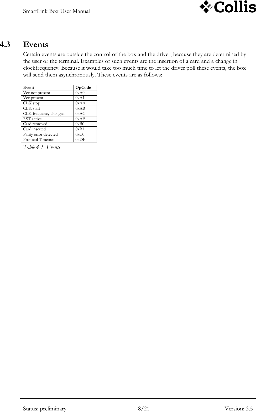
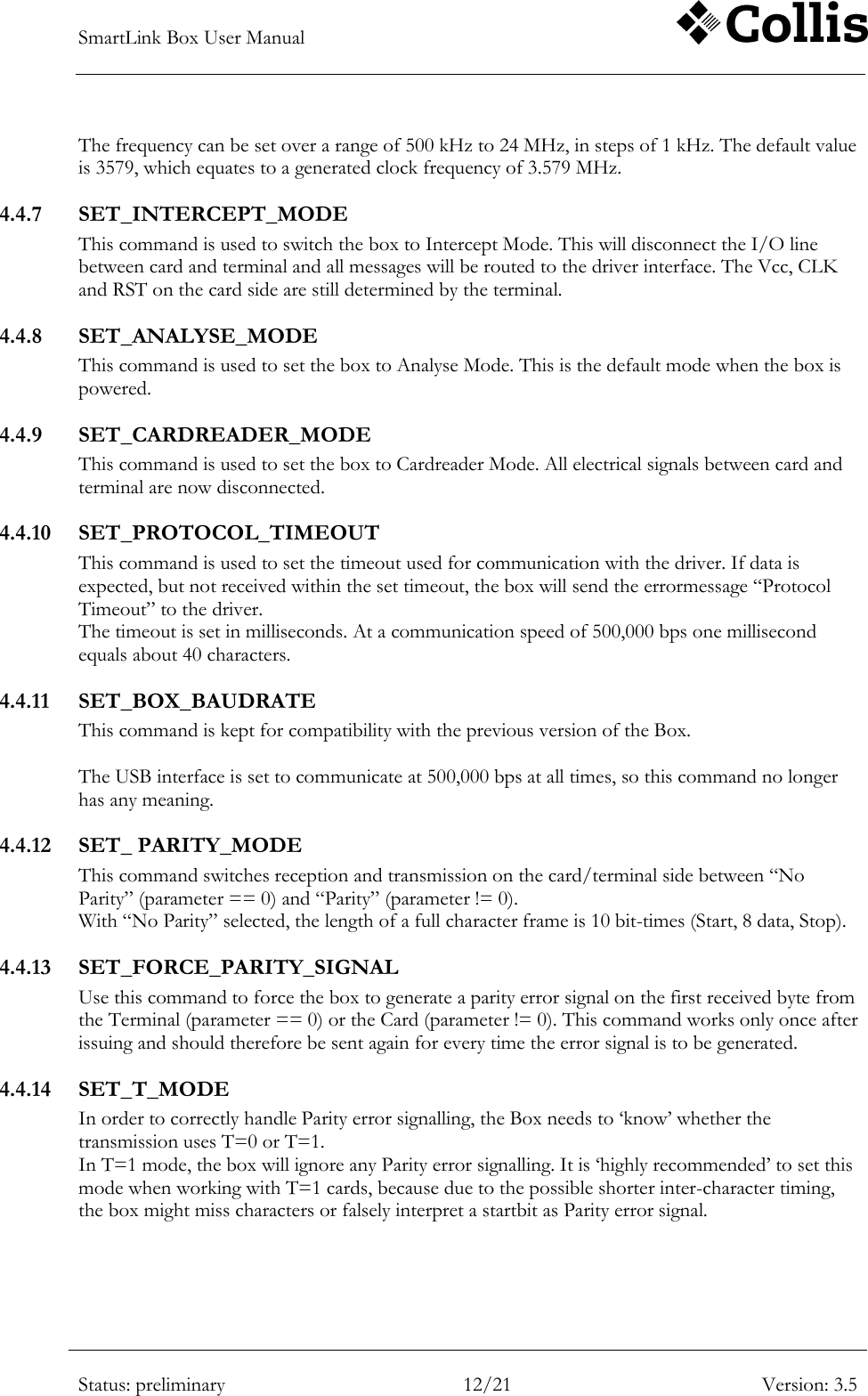
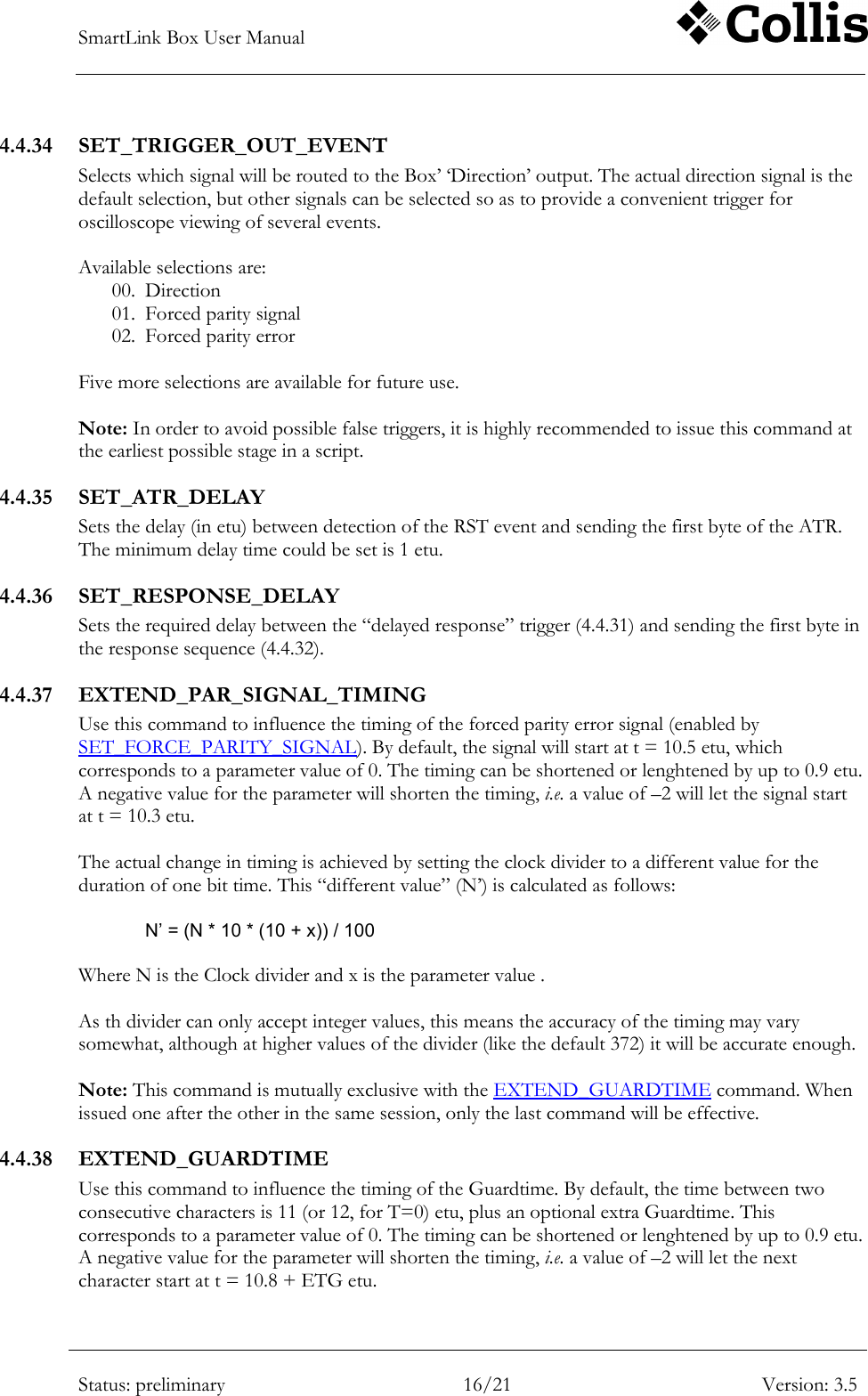
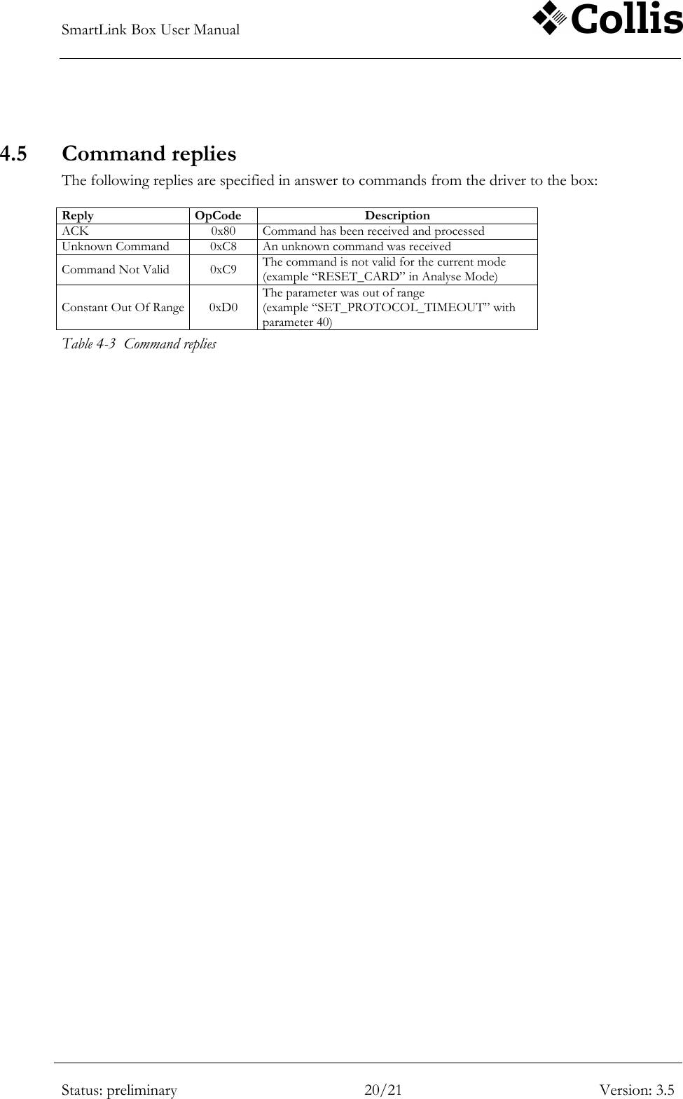
![SmartLink Box User Manual Status: preliminary 10/21 Version: 3.5 Command 5 OpCode Data 6 Unit 7 Range 8 Default value Applicable 9 SET_DEFAULT_DIVIDER 0x1D uint 1 ~ 1023 372 always SET_NO_PPS 0x1E N/A off always SET_FORCE_PAR_COUNT 0x1F uchar characters 0 ~ 255 0 Intercept and Cardreader Mode SET_FORCE_PAR_NUMBER 0x20 uchar 1 ~ 255 1 Intercept and Cardreader Mode SET_ATR1 0x21 char[32] <empty> always SET_ATR2 0x22 char[32] <empty> always SET_TRIGGER_COUNT 0x25 uchar characters 0 ~ 255 <empty> Intercept and Cardreader Mode SET_DELAYED_RESPONSE 0x26 char[32] <empty> Intercept and Cardreader Mode SET_ATR_DELAY 0x2A uint etu 1 ~ 65523 12 always SET_RESPONSE_DELAY 0x2B uint etu 1 ~ 65523 12 Intercept and Cardreader Mode INITIALIZE_CARD 0x30 N/A Cardreader Mode DEINITIALIZE_CARD 0x31 N/A Cardreader Mode SWITCH_CLK 0x32 uchar 0 / 1 Cardreader Mode CLK_OFF_LEVEL 0x33 uchar 0 / 1 0 Cardreader Mode RESET_CARD 0x34 N/A Cardreader Mode SET_SUPPLY_VOLTAGE 0x36 uchar x 100 mV. 0 ~ 55 and „0xFF‟ 50 always SET_VCC_THRESHOLD 0x37 uchar x 100mV. 10 ~ 45 24 always SET_TIMESTAMP_EOT 0x38 uchar 0 / 1 0 always GET_TIMESTAMP 0x41 uint x 100 µs. 0 ~ 65535 always GET_MODE 0x48 uchar 0 ~ 2 always GET_PROTOCOL_TIMEOUT 0x4E uchar ms. 0 ~ 25 always GET_SOFTWARE_VERSION 0x51 uchar always GET_DIVISION_RATE 0x53 uint 0 ~ 1023 always GET_TERM_STATUS 0x60 uchar 0xA0 ~ 0xA1 always GET_CARD_STATUS 0x70 uchar 0xB0 ~ 0xB1 always GET_CLOCK_FREQUENCY 0x64 ulong Hz 0 ~ 32x106 always GET_BAUDRATE 0x65 ulong bps always GET_SUPPLY_VOLTAGE 0x66 uint x 100 mV 0 ~ 63 always GET_VCC_THRESHOLD 0x67 uchar x 100mV. 10 ~ 45 always GET_ATR_CHARACTER_DELAY 0x78 uint etu 1 ~ 65523 always GET_GUARDTIME 0x79 uint etu 1 ~ 65523 always GET_ATR1 0x71 char[32] always GET_ATR2 0x72 char[32] always GET_ATR_DELAY 0x7A uint etu 1 ~ 65523 always](https://usermanual.wiki/Collis/SMARTLINKBOX/User-Guide-1293119-Page-15.png)
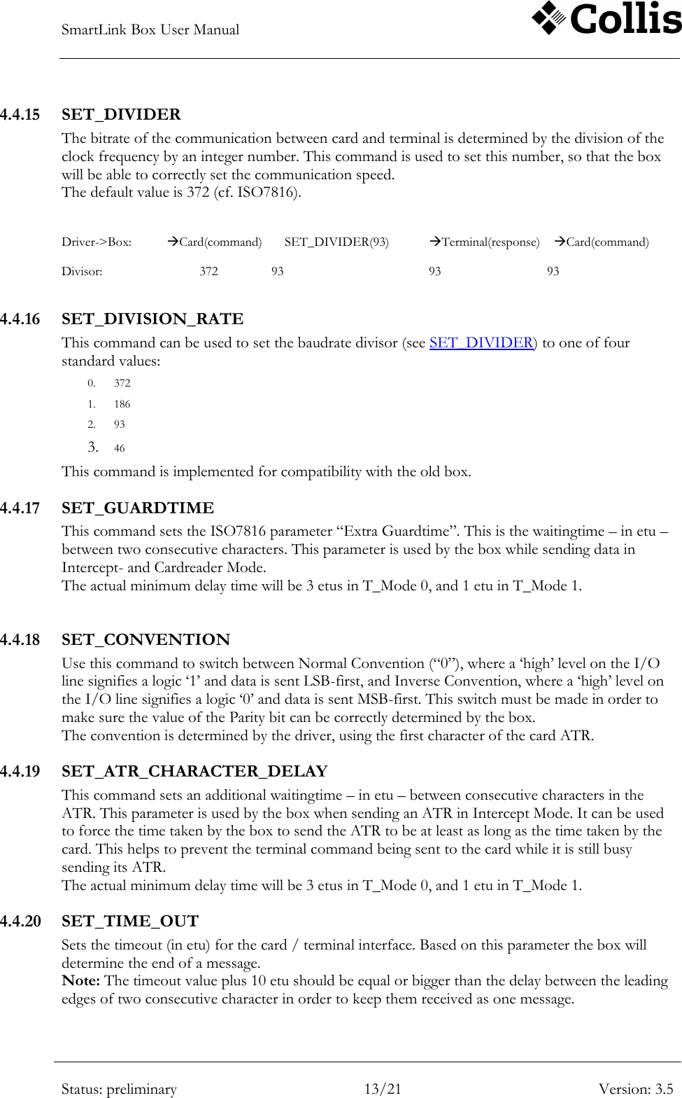
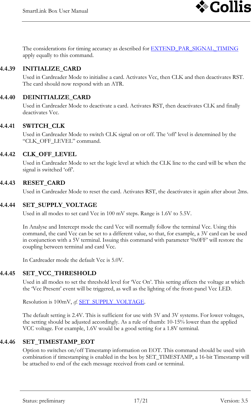
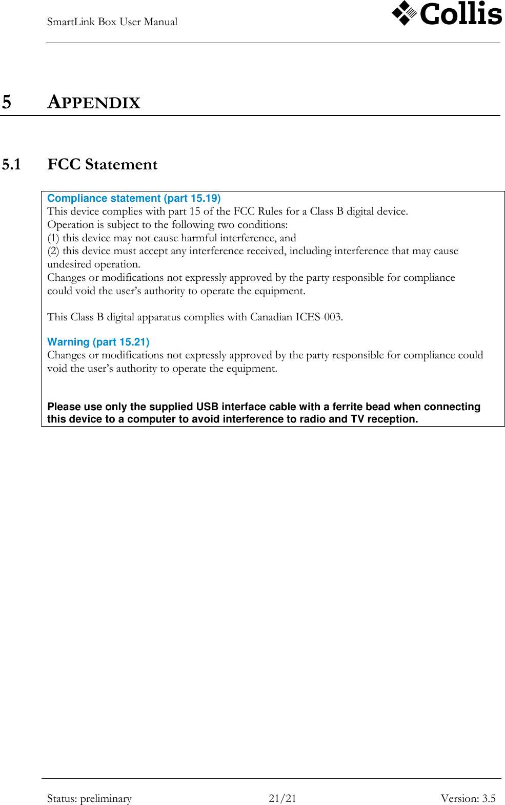
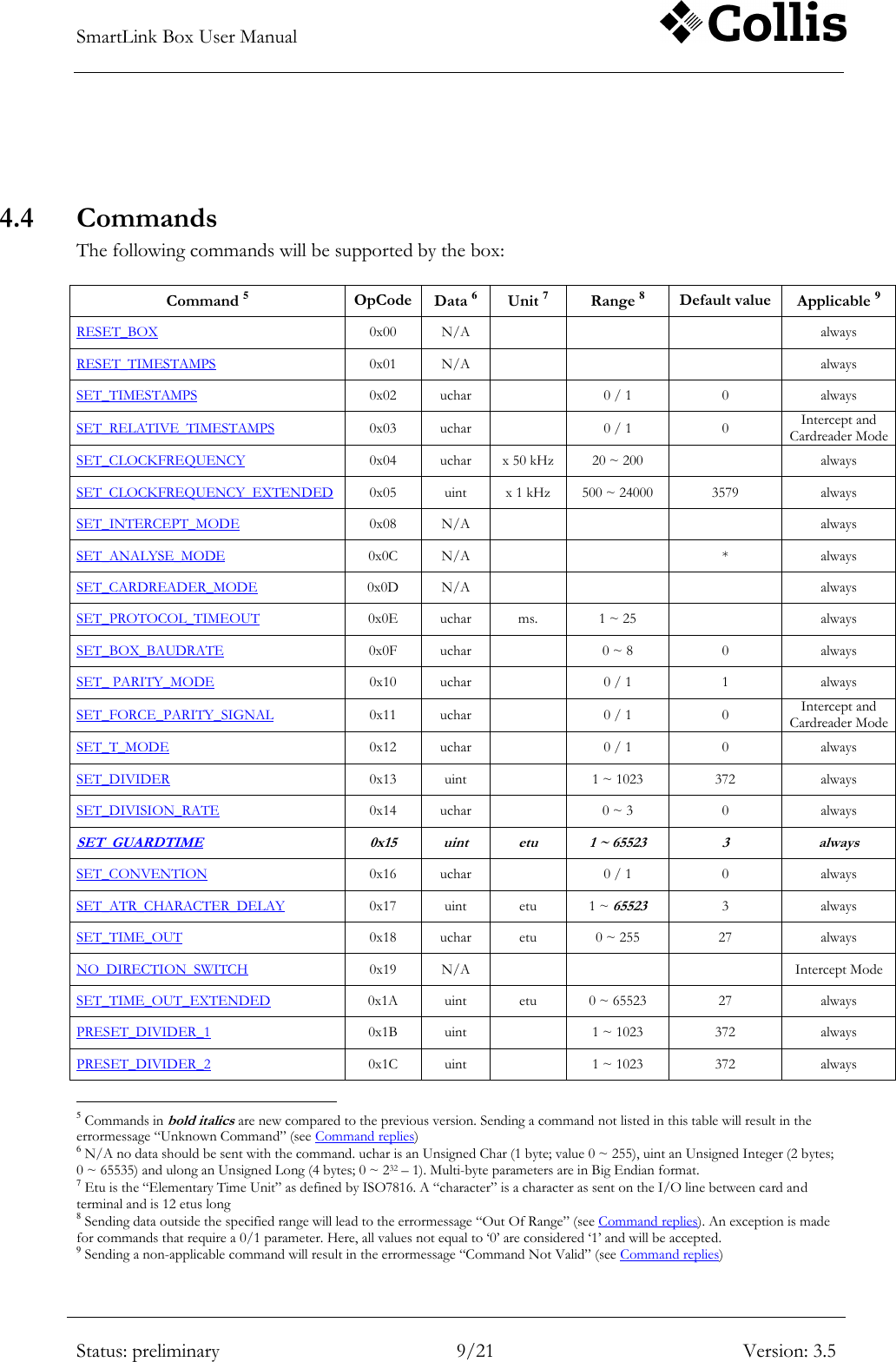
![SmartLink Box User Manual Status: preliminary 11/21 Version: 3.5 Command 5 OpCode Data 6 Unit 7 Range 8 Default value Applicable 9 GET_TIMEOUT_EOT 0x7B uint etu 0 ~ 65523 always GET_CPLD_VERSION 0x7C uchar[3] always START_SOFTWARE_DOWNLOAD 0xAA always START_CPLD_DOWNLOAD 0xCC always PROGRAM_CPLD 0xCD always Table 4-2 Command set 4.4.1 RESET_BOX This command is used to reset the box. The effect of this is that all settings will assume their default values and all buffers will be cleared. 4.4.2 RESET_TIMESTAMPS Use this command to reset the Timestamp counter. 4.4.3 SET_TIMESTAMPS This command switches sending of Timestamp information on (Data = 1) or off (Data = 0) When the Timestamps are „on‟, a 16-bit Timestamp will be added to each of the following messages: 1. Vcc on / off 2. Card in / out 3. RST active ( = „1‟ -> „0‟ !) 4. Message received from card or terminal 5. CLK on/off In case 4. one TimeStamp is sent that signifies the moment the first character of the message was received. 4.4.4 SET_RELATIVE_TIMESTAMPS This command switches between Relative Timestamps on (Data = 1) and off (Data = 0). Relative Timestamps differ from normal Timestamps in that a). they are only applicable in Intercept and Cardreader Modes and b). the Timestamp counter is reset at the last byte of each message that is sent to the Card or the Terminal. The actual Timestamp is still added to messages received (see SET_TIMESTAMPS), thus it enables the user to get an idea of the responsetime of either the Card or the Terminal. Note that the Timestamp reset coincides with the start of the last character sent by the box. The actual responsetime is therefore 2 charactertimes shorter than indicated by the Timestamp. 4.4.5 SET_CLOCKFREQUENCY This command sets the frequency of the CLK signal when the box is in Cardreader Mode. This command is a “Compatibility Command”, that is being implemented to maintain compatibility with the old box. 4.4.6 SET_CLOCKFREQUENCY_EXTENDED A different type of generator enables the new box to generate clockfrequencies over a wider range and with improved resolution. This command is added to make optimum use of this new generator and is the preferred command over SET_CLOCKFREQUENCY.](https://usermanual.wiki/Collis/SMARTLINKBOX/User-Guide-1293119-Page-16.png)