Comba Telecom Network Systems RS-5180 In-Building RF Distribution System User Manual file
Comba Telecom Ltd. In-Building RF Distribution System file
User Manual
RS-5180 CDMA800/1900
INDOOR DUAL BAND
FIBER-OPTIC REPEATER
USERS MANUAL

RS-5180CDMA800/1900 Dual Band Indoor Fiber Optic
Repeater
Comba Telecom
Edition 2.0 Date 2001-06 1 of 31
Contents
1. SYSTEM INTRODUCTION......................................................................3
1.1 SYSTEM APPLICATION...................................................................................................3
1.2 SYSTEM COMPOSITION..................................................................................................3
1.3 SYSTEM CONFIGURATION..............................................................................................4
1.4 SYSTEM APPEARANCE ...................................................................................................5
2. TECHNICAL EXPLANATIONS...............................................................7
2.1 SYSTEM COMPOSITION..................................................................................................7
2.2 SYSTEM FEATURES........................................................................................................8
2.3 SYSTEM FUNCTIONS......................................................................................................8
2.4 SPECIFICATIONS .........................................................................................................12
3. SYSTEM INSTALLATION .....................................................................13
3.1. INSTALLATION OF MASTER UNIT........................................................................ 13
3.2. INSTALLATION OF REMOTE UNIT..........................................................................20
4. SYSTEM CONNECTION AND DEBUT .................................................21
4.1. MASTER UNIT .....................................................................................................21
4.2. REMOTE UNIT ......................................................................................................26
5. USER SAFETY INFORMAT ION............................................................. 27
5.1 SYSTEM GROUNDING WELL........................................................................................27
5.2 CONFIRMING POWER SUPPLY.....................................................................................27

RS-5180CDMA800/1900 Dual Band Indoor Fiber Optic
Repeater
Comba Telecom
Edition 2.0 Date 2001-06 2 of 31
5.3 SUPPORT WITH SUFFICIENT LOAD-BEARING CAPACITY.............................................27
5.4 BE AWARE OF MECHANICAL DAMAGE.........................................................................27
5.5 PREVENTING LASER RADIATION..................................................................................27
5.6 DOWNLINK SIGNAL LEVEL INPUT FROM BS +20DBM.............................................28
6. SERVICE MANUAL...............................................................................29
6.1 OUR PROMISES ...........................................................................................................29
6.2 CONTACT DETAILS.......................................................................................................30
RS-5180CDMA800/1900 Dual Band Indoor Fiber Optic
Repeater
Comba Telecom
Edition 2.0 Date 2001-06 3 of 31
1. System Introduction
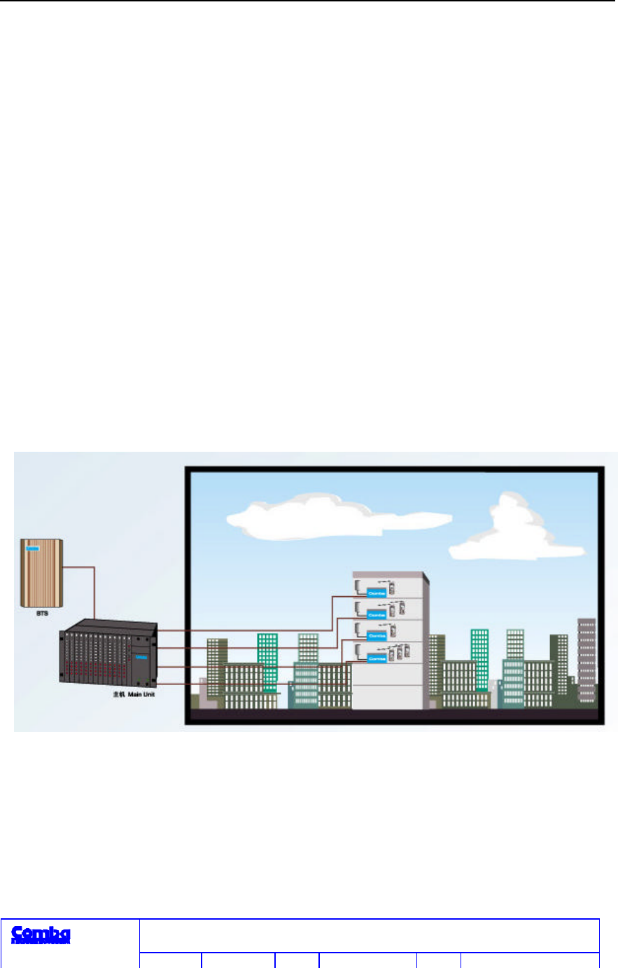
1.1 System Application
RS-5180 CDMA800/1900 dual band indoor fiber-optic repeater combines signals from
CDMA800/1900 BTSs, then transmits them to Remote Units which are finally transmitted by
antenna so as to expand signal coverage area.
RS-5180 CDMA800/1900 dual band indoor fiber-optic repeater is applicable to the indoor
signal coverage at areas such as large scale office building, high-rise hotels, large department
stores, exhibition halls, underground buildings, tunnels, airport etc.. Its application is shown in
figure 1.1-1.
Figure 1.1-1 Application of RS-5180
1.2 System Composition
RS 5180 CDMA800/1900 dual band indoor fiber-optic repeater is composed of master unit
(RS-5180-M) and Remote Unit (RS-5180-R).

RS-5180CDMA800/1900 Dual Band Indoor Fiber Optic
Repeater
Comba Telecom
Edition 2.0 Date 2001-06 4 of 31
1.2.1 Master Unit (RS-5180-M)
Ø 1 Master UnitRS-5180-S
Ø 1~4 Interface UnitsRS-5180-F. Quantity is determined by users.
Ø 1 power supply unitRS-5180-P
Ø A 19"6U cabinet. The above units are inserted into the cabinet.
Ø Options:chosen by users according to their needs
Alarm Unit (inserted into19"6U cabinet)
19" portable frame800mm high Tail fiber tray Master unit cover
1.2.2 Remote Unit (RS-5180-R)
A master unit can support up to16 Remote Units.
1.3 System Configuration
The Master Unit can be connected with at most 4 Interface Units. A Interface Unit can be
connected with 4 Remote Units. The whole system thus can be connected with 16 Remote Units
at most.
Each Remote Unit has 4 antenna ports. 16 Remote Units have 64 antenna ports. Each antenna
port can connect 2 antennas through a 2-way power splitters as needed. Therefore, the whole
system can connect up to128 antennas.
RS-5180CDMA800/1900 Dual Band Indoor Fiber Optic
Repeater
Comba Telecom
Edition 2.0 Date 2001-06 5 of 31
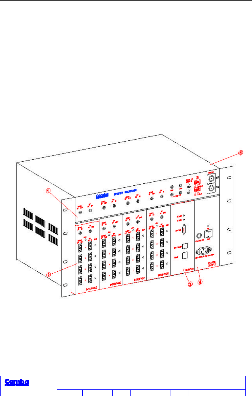
1.4 System Appearance
1.4.1 Master Unit (RS-5180-M)
The appearance of master unit is shown in figure 1.4-1. External dimensions (h×w×d) are 267×
442×364 mm3.
All units are in plug-and-play cabinet structure. 6U cabinet and panels of all units are made of
aluminum alloy with the surface conduction and oxidation finished.
Figure 1.4-1 Appearance of Master Unit
Master Unit Interface Unit Alarm Unit
Power Supply Unit 6U Cabinet
RS-5180CDMA800/1900 Dual Band Indoor Fiber Optic
Repeater
Comba Telecom
Edition 2.0 Date 2001-06 6 of 31
1.4.2 Remote Unit (RS-5180-M)
The appearance of Remote Unit is shown in figure 1.4-2.
The cabinet is made of aluminum alloy with the surface conduction and oxidation finished.
External dimensions (h×w×d) are 368×220×60 mm3.
Figure 1.4-2 Appearance of Remote Unit
RS-5180CDMA800/1900 Dual Band Indoor Fiber Optic
Repeater
Comba Telecom
Edition 2.0 Date 2001-06 7 of 31
2. Technical Explanations
2.1 System Composition
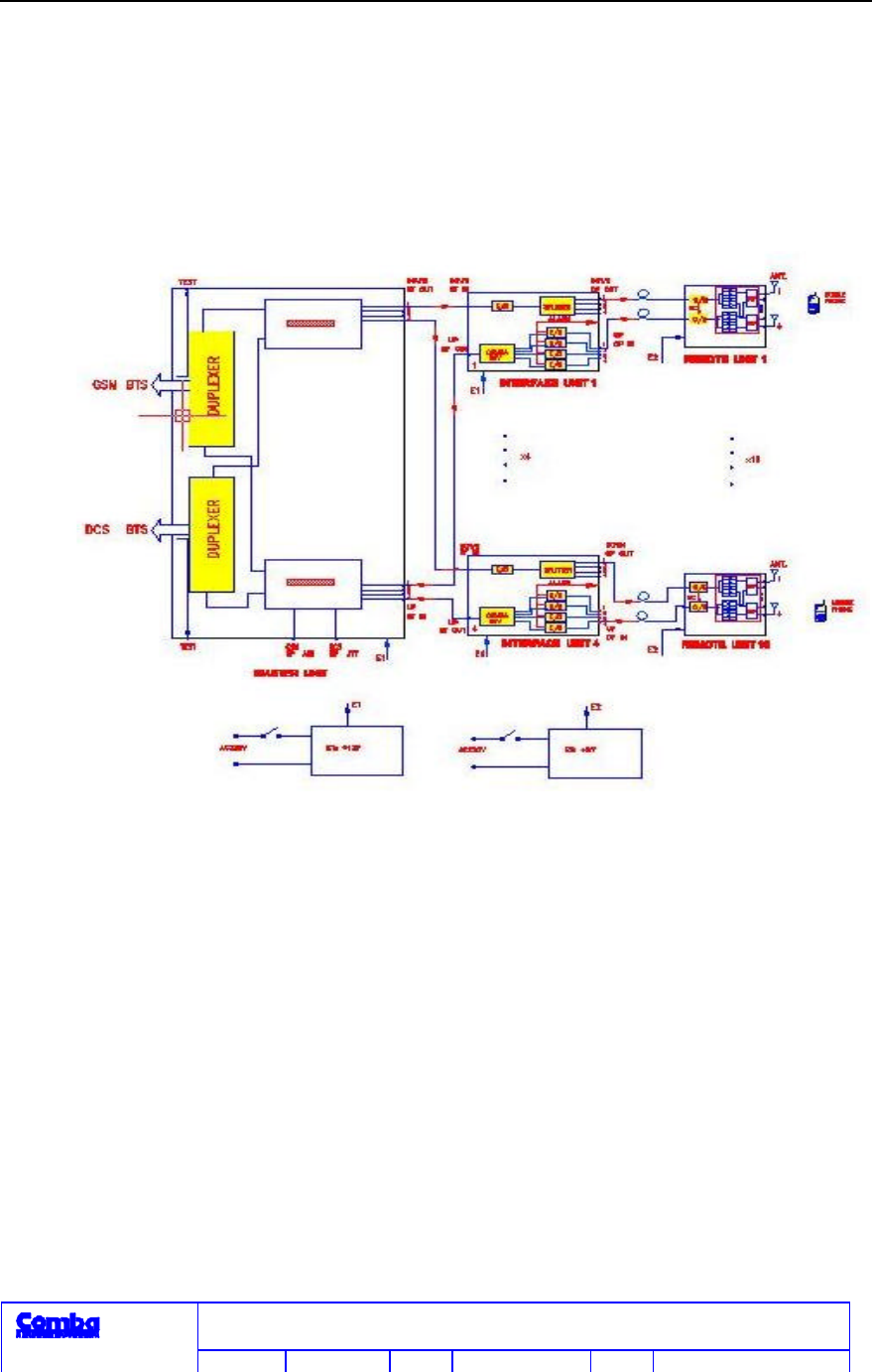
See figure 2.1-1.
Figure 2.1-1 System Composition of RS-5180
Transmission of uplink and downlink signals: RF Master Unit receives the downlink signal from
the BTSs of CDMA800 and CDMA1900. After combines, they are then changed to optical
signals through the optical interface unit and transmitted to the Remote Unit through optical
fiber. After changed to RF signals through Remote Unit, they are finally transmitted to Mobile
handsets by antenna. Vice versa, the uplink signal from user mobile is received by antenna. The
RF signals is then changed to optical signal by Remote Unit and transmitted to the master unit
through optical fiber. The optical signal then is changed to RF signals by the optical interface
unit of the master unit. Finally, after the CDMA800 and CDMA1900 dual band signals are

RS-5180CDMA800/1900 Dual Band Indoor Fiber Optic
Repeater
Comba Telecom
Edition 2.0 Date 2001-06 8 of 31
divided by the master unit, they are transmitted to CDMA800 and CDMA1900 BTSs.
2.2 System Features
n CDMA800/1900 dual band indoor optical fiber distribution coverage.
n Since optical fiber is the transmission media, it overcomes the drawbacks of indoor RF
routing difficulty and high loss.
n Plug and play system structure and flexible volume configuration can satisfy different
coverage requirements.
n Coverage end unit is small in size. Wall-hanging structure makes it easy to install,
flexible and concealed well, not affect indoor decoration and coverage area.
n Applicable to the indoor signal coverage of large-scale office buildings, high-rise hotels,
large-scale department stores, exhibition halls, underground buildings, tunnels and
airport.
n It has complete alarm function to monitor system working status. Alarm signal can be
sent to mobile network administration center through wire or wireless modem.
2.3 System Functions
2.3.1 Master Unit
Master Unit (RS-5180-M)
Main functions of the Master Unit include the level adjustment of the transmission and
received signals of BTS and the distribution of Interface Units. Master Unit can adjust the
CDMA800 uplink or CDMA1900 uplink RF signal level in the range of over 30dB for GSM
with step of 2dB and over 25dB for 1800 with step of 1dB. The uplink attenuation adjustment
dip switches are on the front panel. ALC function is to control the downlink signal level to
ensure the normal operation of Master Unit with downlink input signal level in the range of
+5dBm ~ +20dBm.
RS-5180CDMA800/1900 Dual Band Indoor Fiber Optic
Repeater
Comba Telecom
Edition 2.0 Date 2001-06 9 of 31
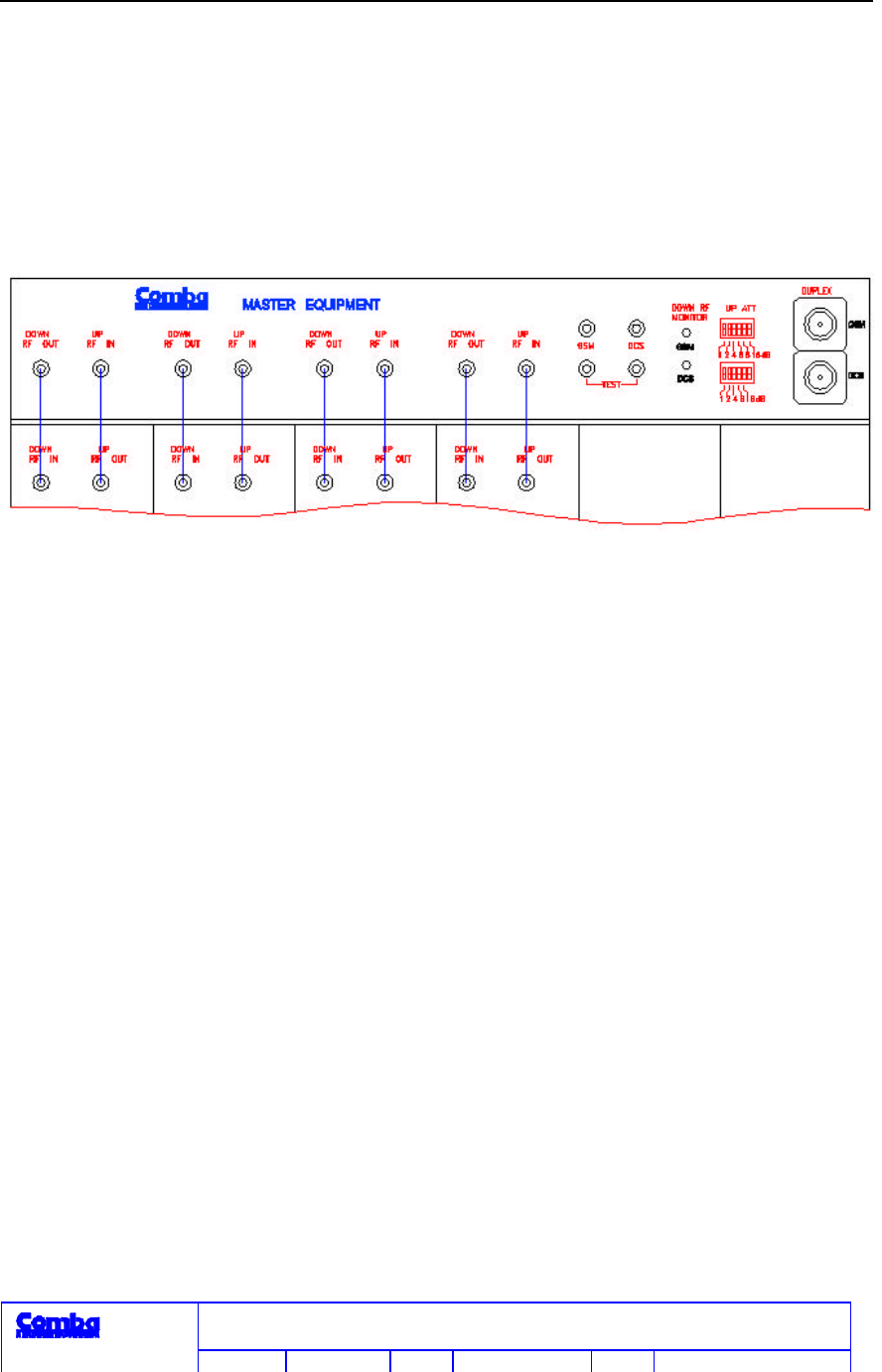
There are 4 downlink RF output ports and 4 uplink RF input ports on the front panel of the
Master Unit. Downlink and uplink are connected with 4 Interface Units through RF cable as
shown in figure 2.3-1.
Figure 2.3-1 Master Unit Panel Diagram
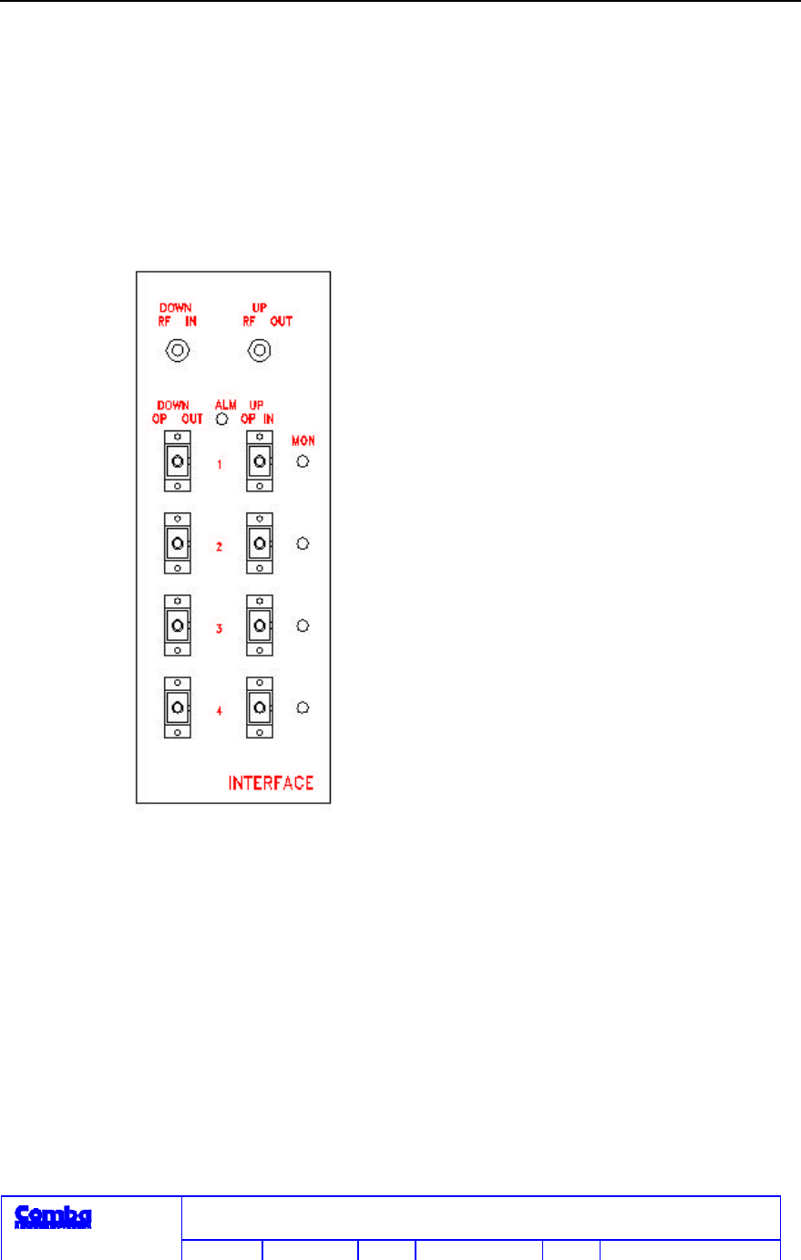
(1) Interface Unit (RS-5180-F)
Functions of Interface Unit include: uplink optical and electric conversion, showing the alarm
signal from Remote Unit and downlink optical dividing output.
1 Interface Unit has 4 couples of uplink optical input /downlink optical output ports to connect
with 4 Remote Units through optical fiber (figure 2.3-2).
Alarm function:
1. Each Interface Unit has a Optical Signal Transmitting Detection module. If no Optical
signals are sent, the red indicator on the panel will be on.
2. There is a Optical signal Receiving Detection module corresponding to each Remote Unit. If
no Optical signals are received, the correspondent will be off. When any Remote Unit or
RS-5180CDMA800/1900 Dual Band Indoor Fiber Optic
Repeater
Comba Telecom
Edition 2.0 Date 2001-06 10 of 31
Optical connection has trouble, the Remote Unit’s indicator light will automatically goes off.
Then the correspondent indicator on the panel of Interface Unit will be off. The indicators
next to the uplink optical signal in port on the panel correspond to the Remote Unit
connecting with.
Figure 2.3-3 Alarm Unit Panel
(2) Alarm Unit (RS-5180-MC)
When any Remote Unit (Interface Unit) has trouble, it will be indicated in LED and BTS
external alarm. It can also be checked through RS 232 interface. When communication unit
(MCC-001) is used, remote monitoring will be possible. Alarm unit is for occasional use only.

RS-5180CDMA800/1900 Dual Band Indoor Fiber Optic
Repeater
Comba Telecom
Edition 2.0 Date 2001-06 11 of 31
Panel explanations: As shown in figure 2.3-3.
RS-232 (BD9): standard RS232 port, used to connect notebook computer. Set and read
parameters, status check. The accompany digital port is designed for using in set up
only, not for daily operation and after set up no cable will be attached to this
port.
COMM (RJ45, 8-pin): communication unit port, used to connect communication unit to
actualize remote monitor. The accompany digital port is designed for using in set up
only, not for daily operation and after set up no cable will be attached to this
port.
BTS-ALARM (RJ45, 4-pin): BTS external alarm port, normal when the two pins in the middle
is opened, alarm when the two pins in the middle contact with each other. (occasionally used
only)
ALARM (LED): overall alarm indication. When any Remote Unit (Interface Unit) being
monitored has trouble, LED will turn to red, or it will be off.
2.3.2 Remote Unit (RS-5180-R)
Remote Unit receives the uplink signal from mobile handset in coverage area and amplifying it,
then converts it into optical signal and transmit to Interface Unit. At downlink direction, it
converts the optical signal sent from Interface Unit into RF signal and transmits it after
amplifying the power. RF receiving and transmitting module in Remote Unit has 4 duplex ports
to be connected with 4 antenna ports. Uplink and down link amplifiers have ALC function.
When duplex receiving and transmitting amplifier has trouble, the alarm circuit will
automatically turn the indicator off.
RS-5180CDMA800/1900 Dual Band Indoor Fiber Optic
Repeater
Comba Telecom
Edition 2.0 Date 2001-06 12 of 31
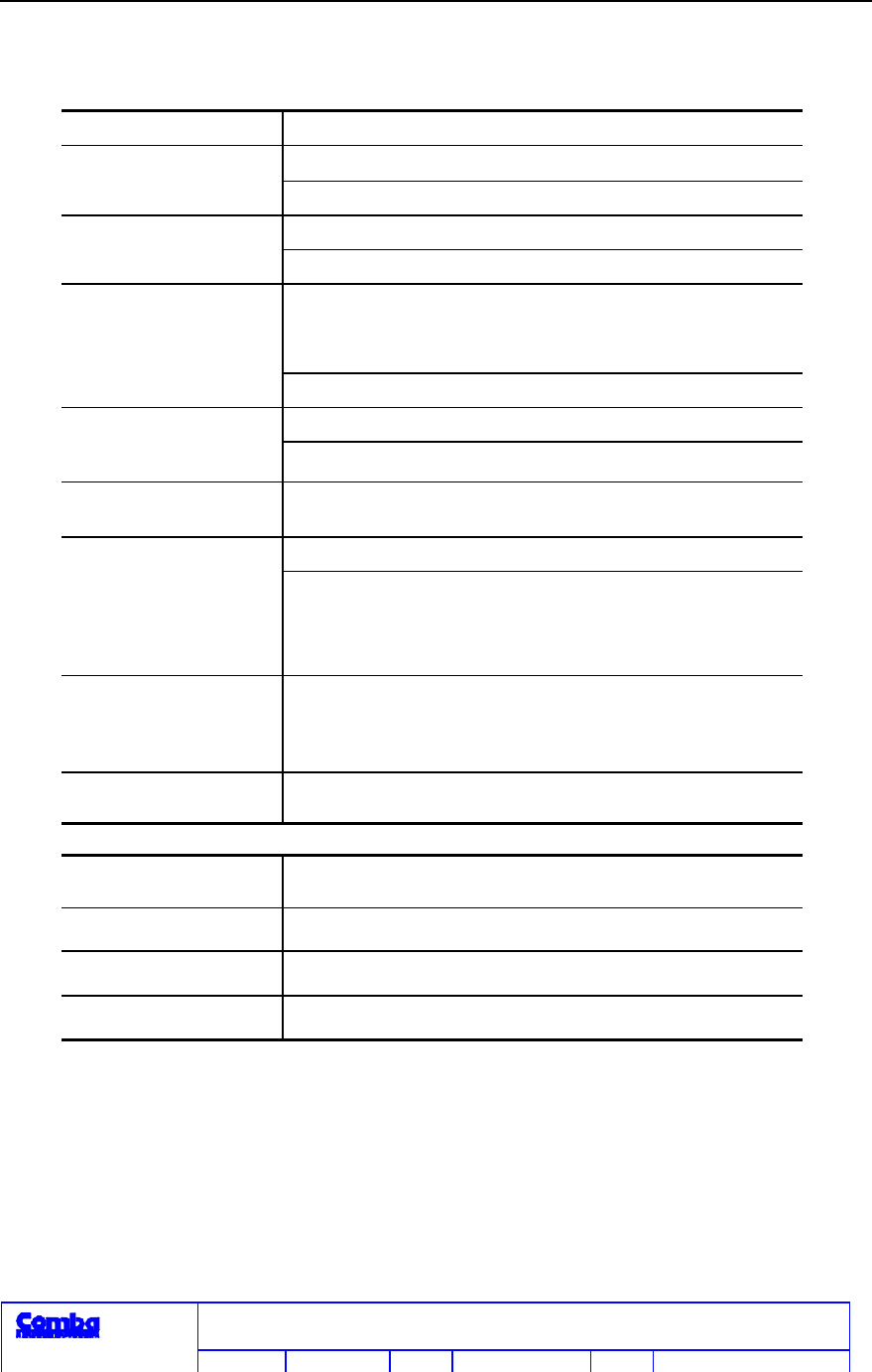
2.4 Specifications
2.4.1 RF Features
Operating system CDMA800/CDMA1900Hz
Uplink824~849/1850~1910MHz
Frequency range Downlink869~894/1930~1960MHz
Uplink15dB (typical)
Gain Downlink15dB (typical)
Uplink30dB(GSM) step 2dB
25dB(1800), step 1dB
Gain adjustable range
DownlinkALC control30dB
Uplink: -25dBm
Maximum input
signal level Downlink+13dBm
Output power 15dBmCDMA800MHz.21dBmCDMA1900MHz
16dBmTDMA1900MHz(typical)
< -13dBm Downlink
Spurious and
intermodulation
output >26dBc Uplink
Noise figure 15dB
Antenna port number 4 per Remote Unit
Flatness within band ±2dB
2.4.2 Optical Features
Transmission
bandwidth 800~2000MHz
Output optical power 0~3dBm
Input IP3 25dBm
Input noise -134dBm/Hz
2.4.3 Operating Conditions
Power supplyAC100~250V
Rated frequency range 50~60Hz
Maximum rated current: 1A
Power supply power lossmaster unit about 35WRemote Unit about30W
Environment temperature: 0~+40°C
Relative humidity: ≤ 85%
RS-5180CDMA800/1900 Dual Band Indoor Fiber Optic
Repeater
Comba Telecom
Edition 2.0 Date 2001-06 13 of 31
3. System Installation
3.1. Installation of Master Unit
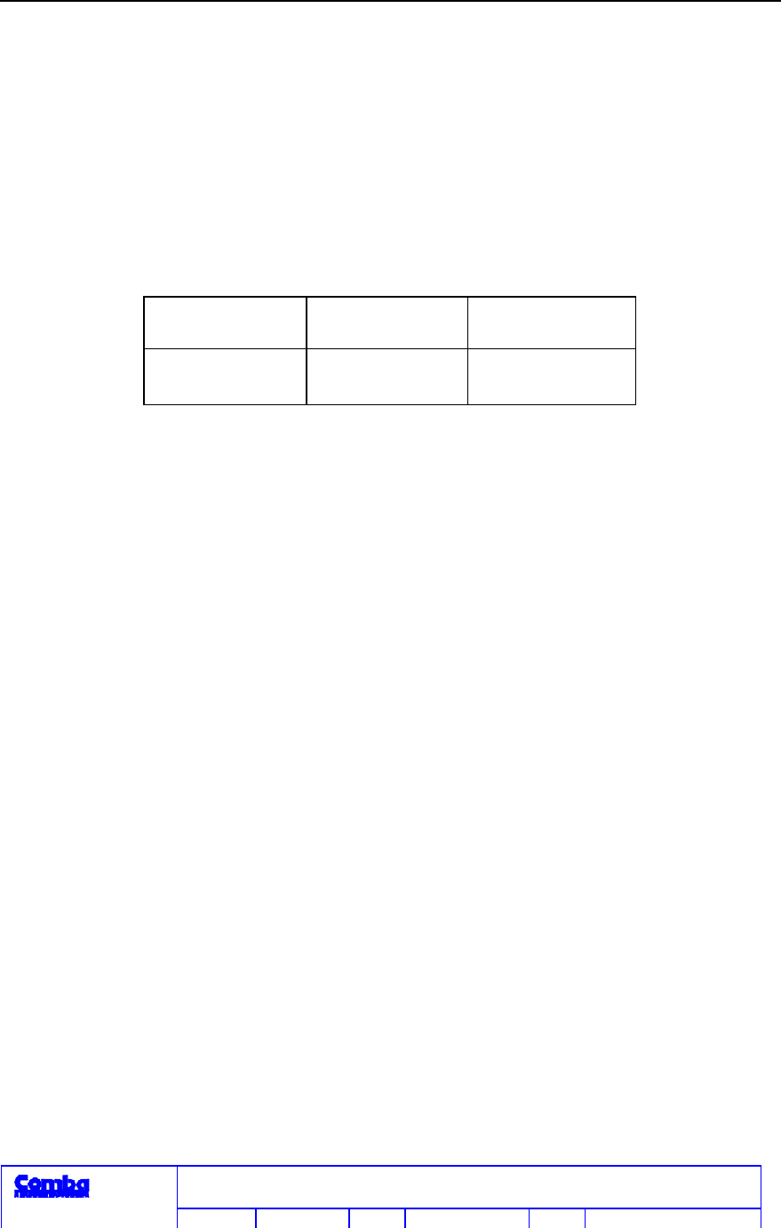
3.1.1 Dimensions
Master unit rack is a standard 19" “portable frame”. Its external
dimensions are as follows:
W H D
564mm 800mm 380mm
Distance between screw fixing holes on the base of the rack are:
Left to right: 524 mm Front to back: 322 mm
3.1.2 Space Requirements
Master unit should be located indoor so that the space for maintenance
and ventilation is ensured. Hence, it is suggested that the back and side of
rack should be at least 80~100cm away from wall or other System.
The place should have good ventilation, with ambient temperature of 0
~40 and relative humidity ≤85%. Direct sunlight on the master unit should be
avoided.
3.1.3 Installation Method
When shipped out of factory, the Master Unit is put into the cabinet19"
6U standard rack while Interface Unit and power supply unit are put
RS-5180CDMA800/1900 Dual Band Indoor Fiber Optic
Repeater
Comba Telecom
Edition 2.0 Date 2001-06 14 of 31
separately in boxes. The “portable rack” for installation of master unit cabinet
(standard 19" portable frame800mm high) is put after disassembled. Therefore,
before install master unit, first assemble portable rack.
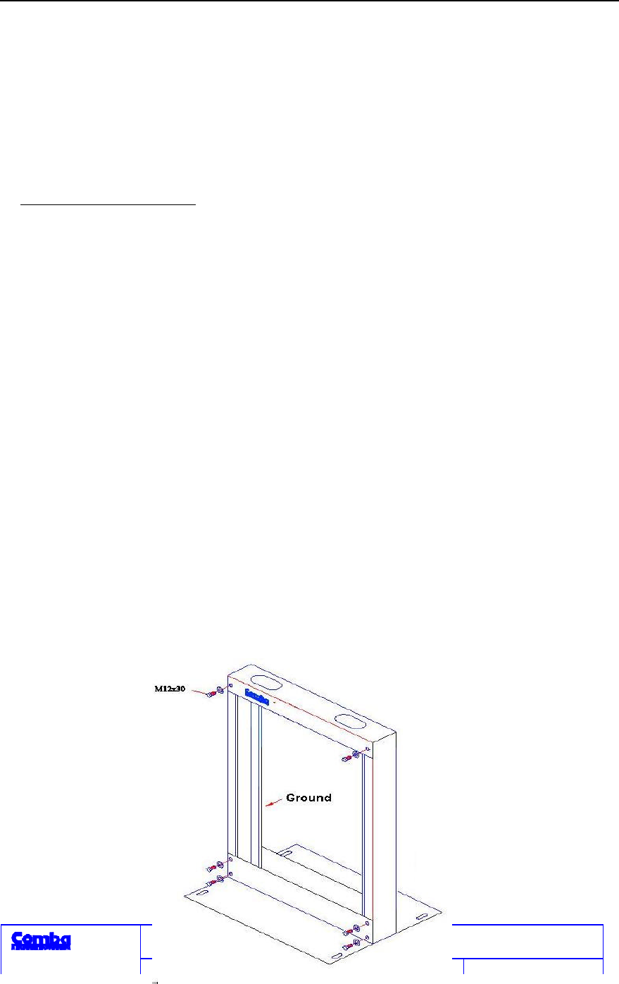
Assembly of Portable Rack
It is quite simple to assemble portable rack as shown in figure 3.1-1. The followings should
be noted:
(1) For the convenience of installation, all the assembly holes on all the
components have sufficient room. Hence, in fixing the last two columns,
ensure to keep the distance between them as long as possible for the
placing of master unit’s cabinet.
(2) Both of the two columns have front and rear sides as well as upper and
lower sides.. There is ground copper slip or many holes on the back side.
The upper end has a hole and the lower end has two holes. The front
side has the trademark of Comba on the upper beam.
(3) All components are steel made and heavy. Pay attention to safety in
assembly and prevent any injury.

RS-5180CDMA800/1900 Dual Band Indoor Fiber Optic
Repeater
Comba Telecom
Edition 2.0 Date 2001-06 15 of 31
Figure3.1-1 Assembly Diagram of Portable Frame
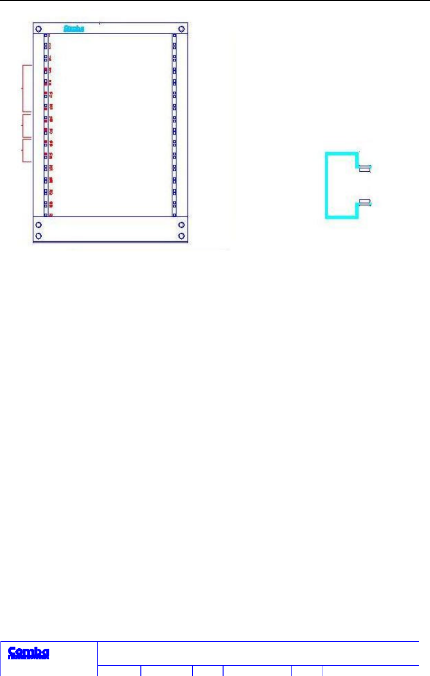
Insertion of M5 Nut Cramp
In order to fix the master unit cabinet, master unit cabinet supports and
tail fiber tray, M5 nut cramps should be pre-inserted onto the two columns of
portable frame. Figure 3.1-2 shows the inserting points-small black square
holes, symmetrical on each column. At the back of the columns (i.e. the side
with ground copper slip or many round holes), 2 nut cramps should also be
inserted into hole 15 and 16 separately since master unit cabinet support should
be fixed at both sides of columns. No nut cramps need to be inserted into other
holes at the rear sides of the columns. Nut cramps are inserted from inside to
outside as shown in figure 3.1-3. After nut cramps are inserted, fix the two
master unit supports onto the two columns with M5 nuts at hole 15 and 16. Nuts
should be tightened at both sides of the columns.
RS-5180CDMA800/1900 Dual Band Indoor Fiber Optic
Repeater
Comba Telecom
Edition 2.0 Date 2001-06 16 of 31
Figure 3.1-2 Figure 3.1-3
RS-5180CDMA800/1900 Dual Band Indoor Fiber Optic
Repeater
Comba Telecom
Edition 2.0 Date 2001-06 17 of 31
Installation of Portable Frame
Well-assembled portable frame can be installed vertically on the ground. Portable frame can
be installed in three ways:
AVertically fixed on the ground;BVertically fixed on the wall support;
CVertically fixed on table.
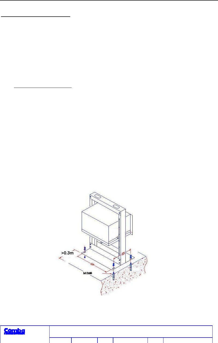
AInstalled on the ground:
(1) Choose the appropriate position indoors. Place the portal frame
vertically on the ground. Mark down the points of four φ13 holes.
(2) Drill 4 holes with electric impact drill and embed four φ10x80mm
expansion screws.
(3) Lift the portal frame. Place it vertically on the ground through the 4
holes. Sleeve on flat gasket and spring washer. Tighten screw nut.
Portal frame is installed well (figure 3.1-4).
Figure 4 Master Unit Installation Schematic Diagram (A)

RS-5180CDMA800/1900 Dual Band Indoor Fiber Optic
Repeater
Comba Telecom
Edition 2.0 Date 2001-06 18 of 31
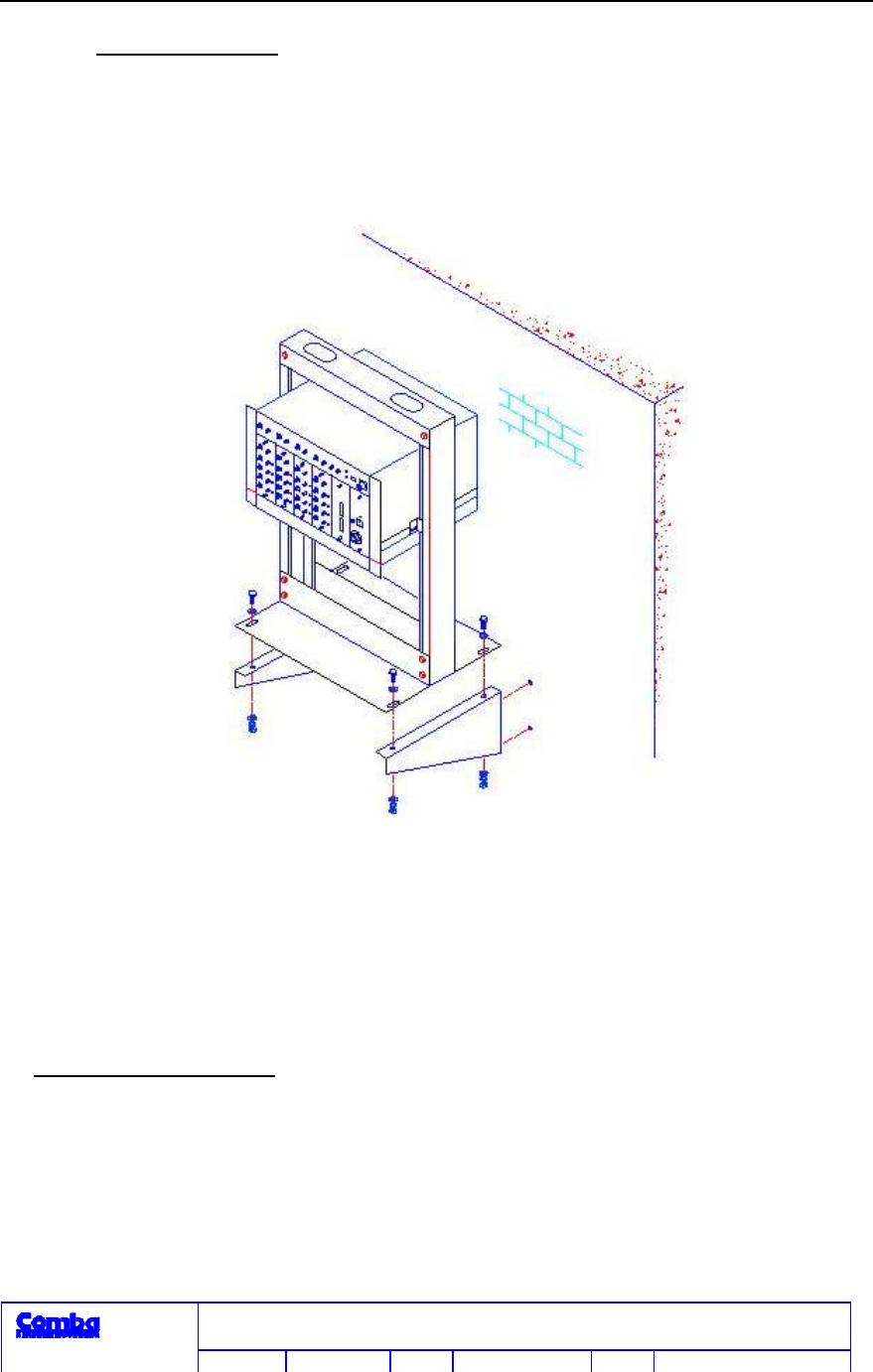
B
Installed on the wall support:
1 For the convenience of marking the fixing holes on wall, first
assemble a baseplate and two wall support as shown in the
Repeating End Installation Schematic Diagram (B) (figure 3.1-5)
to form the baseplate-wall support component. The baseplate
should be removed from the well-assembled portable frame.
Note: Put the portable frame with baseplate removed
horizontally on the ground, not vertically, to ensure safety.
2 Choose an appropriate place on wall. Move the above mentioned
baseplate-wall support component to the place and mark the
positions of 2 φ14 holes at both sides.
3 Drill 4 holes at the four positions with electric impact drill and
embed four φ10x80mm expansion screws.
4 Lift the baseplate-wall support component. Place it stably on
the wall through the 4 holes using flat gasket, spring washer
and nuts.
5 Remove the baseplate of the baseplate-wall support component.
6 Assemble the portable frame as the description about the
assembly of portable frame.
7 Lift the portal frame. Place it stably on the wall support through
the 4 holes on two baseplates and 2 wall supports with
hexagonal M10 screws, flat gasket, spring washer and nuts.
Portal frame is installed well.
RS-5180CDMA800/1900 Dual Band Indoor Fiber Optic
Repeater
Comba Telecom
Edition 2.0 Date 2001-06 19 of 31
C
Installed on table:
The table on which portable frame will be installed on must be quite stable. The
installation procedures are the same as those of installation on the ground.
Figure 3.1-5 Master Unit Installation Schematic Diagram (B)
Installation of Master Unit:
Master unit should be installed as follows:
1 Master Unit is in the master unit cabinet (19" 6U standard
cabinet). Check whether the fixing screws on the panel of
Master Unit has loosened in the transportation. If so, tighten

RS-5180CDMA800/1900 Dual Band Indoor Fiber Optic
Repeater
Comba Telecom
Edition 2.0 Date 2001-06 20 of 31
them.
2 Pla ce the well-assembled master unit into portable frame onto
the master unit cabinet support. Fix the master unit stably on the
portable frame with M5 screws through the fixing holes on the
ears of the master unit cabinet.
3 Put the tail fiber tray (2U sliding cabinet) (used to put tail fiber)
under the master unit cabinet. Also fix it with M5 screws
through the fixing holes on the ears of the cabinet. Fixing holes
are hole 18 and 20.
4 Then connect cables in turn.
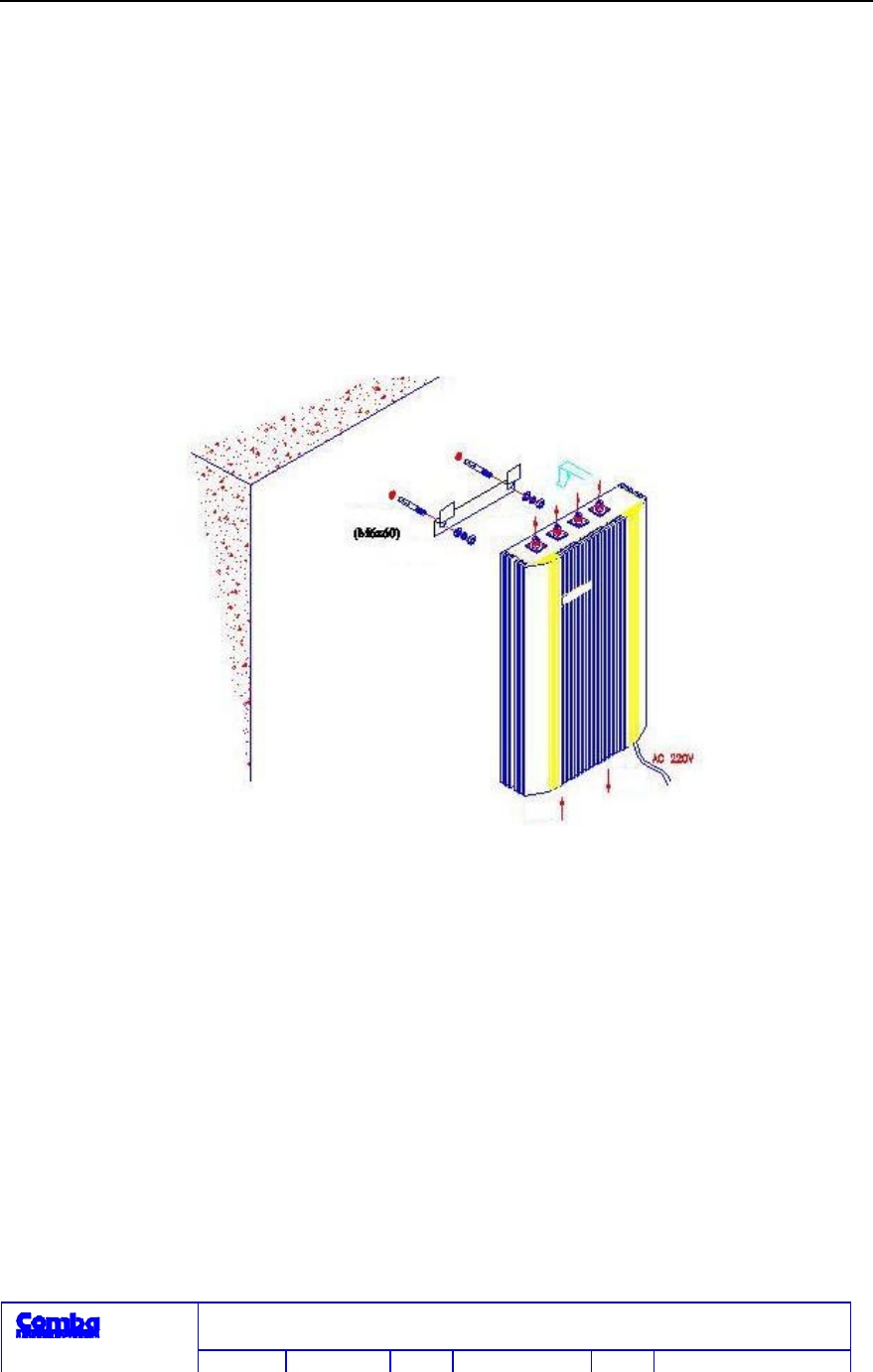
3.2. Installation of Remote Unit
3.2.1 Installation Dimensions
Remote Unit is installed in the way of wall-hanging. External dimensions
are (h×w×d)368mm×220mm×60mm. In installation, drill according to the
distance between the two 8mm holes of the U-shaped hanging hook attached
with the System.
3.2.2 Space Requirements
Remote Unit should be fixed at a suitable position and height on the wall
for the convenience of maintenance. Ambient temperature should be in the
range of 0~40 and relative humidity ≤85%. Avoid direct sunlight.
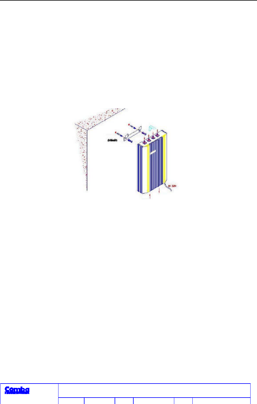
3.2.3 Installation Method
Remote Unit cabinet should be hung on wall as shown in figure 3.2-1.
RS-5180CDMA800/1900 Dual Band Indoor Fiber Optic
Repeater
Comba Telecom
Edition 2.0 Date 2001-06 21 of 31
Figure 3.2-1 RS-5180 Remote Unit Installation Schematic
Diagram
4. System Connection and Debut
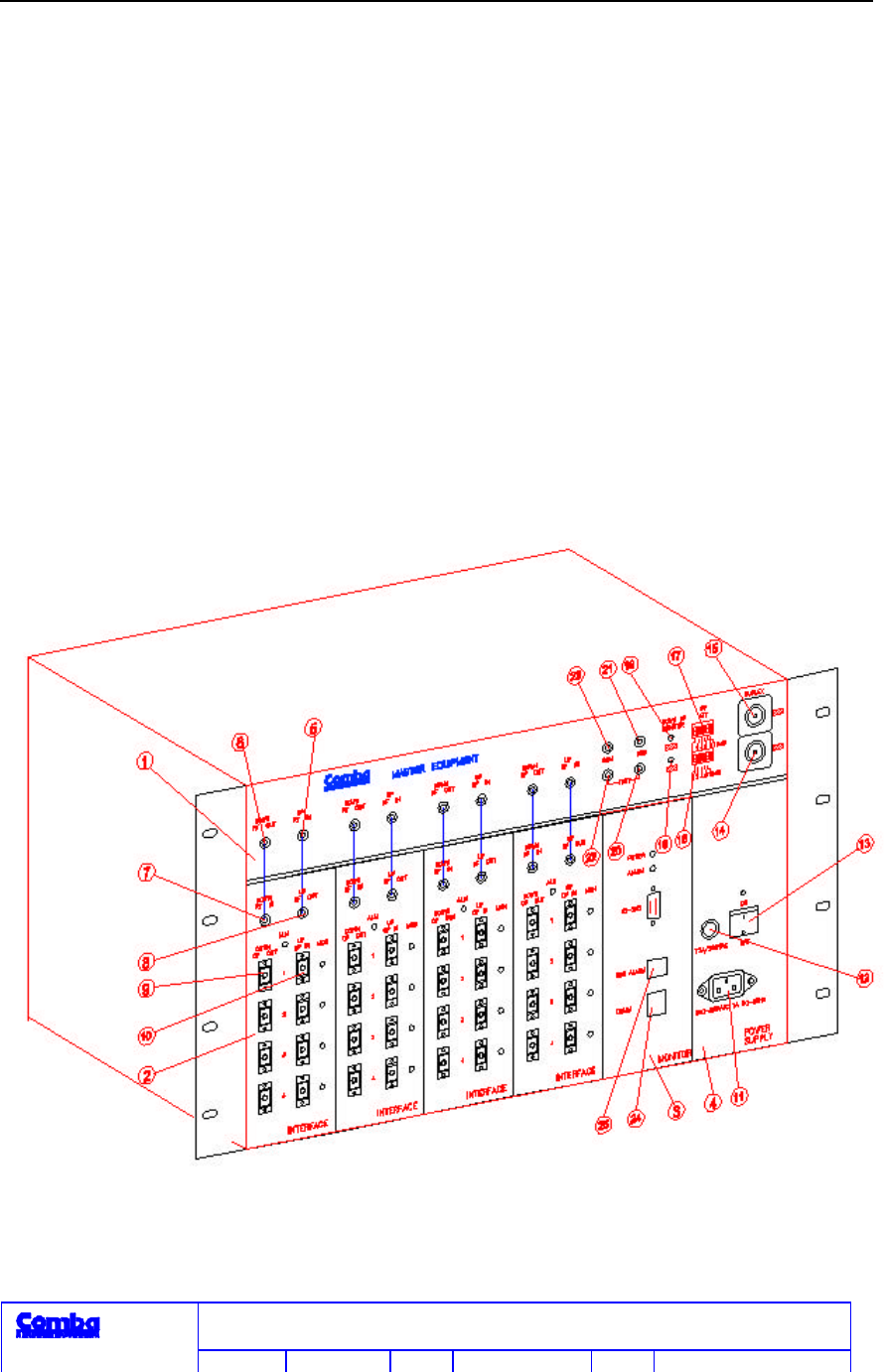
4.1. Master Unit
Refer to master unit panel composition diagram (figure4.1-1).
RS-5180CDMA800/1900 Dual Band Indoor Fiber Optic
Repeater
Comba Telecom
Edition 2.0 Date 2001-06 22 of 31
4.1.1 Connection with RF from BTS
In connecting RF signal from microcellular or BS, first confirm that the
downlink signal from BTS is ≤ 20dBm, otherwise, System may operate
abnormally or circuit may be damaged.
Optimum downlink signal level input into the port connected with GSM
BTS or 1800 BTS (14 and 15 in figure 4.1-1): +5 ~ +20dBm. The maximum
input should not be greater than 20dBm. +10dBm is suggested.
Figure 4-1 Master Unit Panel Composition Diagram

RS-5180CDMA800/1900 Dual Band Indoor Fiber Optic
Repeater
Comba Telecom
Edition 2.0 Date 2001-06 23 of 31
Master Unit
Interface Unit
downlink optical output
port
16 1800M uplink gain
adjustment dip switch
Interface Unit Interface Unit uplink
optic al input port
17 900M uplink gain
adjustment dip switch
Alarm Unit 11 power supply
socket
18 1800M downlink RF
power indicator
power supply
unit 12 fuse seat 19 900M downlink RF
power indicator
Master Unit
uplink RF input port 13 power switch
20 1800M downlink
input check port (coupling
degree 10dB)
Master Unit
downlink RF output
port
14 1800M1800
RF connector
21 1800M uplink output
check port (coupling degree
10dB)
Interface Unit
downlink RF input
port
15 900MGSM
RF connector
22 900M downlink input
check port (coupling degree
10dB)
Interface Unit
uplink RF output port
23 1800M uplink output
check port (coupling degree
10dB)
25 BS external
alarm port
24 communication unit
port
When the two green LED of DOWN RFIN on the front panel of the Master
Unit (figure 4.1-1: 18 and 19) are on, it means that input level of GSM and

RS-5180CDMA800/1900 Dual Band Indoor Fiber Optic
Repeater
Comba Telecom
Edition 2.0 Date 2001-06 24 of 31
1800 >0dBm. When one of them is off, it means that the input level of the
correspondent one is smaller than this normal value.
If only GSM 900MHz or CDMA1900Hz needs to be opened, 50standard load
should be connected with the RF connector not in use. Then, the correspondent
uplink gain adjustment thumb wheel does not function and the correspondent
downlink RF power LED indicator is off.
4.1.2 Uplink Level Adjustment
Uplink level adjustment is a quite important step in the optimization of
system operation. If uplink level is too high, it may have impact on high drop
call rate of BTS (including GSM BTS and 1800 BTS), or even block BTS. If it
is too low, it may reduce the uplink sensitivity at the remote coverage area. In
practice, uplink attenuation should be determined according to the signal
coupling way and coupling degree of BTS. In general, the noise level of signal
input into BTS antenna port should be ≤ -125dBmBW300KHZ. On the panel,
for GSM, UP ATT manual attenuation adjustmentfigure 4.1-1: 16 and 17can
provide the maximum adjustment range of over 30dBm with step of 2dB, and
the correspondent attenuations are 2, 4, 8, 8, and 16dB when DIP code 1, 2, 3,
4, and 5 are at the “ON” position. For 1800, it provides the maximum
adjustment range of over 25dBm with step of 1dB., and the correspondent
attenuations are 1, 2, 4, 8, and 16dB when DIP code 1, 2, 3, 4, and 5 are at
the “ON” position.

RS-5180CDMA800/1900 Dual Band Indoor Fiber Optic
Repeater
Comba Telecom
Edition 2.0 Date 2001-06 25 of 31
4.1.3 RF Connection Between Master Unit and Interface Unit
RF connection between Master Unit (figure 4.1-1: 1) and Interface Unit
(figure 4.1-1: 2 ) should be done with upper and lower parts corresponding with
each other: 6 with 7 and 5 with 8. 4 pairs of fiber-optic connectors (SC
optical flange)-EOWN OPOUT (figure 4.1-1: 9)/UP OPIN (figure 4.1-1: 10) are
on the panel of the Interface Unit. Connect the uplink and downlink optical
fibers from the coverage end with these fiber optic connec\ctors. In connecting
fiber optic connector, never face it toward people’s eyes and skin since laser
beam may hurt people’s eyes and skin.
4.1.4 Check Ports
There are two pairs of RF connectors on the panel of the Master Unit:
One pair is GSM TEST (figure 4.1-1:23-uplink RF output, 22-downlink RF
input) and the other is 1800 TEST (figure 4.1-1:21-uplink RF output,
20-downlink RF input). They are the check ports for GSM and 1800 uplink
and downlink RF signal debug.

RS-5180CDMA800/1900 Dual Band Indoor Fiber Optic
Repeater
Comba Telecom
Edition 2.0 Date 2001-06 26 of 31
4.2. Remote Unit
4.2.1 Connection with RF Cable and Optical Fiber figure 3.2-1: Re mote Unit Installation
Schematic Diagram.
Remote Unit has 4 antenna ports at the top of cabinet for antenna
connection. Connect 50 standard load for any additional port; downlink
fiber-optic input port port (left) and uplink fiber-optic output port port (right)
are at the bottom of cabinet, fiber-optic connector is SC fiber-optic adapter.
4.2.2 Check of Input and Output Optical Power
Measure the receiving power of downlink optical fiber with optical power
meter. The value should be around -5dBm. Actual loss can be taken into
account according to the length of cable connecting master unit and Remote
Unit. Measure the output power of uplink optical fiber with optical power meter
and the value should be around 0-3dBm.

RS-5180CDMA800/1900 Dual Band Indoor Fiber Optic
Repeater
Comba Telecom
Edition 2.0 Date 2001-06 27 of 31
5. User Safety Information
To ensure personal safety and the normal operation of System, please
pay attention to the following:
5.1 System Grounding Well
Housings of both master unit and Remote Unit have protective ground
terminals. In installation, use yellow and green dual color lead to ground well
with building protection ground. Or use ground woven wire.
5.2 Confirming Power Supply
Both master unit and Remote Unit use AC power supply of public
electricity. Rated voltage range is 100~250V. Rated frequency range is 50~60Hz.
The maximum rated current is 1A.
The ground terminal of the 3-core socket used at the installation site
should be connected well with the building protective ground.
5.3 Support With Sufficient Load-bearing Capacity
When System is installed by wall-hanging, the bracket should have
sufficient load-bearing capacity.
5.4 Be Aware of Mechanical Damage
Portable frame is made of steel and quite heavy. Be awasre of personal
safety in installation to avoid any personal hurt. In installation and maintenance,
prevent the scratching of skin by cabinet edge or corner.
5.5 Preventing Laser Radiation
In the installation, test and maintenance of the repeater, avoid the exposure
of eyes or skin to laser radiation.

RS-5180CDMA800/1900 Dual Band Indoor Fiber Optic
Repeater
Comba Telecom
Edition 2.0 Date 2001-06 28 of 31
5.6 Downlink signal level input from BS +20dBm
When connecting RF signal with microcellular or BS, be sure that the
downlink signal level from GSM BTS and 1800 BTS be less than or equal to
+20dBm (+10dBm is suggested), or the System may work abnormally
or even the circuit may be destroyed.

RS-5180CDMA800/1900 Dual Band Indoor Fiber Optic
Repeater
Comba Telecom
Edition 2.0 Date 2001-06 29 of 31
6. Service Manual
6.1 Our Promises
6.1.1 Quality Guarantee
For any quality problems of the System provided to customers, the sales contract signed by both
seller and buyer should be followed.
6.1.2 Technical Training
Our company can provide training for installation and maintenance staff. The relevant terms and
conditions should be laid down in the sales contract signed by seller and buyer.
6.1.3 Engineering Installation
Our company provides engineering installation service for customers. The relevant terms and
conditions should be laid down in the sales contract signed by both seller and buyer.

RS-5180CDMA800/1900 Dual Band Indoor Fiber Optic
Repeater
Comba Telecom
Edition 2.0 Date 2001-06 30 of 31
6.2 Contact Details
6.2.1 Company Name
Comba Telecom Systems (Guangzhou) Co., Ltd.
6.2.2 Company Address and Post Code
Address: No. 6, Jinbi Road, Guangzhou Economics and Technology Development District,
Guangdong, China
Post Code: 510730
6.2.3 Contact Department
Marketing Department
Tel.: (8620) 82225788 Fax: (8620) 82226121
http://www.comba-telecom.com
E-mail: comba@public.guangzhou.gd.cn