Comba Telecom COMFLEX-6800 ComFlex Series Distributed Antenna System User Manual
Comba Telecom Ltd. ComFlex Series Distributed Antenna System
UserManual.wiki
>
Comba Telecom
>
COMFLEX 6800 User Manual
User Manual
Navigation menu
Upload a User Manual
Namespaces
Wiki Guide
HTML
PDF
Info
Views
User Manual
Discussion / Help
Navigation
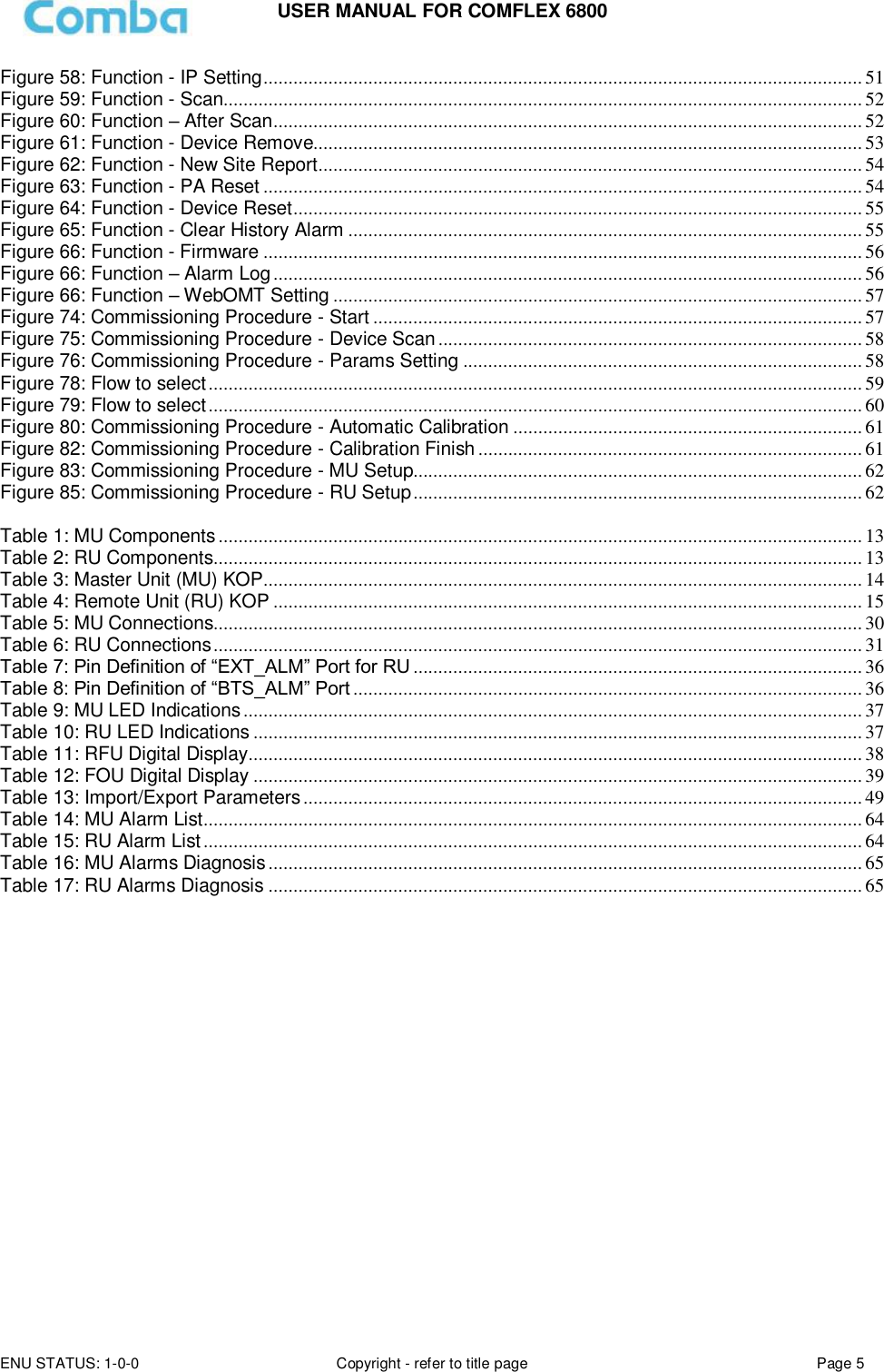
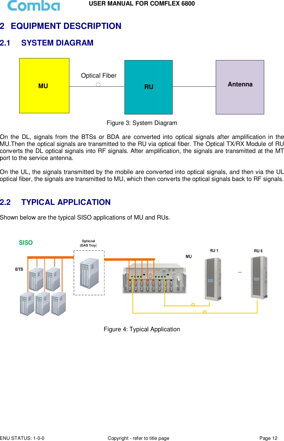
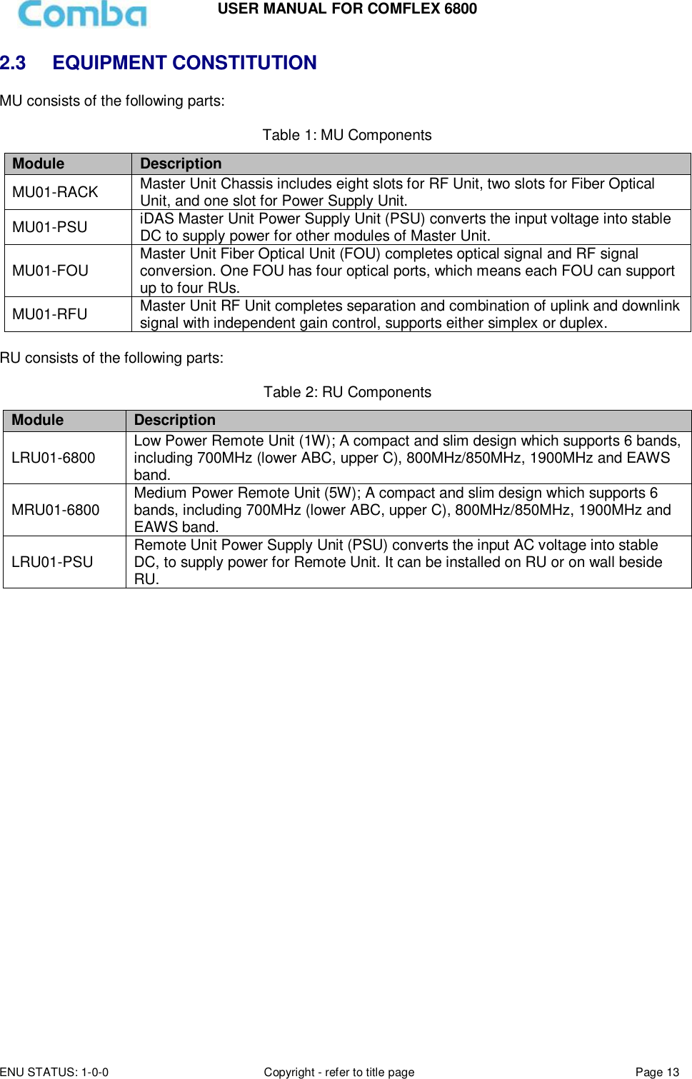
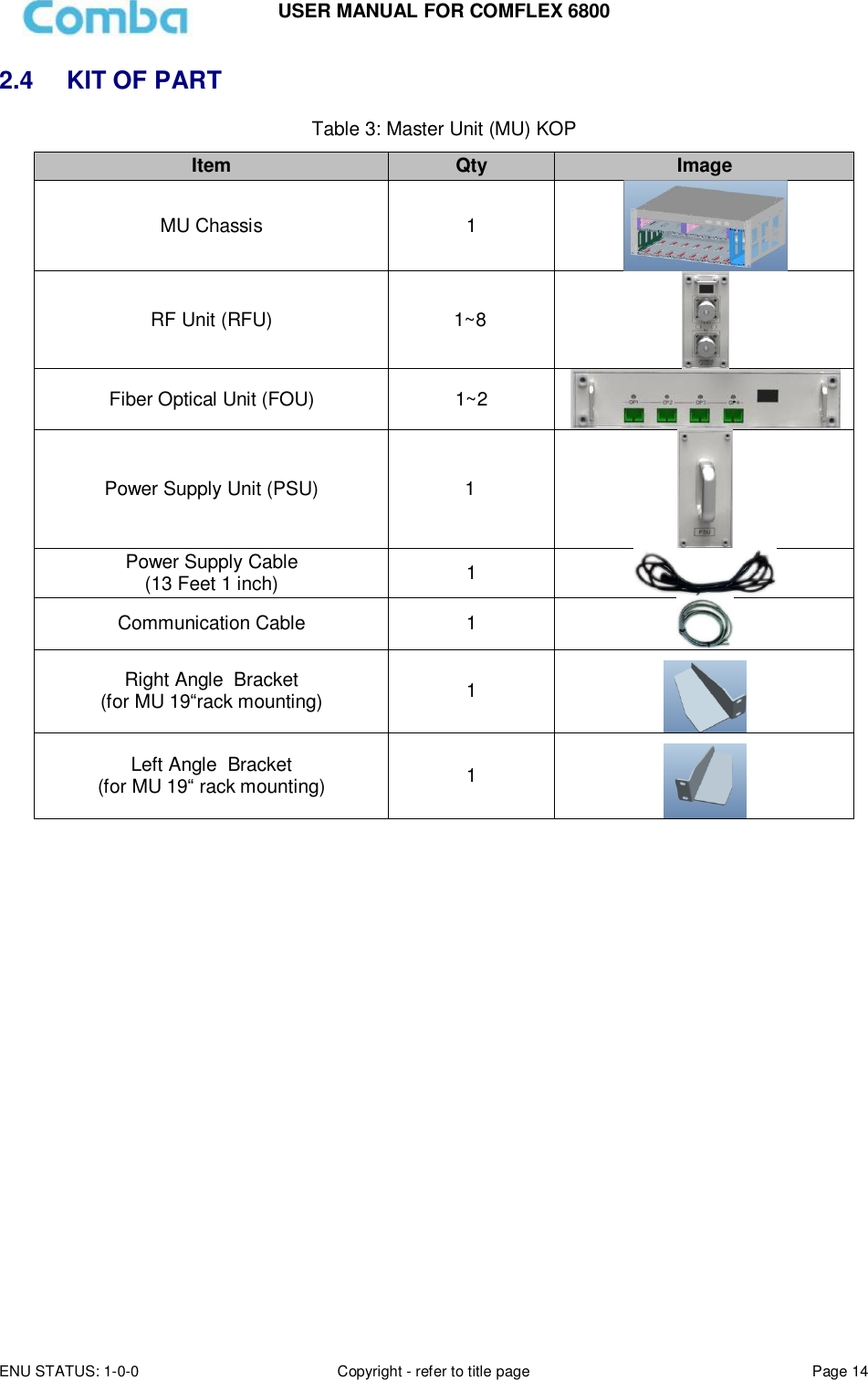
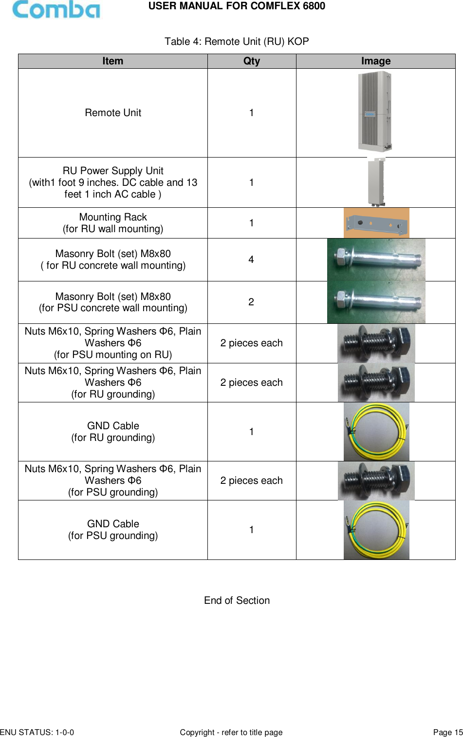
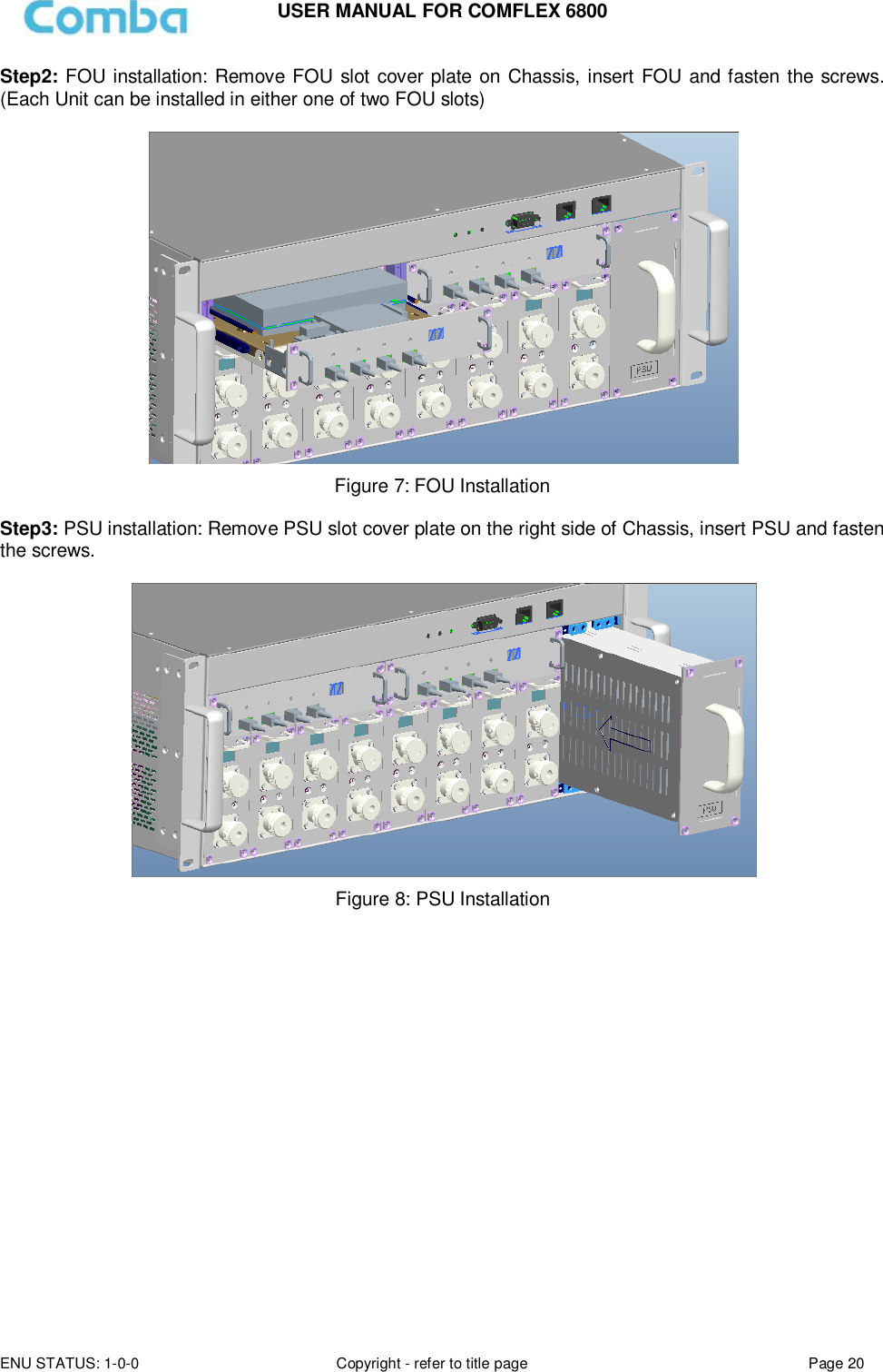
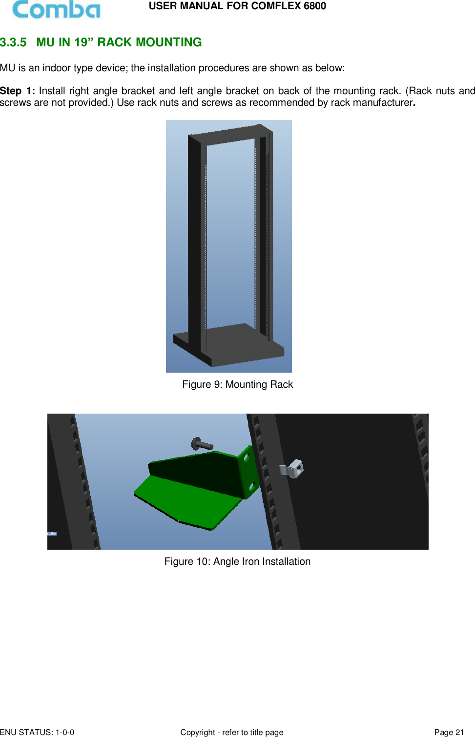
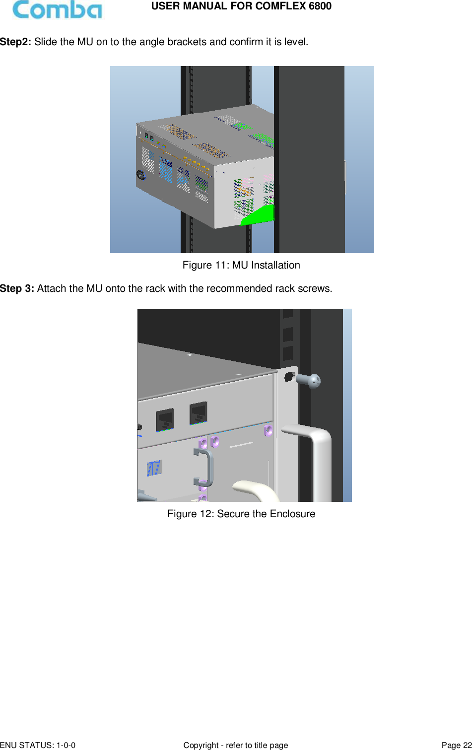
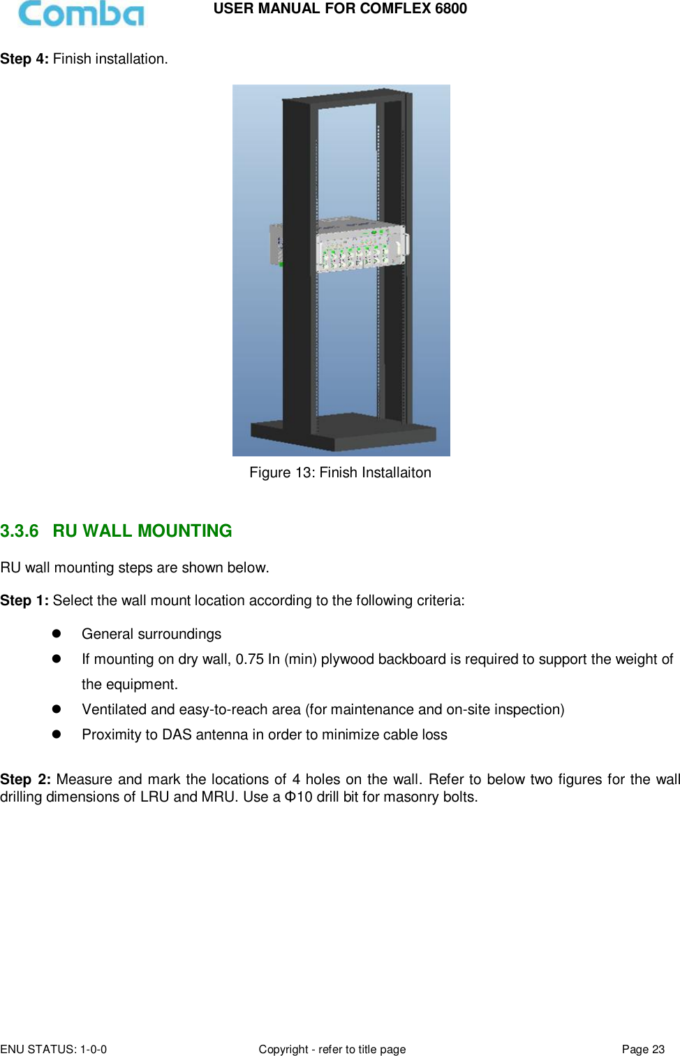
![USER MANUAL FOR COMFLEX 6800 ENU STATUS: 1-0-0 Copyright - refer to title page Page 3 0.1 CONTENTS Section Page 0.1 CONTENTS ................................................................................................................................................ 3 0.2 INDEX TO FIGURES AND TABLES ................................................................................................................. 4 0.3 HISTORY ................................................................................................................................................... 6 0.4 GLOSSARY OF TERMS ................................................................................................................................ 7 0.5 SAFETY NOTICES AND ADMONISHMENTS .................................................................................................. 8 1 GENERAL INFORMATION ............................................................................................................................ 10 2 EQUIPMENT DESCRIPTION .......................................................................................................................... 12 2.1 SYSTEM DIAGRAM .................................................................................................................................. 12 2.2 TYPICAL APPLICATION ............................................................................................................................. 12 2.3 EQUIPMENT CONSTITUTION ................................................................................................................... 13 2.4 KIT OF PART ............................................................................................................................................ 14 3 INSTALLATION ............................................................................................................................................ 16 3.1 WARNINGS AND ALERTS ......................................................................................................................... 16 3.2 SITE PLANNING CONSIDERATIONS ........................................................................................................... 17 3.3 INSTALLATION PROCEDURES ................................................................................................................... 18 3.4 EQUIPMENT CONNECTORS ..................................................................................................................... 28 3.5 EQUIPMENT CONNECTION ....................................................................................................................... 32 4 COMMISSIONING ....................................................................................................................................... 37 4.1 PRE-COMMISSIONING TASKS .................................................................................................................. 37 4.2 LED INDICATORS ..................................................................................................................................... 37 4.3 DIGITAL DISPLAY INDICATORS ................................................................................................................. 38 4.3.1 DIGITAL DISPLAY ON RFU .................................................................................................................... 38 4.3.2 DIGITAL DISPLAY ON FOU.................................................................................................................... 38 5 WEB GUI ..................................................................................................................................................... 40 5.1 WEB GUI CONNECTION ............................................................................................................................... 40 5.2 WEB GUI INTRODUCTION ........................................................................................................................... 41 5.2.1 [DEVICES] ............................................................................................................................................... 42 5.2.2 [FUNCTION]............................................................................................................................................ 47 5.2.3 [AUTO SETUP] ........................................................................................................................................ 47 5.1.1 [FUNCTION] .................................................................................................................................... 48 5.3 COMMISSIONING PROCEDURE ................................................................................................................... 57 6 ALARMS AND TROUBLESHOOTING ............................................................................................................. 64 6.1 ALARMS ...................................................................................................................................................... 64 6.2 TROUBLESHOOTING ................................................................................................................................... 65 7 APPENDICES ............................................................................................................................................... 66 7.1 APPENDIX A: TOOLS FOR INSTALLATION AND MAINTENANCE .................................................................... 66 7.2 APPENDIX B: RMA (RETURN MATERIAL AUTHORIZATION) ......................................................................... 67](https://usermanual.wiki/Comba-Telecom/COMFLEX-6800/User-Guide-3723167-Page-3.png)
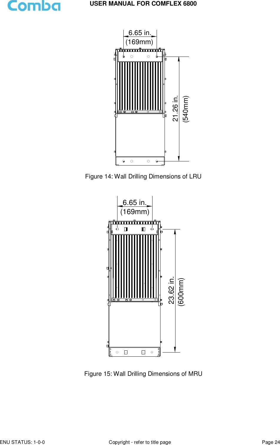
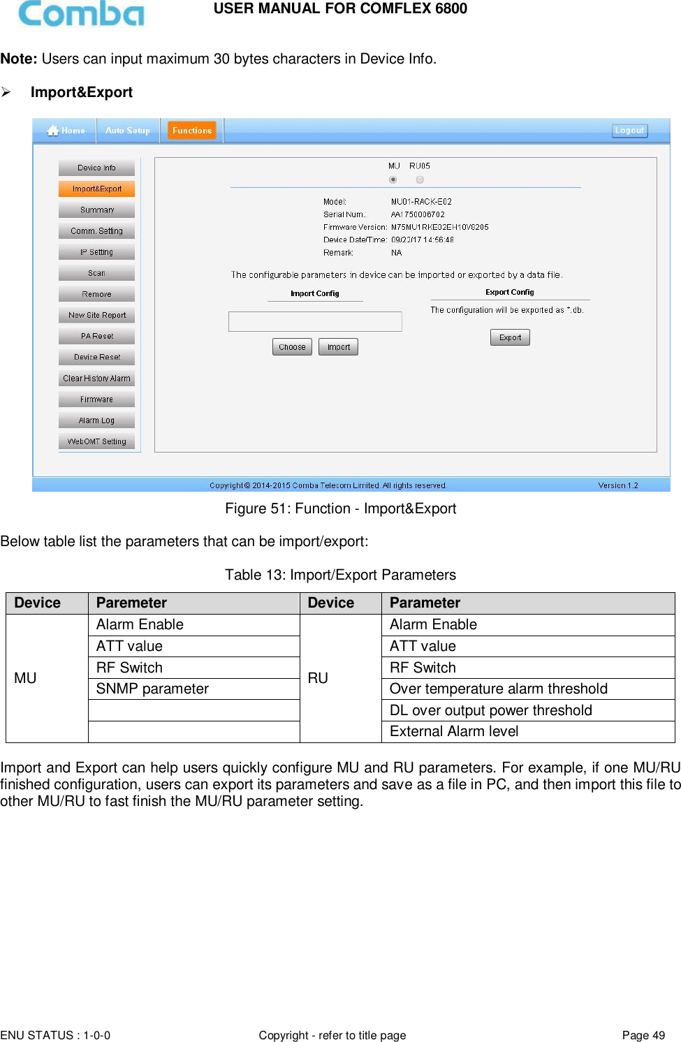
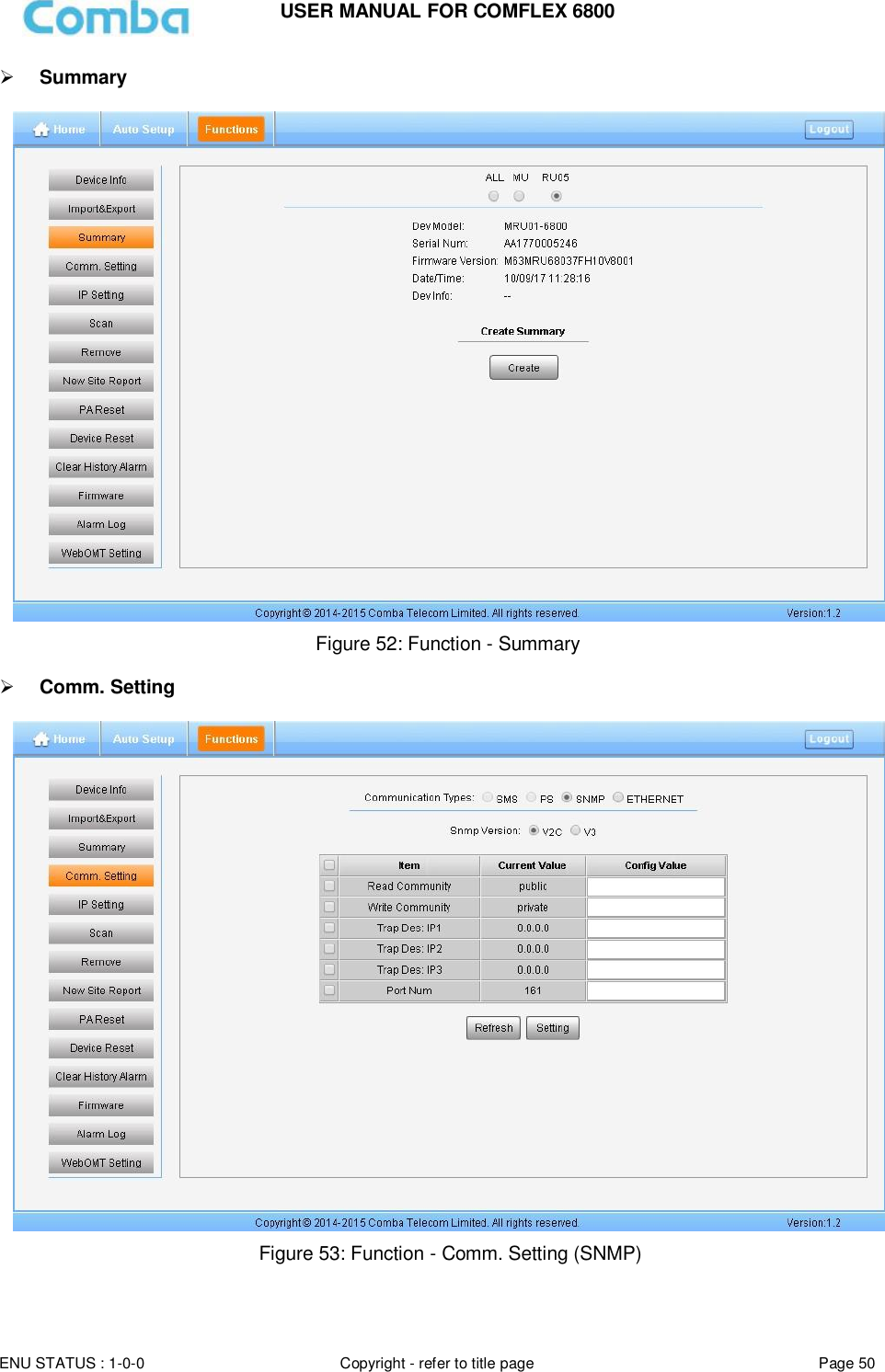
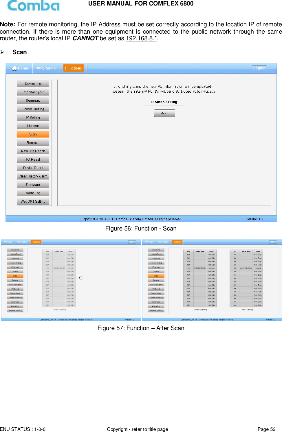
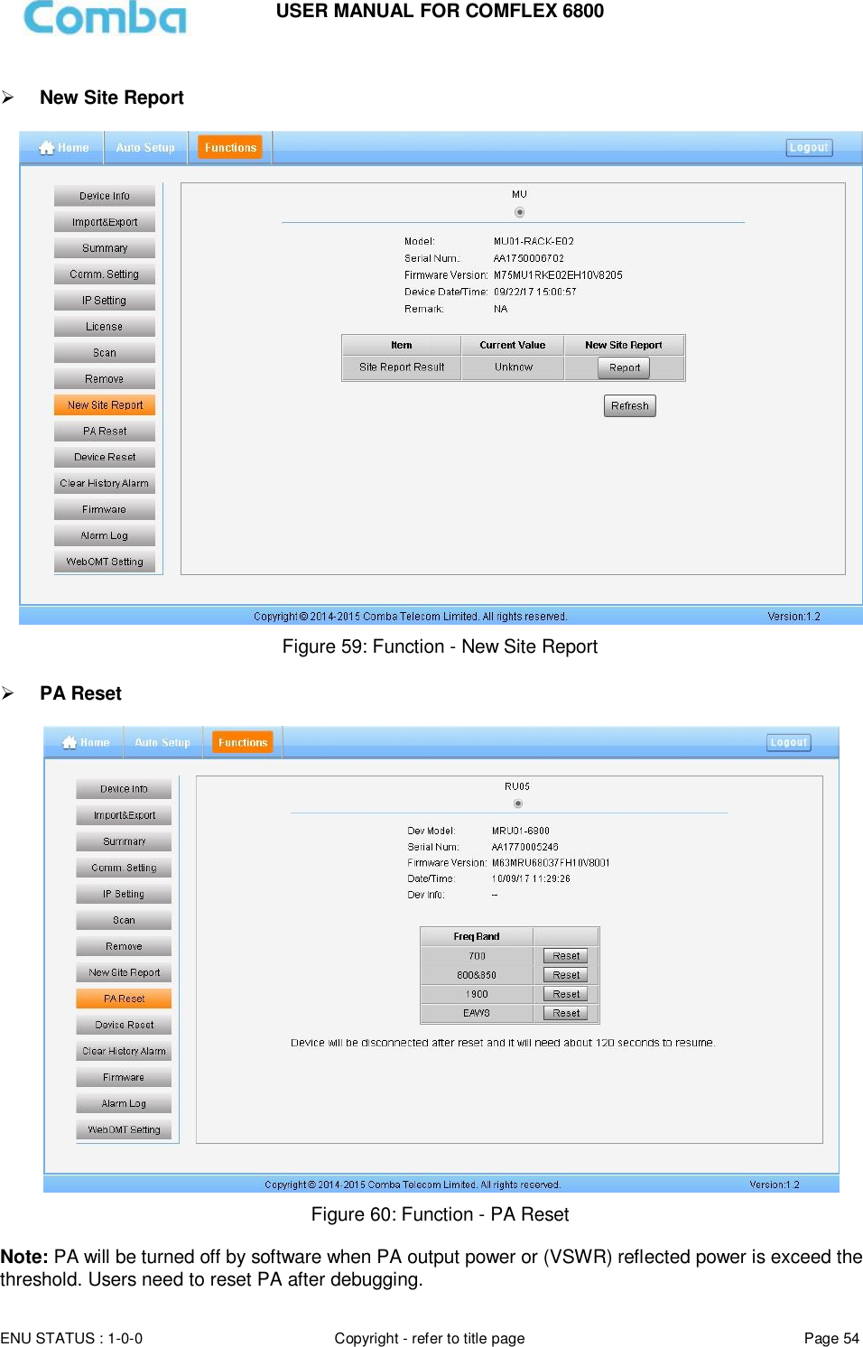
![USER MANUAL FOR COMFLEX 6800 ENU STATUS: 1-0-0 Copyright - refer to title page Page 4 0.2 INDEX TO FIGURES AND TABLES Figure 1: Master Unit (MU) ............................................................................................................................... 10 Figure 2: Remote Unit (RU) .............................................................................................................................. 11 Figure 3: System Diagram ................................................................................................................................ 12 Figure 4: Typical Application ............................................................................................................................. 12 Figure 5: ComFlex Master Unit ......................................................................................................................... 19 Figure 6: RF Unit Installation ............................................................................................................................ 19 Figure 7: FOU Installation ................................................................................................................................. 20 Figure 8: PSU Installation ................................................................................................................................. 20 Figure 9: Mounting Rack ................................................................................................................................... 21 Figure 10: Angle Iron Installation ...................................................................................................................... 21 Figure 11: MU Installation ................................................................................................................................. 22 Figure 12: Secure the Enclosure ...................................................................................................................... 22 Figure 13: Finish Installaiton ............................................................................................................................. 23 Figure 14: Wall Drilling Dimensions of LRU..................................................................................................... 24 Figure 15: Wall Drilling Dimensions of MRU ................................................................................................... 24 Figure 16: Install Mounting Rack on the Wall ................................................................................................. 25 Figure 17: Hang RU onto the Mounting Rack.................................................................................................. 25 Figure 18: Tighten the Screws at the Bottom of RU ....................................................................................... 26 Figure 19: Tighten Two Hexagon Screws ........................................................................................................ 26 Figure 20: Install PSU on RU ............................................................................................................................ 27 Figure 21: Wall Drilling Dimensions of PSU .................................................................................................... 27 Figure 22: Install PSU on the Wall ................................................................................................................... 28 Figure 23: MU Front Panel Connectors ........................................................................................................... 28 Figure 24: MU Rear Panel Connectors ............................................................................................................ 29 Figure 25: 4.3-10 Female Dimension ............................................................................................................... 30 Figure 26: RU Connectors ................................................................................................................................ 31 Figure 27: MU Grounding (MU Rear Panel) .................................................................................................... 32 Figure 28: RU Grounding .................................................................................................................................. 33 Figure 29: Fiber Optical and RF Port Connection ........................................................................................... 34 Figure 30: MU Power Connection (Rear Panel) .............................................................................................. 34 Figure 31: RU Fiber Optical and RF Port Connection ................................................................................... 35 Figure 32: PSU Power Port Connection .......................................................................................................... 35 Figure 33: Pins Allocation for “EXT_ALM” Port for RU .................................................................................. 36 Figure 34: Pins Allocation for “BTS_ALM” Port ............................................................................................... 36 Figure 35: RFU Digital Display ......................................................................................................................... 38 Figure 36: Optical Port No. and Digital Display ............................................................................................... 38 Figure 37: PC IP Address Setting .................................................................................................................... 40 Figure 38: Input IP Address .............................................................................................................................. 40 Figure 39: Input User Name and Password .................................................................................................... 41 Figure 40: Web GUI Main Screen .................................................................................................................... 41 Figure 41: [Devices] Sceen ............................................................................................................................... 42 Figure 42: MU Device - Monitoring Unit ........................................................................................................... 43 Figure 43: MU Device - Optical Unit ................................................................................................................. 43 Figure 44: MU Device - RF Unit ....................................................................................................................... 44 Figure 45: RU Device ........................................................................................................................................ 45 Figure 46: RU Device – 700.............................................................................................................................. 46 Figure 47: RU Device – External Alarm ........................................................................................................... 46 Figure 48: [Auto Setup] Screen ........................................................................................................................ 47 Figure 51: [Auto Setup] Screen ........................................................................................................................ 48 Figure 53: Function - Device Info. .................................................................................................................... 48 Figure 54: Function - Import&Export ................................................................................................................ 49 Figure 55: Function - Summary ........................................................................................................................ 50 Figure 56: Function - Comm. Setting (SNMP) ................................................................................................. 50 Figure 57: Function - Comm. Setting (UDP) .................................................................................................... 51](https://usermanual.wiki/Comba-Telecom/COMFLEX-6800/User-Guide-3723167-Page-4.png)
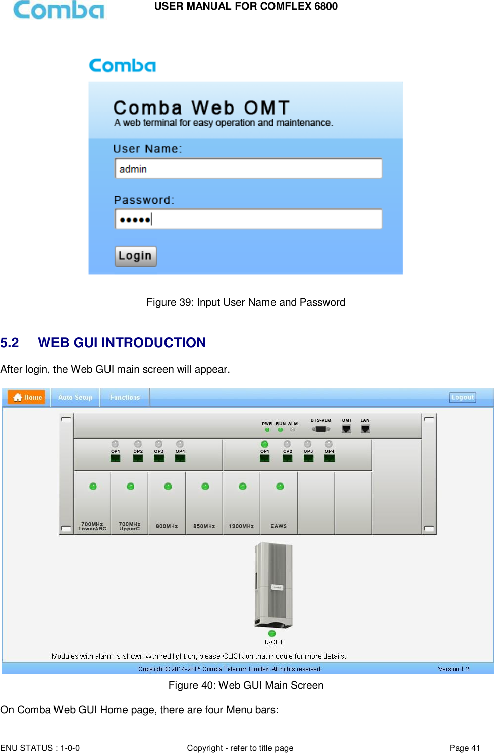
![ENU STATUS : 1-0-0 Copyright - refer to title page Page 40 Page 4040 5 WEB GUI ComFlex can be monitored and controlled by WEB GUI, follow below contents to achive system parameter setting and commissioning. 5.1 WEB GUI CONNECTION Step 1: Connect MU OMT port to PC RJ45 port with the supplied Ethernet cable to set up a physical connection. Step 2: Go to laptop Control Panel\Network and Internet\Local Area Connection. Right click it and click Properties. Then follow the steps shown in figure below. Figure 37: PC IP Address Setting Step 3: Open browser (browser IE7.0, IE8.0, Chrome or Firefox, suggest disply resolution is 1024×768), input Web GUI IP address: 192.168.8.101, click [Enter]. Figure 38: Input IP Address Step 2: Input User Name: admin; Password (default password: admin). Click [Log in].](https://usermanual.wiki/Comba-Telecom/COMFLEX-6800/User-Guide-3723167-Page-40.png)
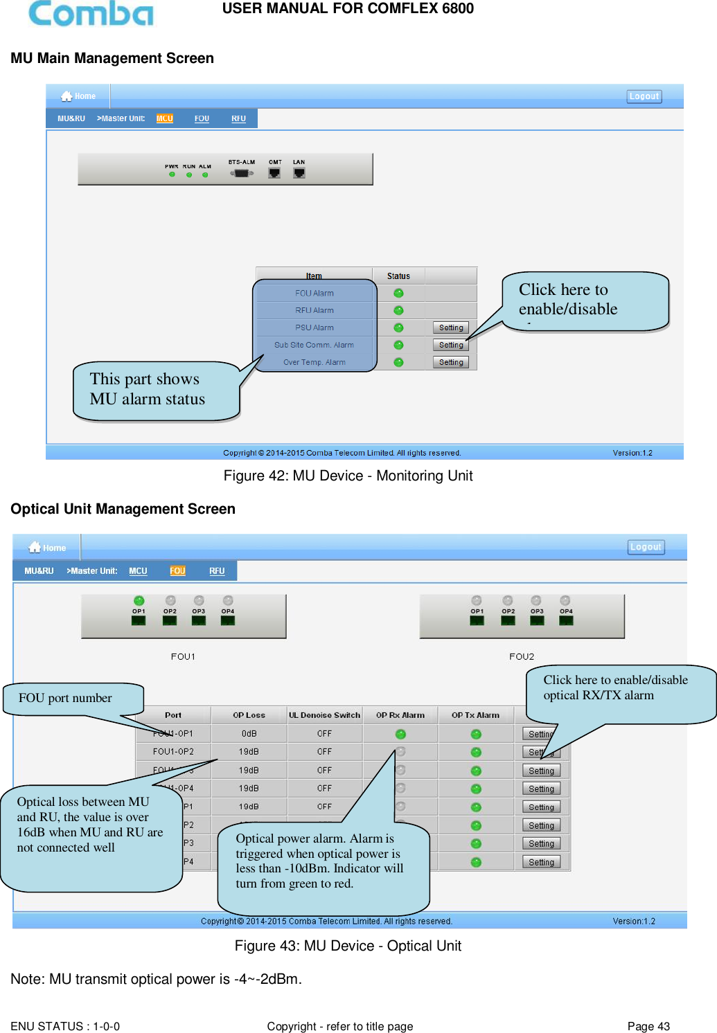
![USER MANUAL FOR COMFLEX 6800 ENU STATUS : 1-0-0 Copyright - refer to title page Page 42 [Devices], Commissioning], [Firmware] and [Management]. 5.2.1 [DEVICES] The [Devices] page shows the actual connection diagram of MU and RU. Figure 41: [Devices] Sceen Click here for MU main management page Click here for RU main management page Click here for RFU main management page Click here for FOU main management page](https://usermanual.wiki/Comba-Telecom/COMFLEX-6800/User-Guide-3723167-Page-42.png)
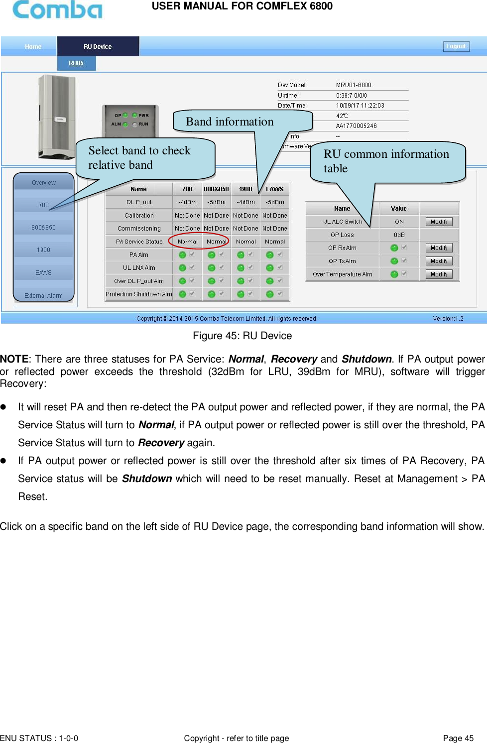
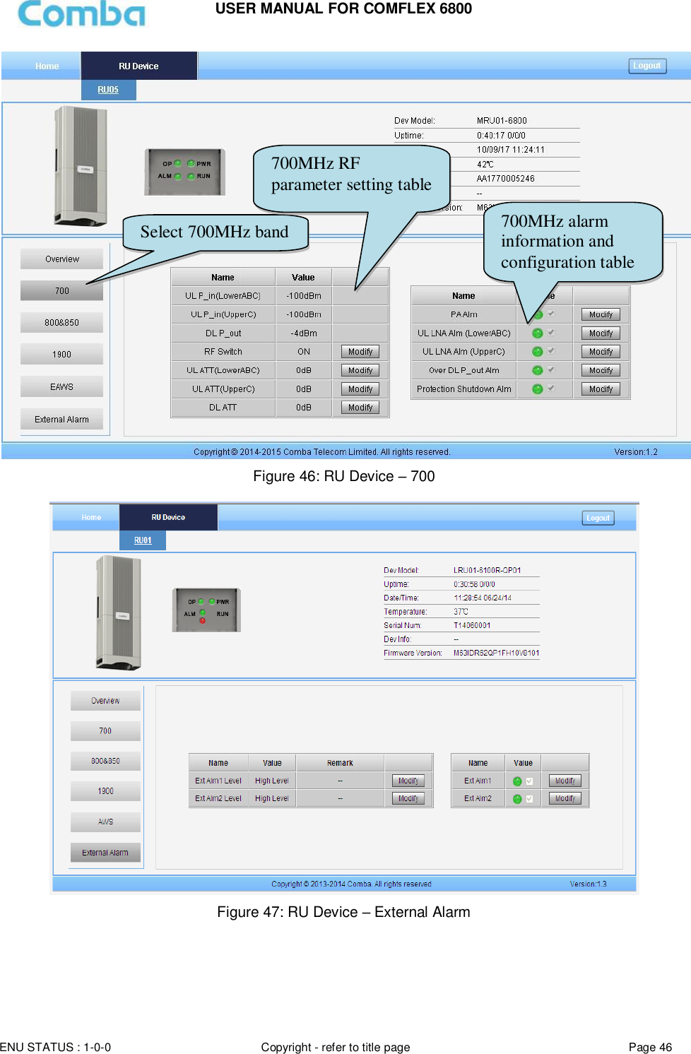
![USER MANUAL FOR COMFLEX 6800 ENU STATUS : 1-0-0 Copyright - refer to title page Page 44 RF Unit Management Screen Figure 44: MU Device - RF Unit Remote Unit Management Screen Click RU photo, users can visit RU directly. Make sure two steps are done before visit RU: RU and MU are connected by optical fiber. RU device scanning is done. Note: Go to [Commissioning] page or [Management] page for device scanning. Slot number Band and Remark information RF parameter Commissioning status Downlink input power overdrive alarm Click here to ON/OFF RF switch and modify attenuator](https://usermanual.wiki/Comba-Telecom/COMFLEX-6800/User-Guide-3723167-Page-44.png)
![USER MANUAL FOR COMFLEX 6800 ENU STATUS : 1-0-0 Copyright - refer to title page Page 47 5.2.2 [FUNCTION] A work flow of the commissioning process is shown on [Auto Setup] page. Click the [Start] button, the software will guide you through the commissioning step by step. For details, please refer to chapter 5.3. Figure 48: [Auto Setup] Screen 5.2.3 [AUTO SETUP] A work flow of the commissioning process is shown on [Auto Setup] page. Click the [Start] button, the software will guide you through the commissioning step by step. For details, please refer to chapter 5.3.](https://usermanual.wiki/Comba-Telecom/COMFLEX-6800/User-Guide-3723167-Page-47.png)
![USER MANUAL FOR COMFLEX 6800 ENU STATUS : 1-0-0 Copyright - refer to title page Page 48 Figure 49: [Auto Setup] Screen 5.1.1 [FUNCTION] Other parameters can be configured on [Function] page. There are fifteen function bars list in the left side of the [Mangement] page. Below figures are the introduction of each function bar. Devic Info. Figure 50: Function - Device Info.](https://usermanual.wiki/Comba-Telecom/COMFLEX-6800/User-Guide-3723167-Page-48.png)

![USER MANUAL FOR COMFLEX 6800 ENU STATUS : 1-0-0 Copyright - refer to title page Page 53 Device Remove Figure 58: Function - Device Remove Note: If the RU has been scanned and identified by MU, to remove the RU from the system,users must remove this RU on this [Remove] page, otherwise, RU will still be shown on the Home page and will trigger optical alarm.](https://usermanual.wiki/Comba-Telecom/COMFLEX-6800/User-Guide-3723167-Page-53.png)
![USER MANUAL FOR COMFLEX 6800 ENU STATUS : 1-0-0 Copyright - refer to title page Page 56 Firmware There are three functions on the [Firmware] bar: [Monitoring Upgrade], [Swap] and [Module Upgrade]. [Monitoring Upgrade] is used to upgrade software. [Swap] is to replace current firmware version to the previous one. [Module Upgrade] is used to upgrade module software. Figure 63: Function - Firmware Alarm Log Figure 64: Function – Alarm Log Master unit software upgrade Master Unit software swap Slaver Unit software upgrade](https://usermanual.wiki/Comba-Telecom/COMFLEX-6800/User-Guide-3723167-Page-56.png)
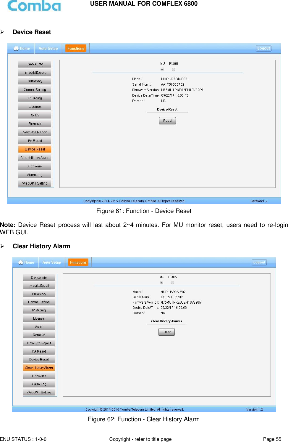
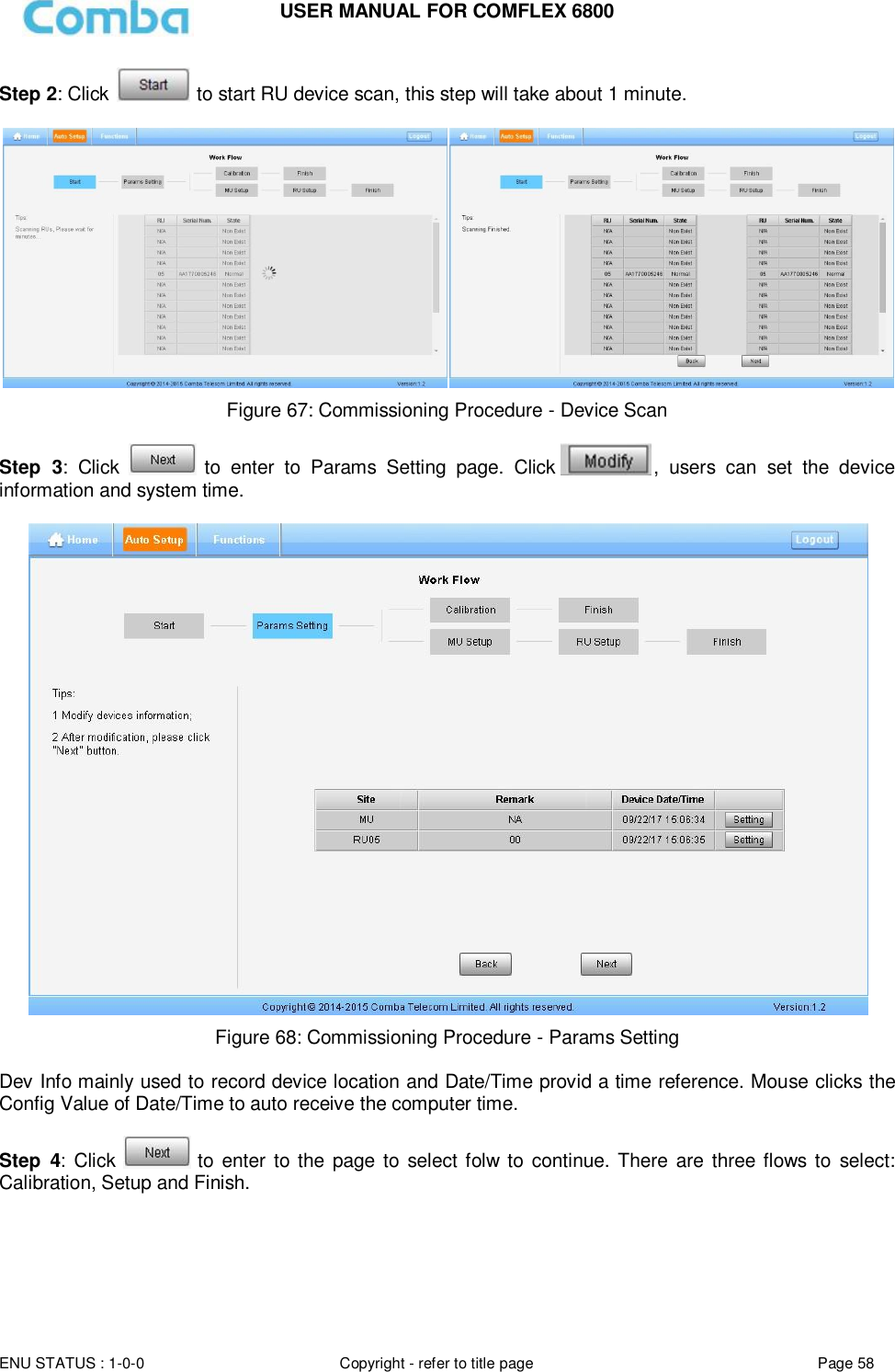
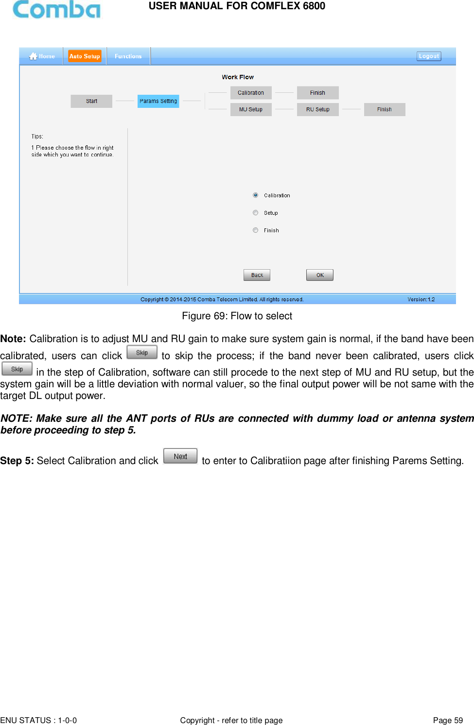
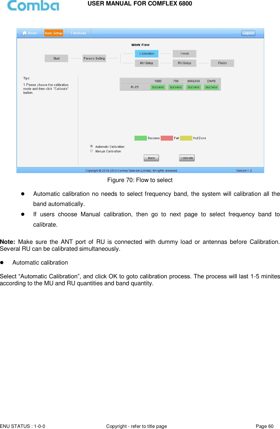
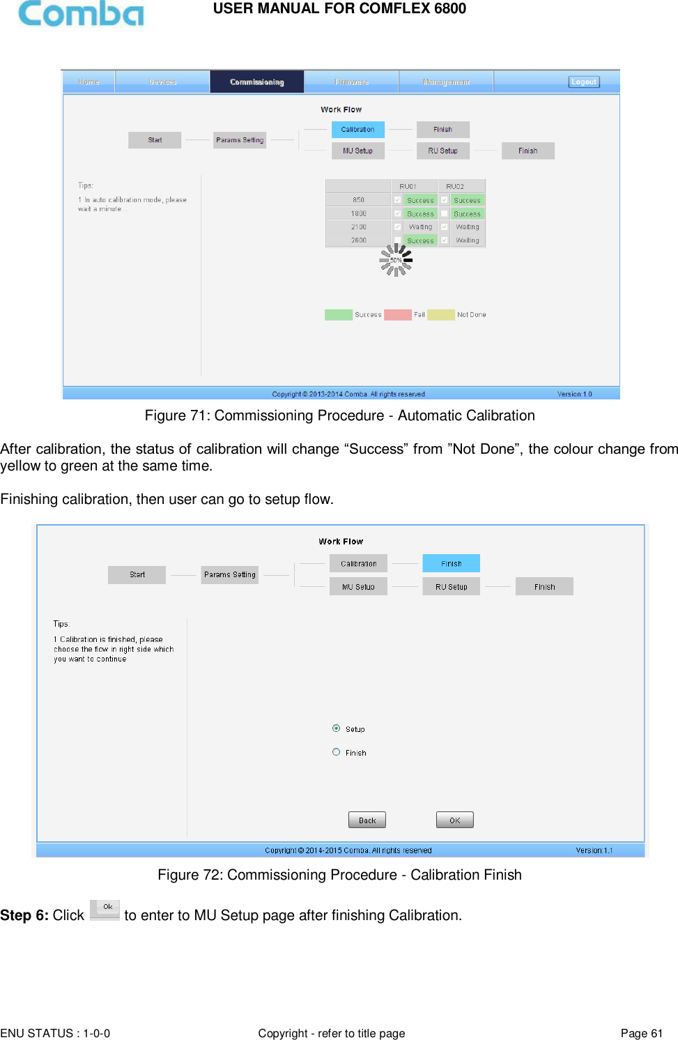
![USER MANUAL FOR COMFLEX 6800 ENU STATUS : 1-0-0 Copyright - refer to title page Page 57 WebOMT Setting Figure 65: Function – WebOMT Setting 5.3 COMMISSIONING PROCEDURE To complete the installation and commissioning, users need to follow the steps below. Step 1: Click Menu bar [Auto Setup] on home page, a work flow will show up. Figure 66: Commissioning Procedure - Start](https://usermanual.wiki/Comba-Telecom/COMFLEX-6800/User-Guide-3723167-Page-57.png)
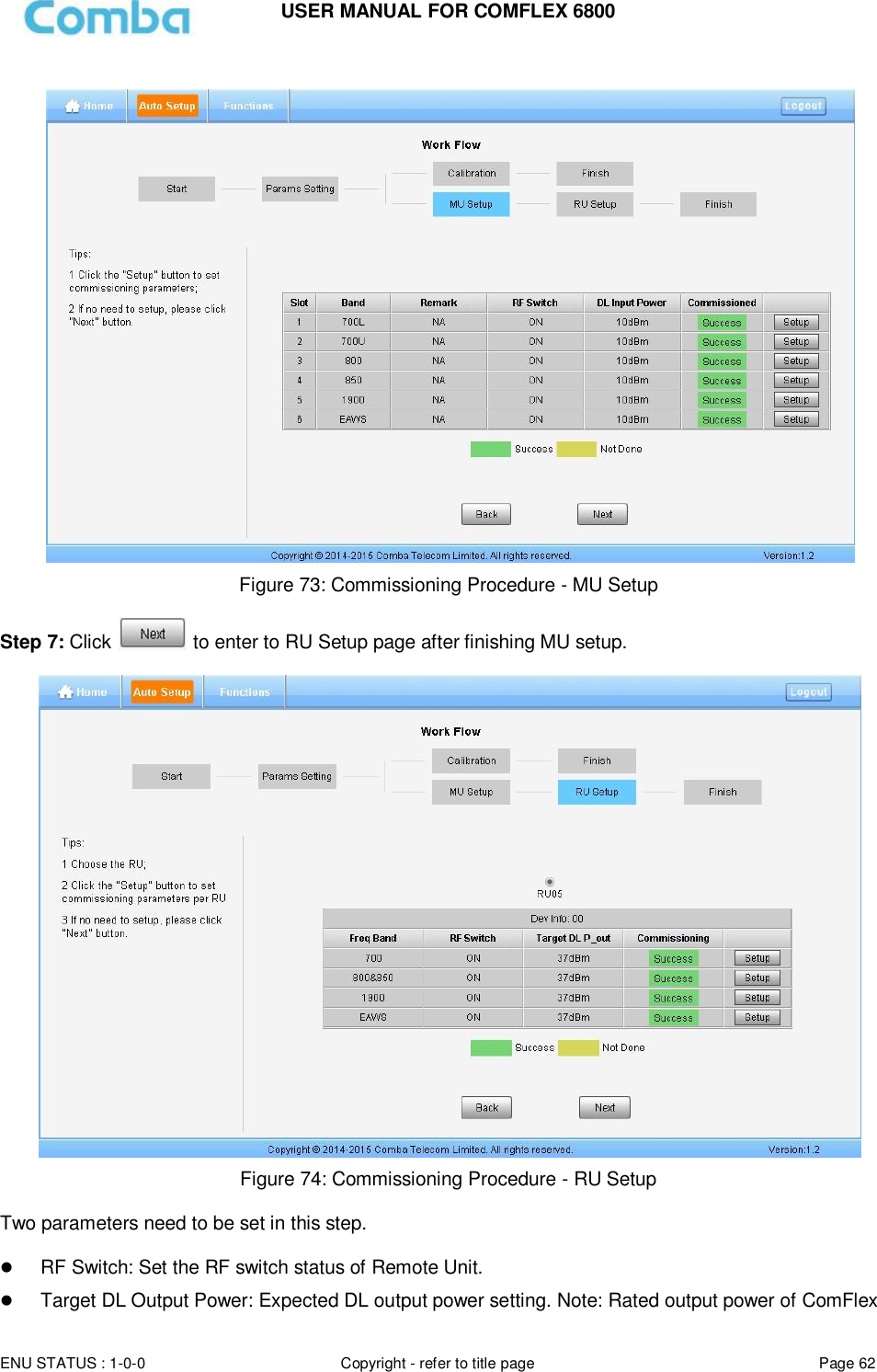
![USER MANUAL FOR COMFLEX 6800 ENU STATUS : 1-0-0 Copyright - refer to title page Page 63 Step 8: Click to enter to [Finish] page after finishing RU setup. Note: As the system calibration process is calibrated for single channel, so if there is more than one same band input, because of the power superposition, the band total output power will higer than target DL output power after the calibration is complete. The calibration work is mainly to set device to reach it’s theoretical gain, so when there are two or more same bands access into and they have the same input power level, each channel will reach it’s rated power, so the total output power will be (input A+gain) + (inputB+gain)+…+(inputN+gain). For example, if there are two 1900MHz bands acess to MU, each has 10dBm input power, the total output power of RU 1900MHz will be 30dBm+30dBm=33dBm. Refer to the method below for the gain adjustment: Suppose a band with N independent inputs, each input signal power are all X dBm. Apparently, there exists the following relationship between input and output after finished auto communication on WEB GUI: X dBm + Gain = 30dBm, then the total output power for N channels access is X dBm + Gain + 10*Log(N) = 30 + 10*Log(N), so Users need to set 10*Log(N) RFU ATT on WEB GUI for each channel. End of Section](https://usermanual.wiki/Comba-Telecom/COMFLEX-6800/User-Guide-3723167-Page-63.png)
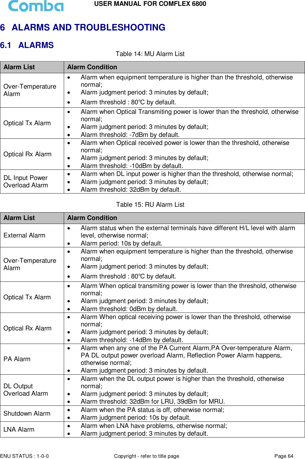
![USER MANUAL FOR COMFLEX 6800 ENU STATUS : 1-0-0 Copyright - refer to title page Page 65 6.2 TROUBLESHOOTING Following installation and commissioning, occasional operation tasks to handle alarms may be required: Table 16: MU Alarms Diagnosis Alarm condition Diagnosis Over- Temperature alarm Check temperature on WEB GUI If device temperature is over threshold, make sure environment temperature is within the envireonment temperature range that MU supported (0~40℃). Apply climatic protection to the system under severe environment. Optical TX Alarm Test MU transmit optical power Replace FOU if transmit optical power is less than -7dBm Optical RX Alarm Clean optical cable connector with pure alcohol first , reconnect and see if alarm disappears Use Optical Power Meter to test received optical power If received optical power is lower than -10dBm, test whether RU transmit optical power is normal (3~5dBm) Check if optical loss of fiber link is higher than 6.5dBo DL Input Power Overload Alarm Test DL input power of MU, if it is higher than +33dBm, lower the power below 30dBm by decreasing source output power or adding an external attenuator with proper attenuating value. Table 17: RU Alarms Diagnosis Alarm condition Diagnosis External Alarm Check to make sure if the external device connected is working normally Over- Temperature alarm Check device temperature on WEB GUI If device temperature e is over threshold, make sure environment temperature is within the envireonment temperature range that RU supported (-20~50℃). Apply climatic protection to the system under severe environment. Optical TX Alarm Test RU transmit optical power Replace FOU if transit optical power is less than 0dBm Optical RX Alarm Clean optical cable connector with pure alcohol first, reconnect and see if alarm disappears Use Optical Power Meter to test received optical power If received optical power is lower than -14dBm, test whether MU transmit optical power is normal (-4~-2dBm) Check if optical loss of fiber link is higher than 6.5dBo DL PA alarms Check PA Service Status on WEB GUI RU page, If it is [Recovery], reset PA on WEB GUI Management page, then read RU output power: If output power is exceed threshold, need to reduce gain or input power; if output power is normall, check whether antenna port VSWR is too high. If it is [Shutdown], Refer to PA Shutdown Alram DL Output Power Overload Alarm Check if output power is exceed the threshold (32dBm for LRU, 39dBm for MRU) Decrease the gain to reduce the output power PA Shutdown Alarm Make Sure the environment temperature is -20~50℃ Reset PA, if PA service status turns to [Recovery], and then refer to DL PA Alarms. If PA still shutdown, the PA module maybe damaged, please contact with Comba to replace the RU. LNA Alarm Uplink LNA modual damaged, please contact with Comba to replace the RU. End of Section](https://usermanual.wiki/Comba-Telecom/COMFLEX-6800/User-Guide-3723167-Page-65.png)