Comba Telecom RA-5700-D Master Unit of Tri-band Distributed Antenna System User Manual REV2
Comba Telecom Ltd. Master Unit of Tri-band Distributed Antenna System REV2
UserManual.wiki
>
Comba Telecom
>
RA 5700 D User Manual
User manual REV2
Navigation menu
Upload a User Manual
Namespaces
Wiki Guide
HTML
PDF
Info
Views
User Manual
Discussion / Help
Navigation
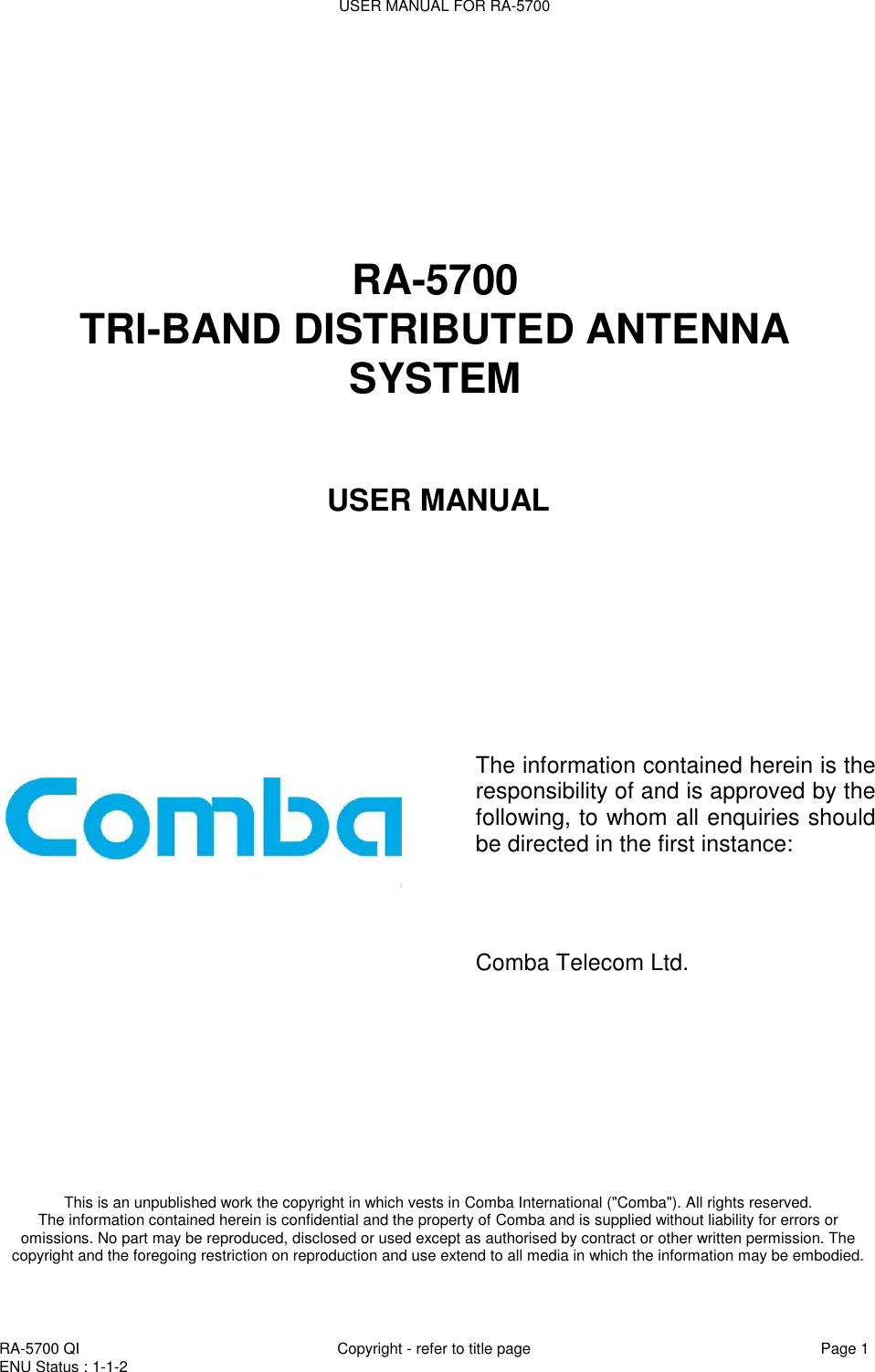
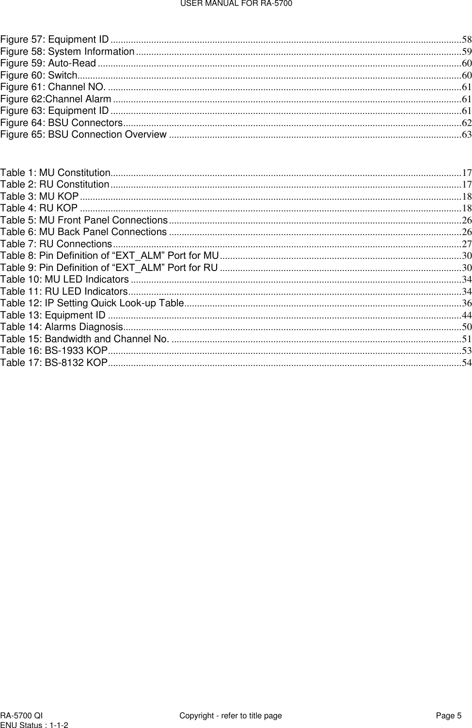
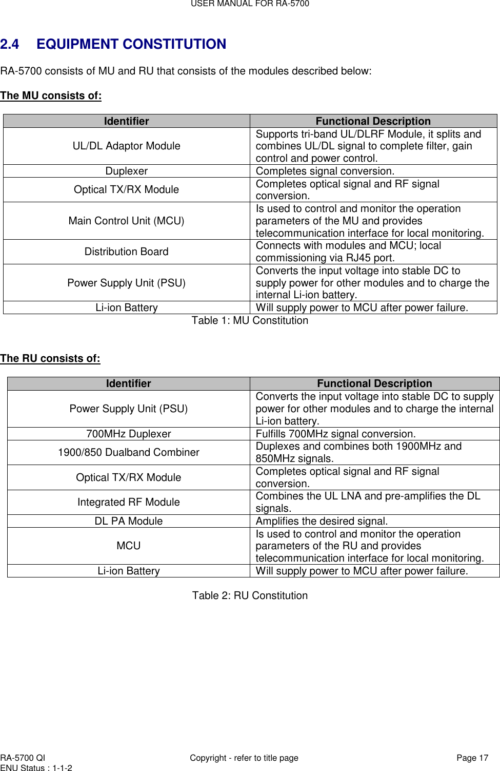
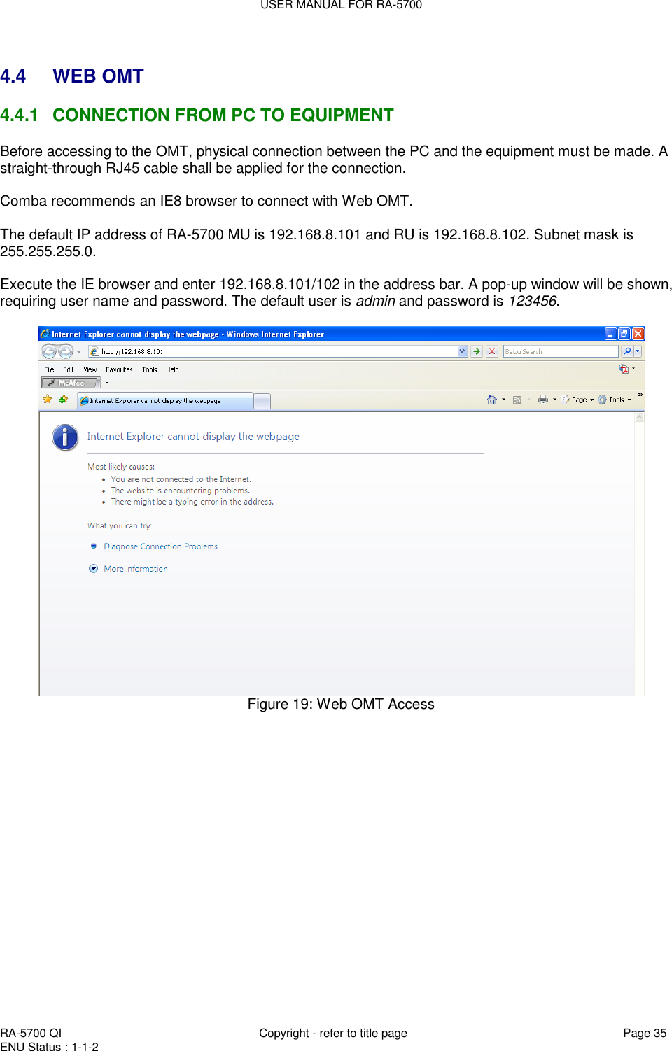
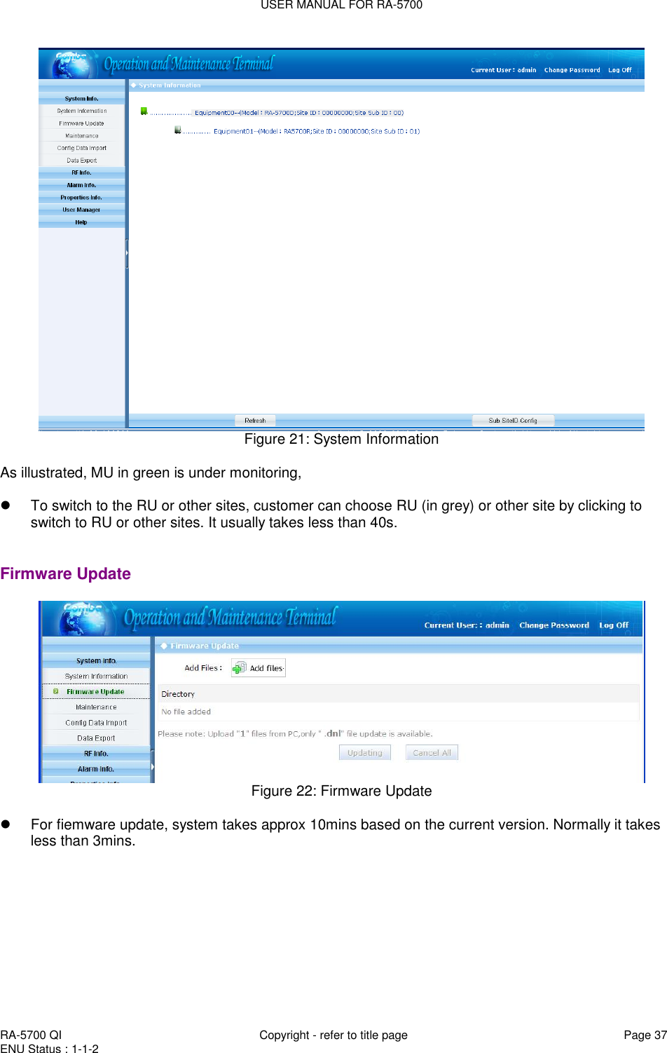
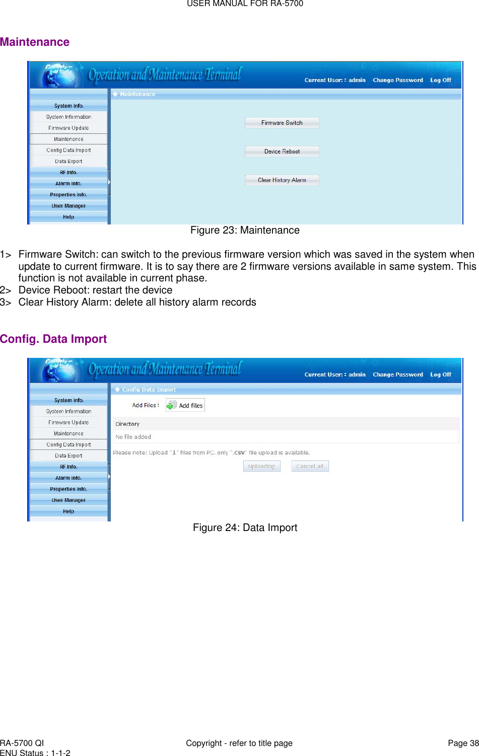
![USER MANUAL FOR RA-5700 RA-5700 QI Copyright - refer to title page Page 36 ENU Status : 1-1-2 Figure 20: Log in Items Default Value PC IP Address Automatically distributed by system PC Subnet Mask 255.255.255.0 PC Gateway Automatically distributed by system System IP Address 192.168.8.101 (for MU) / 192.168.8.102 (for RU) System Subnet Mask 255.255.255.0 User name admin Password 123456 Table 12: IP Setting Quick Look-up Table 4.4.2 OMT CONFIGURATION OMT parameters include: Common Information, RF Information, Alarm Information, Properties Information, User Manager and Help. 4.4.3 SYSTEM INFORAMTION Click on [System Information], system information will be displayed in the right interface of the OMT screen. In the interface the site ID of MU is described and the currently accessed unit is indicated.](https://usermanual.wiki/Comba-Telecom/RA-5700-D/User-Guide-1460082-Page-36.png)
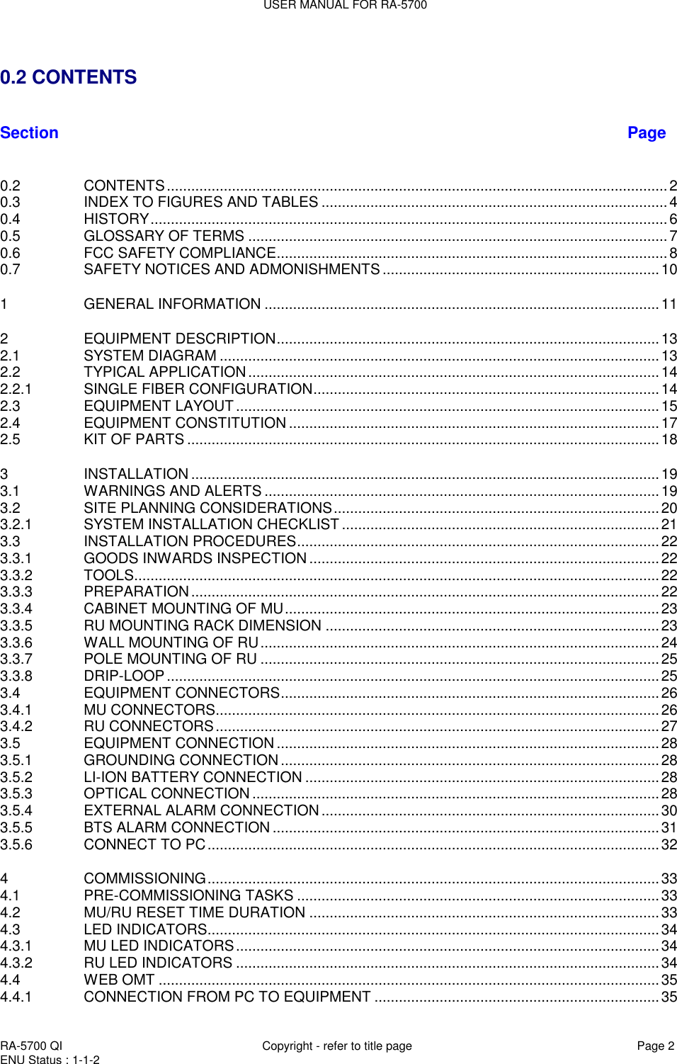
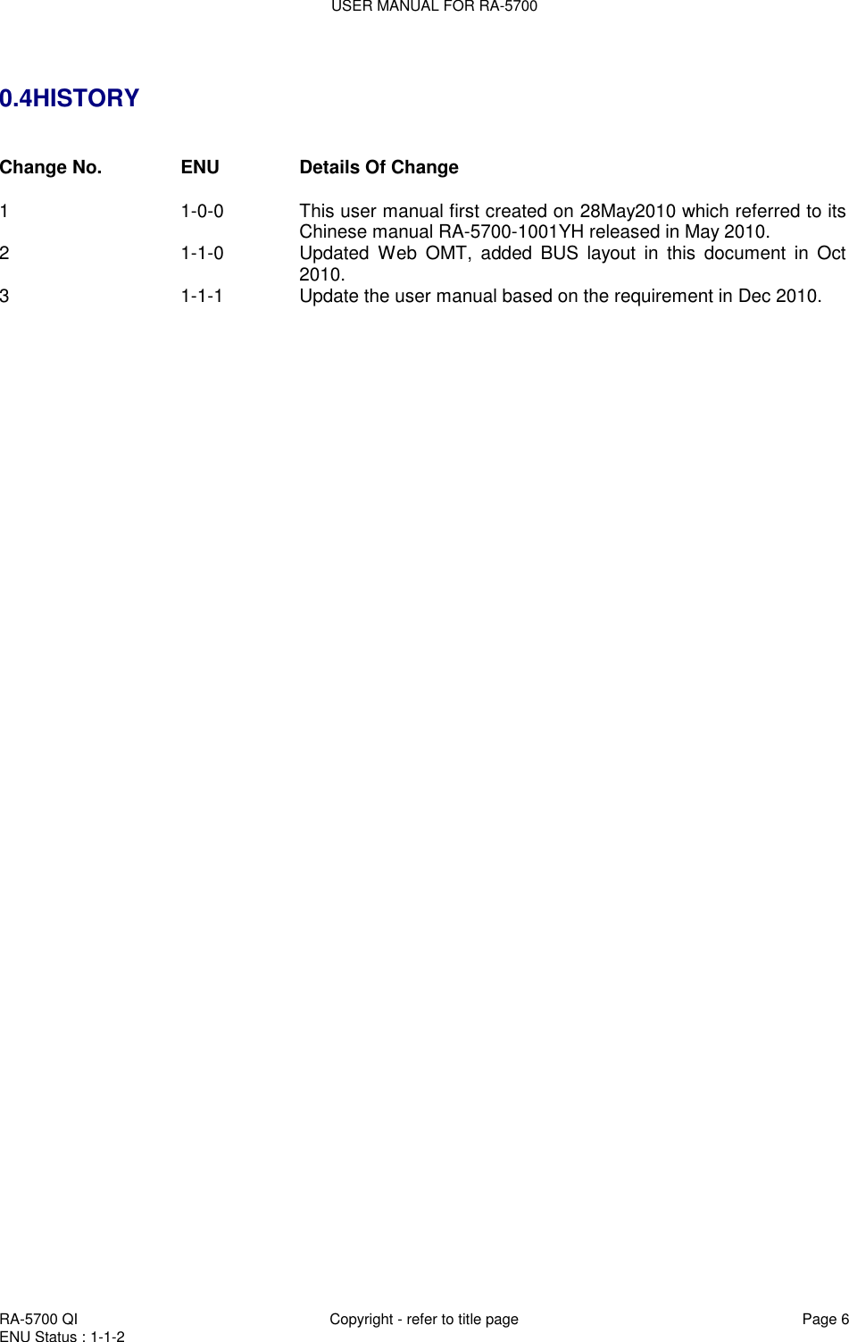
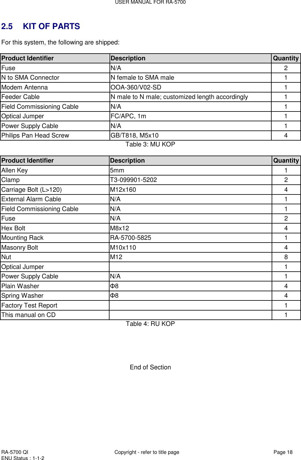
![USER MANUAL FOR RA-5700 RA-5700 QI Copyright - refer to title page Page 39 ENU Status : 1-1-2 Data Export Figure 25: Data Export [Export]: Export all site records. The records can be exported to a CSV file. 1> Config Data Export: can export the config. data and save in PC. The exported data can be input to the same kind of equipment if necessary. 2> Status Data Export: can export status data and save in PC. The data is save-only, can not import. 3> Usally, cofig a data import and export, it takes less than 5s. 4.4.4 RF INFORMATION It is recommended to configure the following RF parameters for the first installation. Switch Switch is to enable/disable power for internal modules. When user checks and sets non-RF parameters, such as checking physical antenna connection, switching off will disable equipment power temporarily to protect PA in operation. Figure 26: Switch Config: Select the required state in setting columns of RF information window for RF switch, then press [ON] or [OFF] button to finish the configuration operation.](https://usermanual.wiki/Comba-Telecom/RA-5700-D/User-Guide-1460082-Page-39.png)
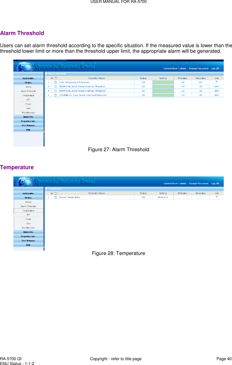
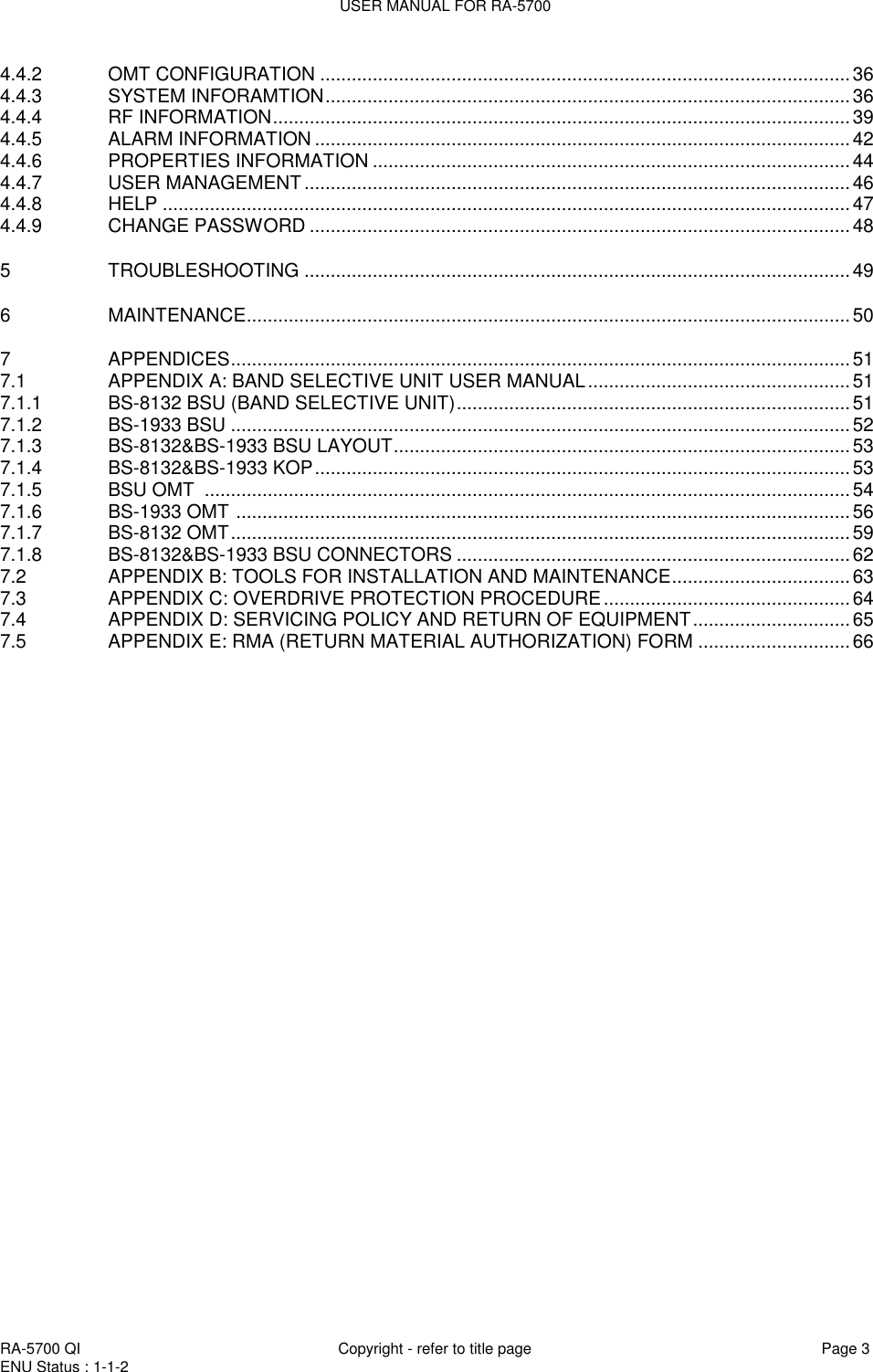
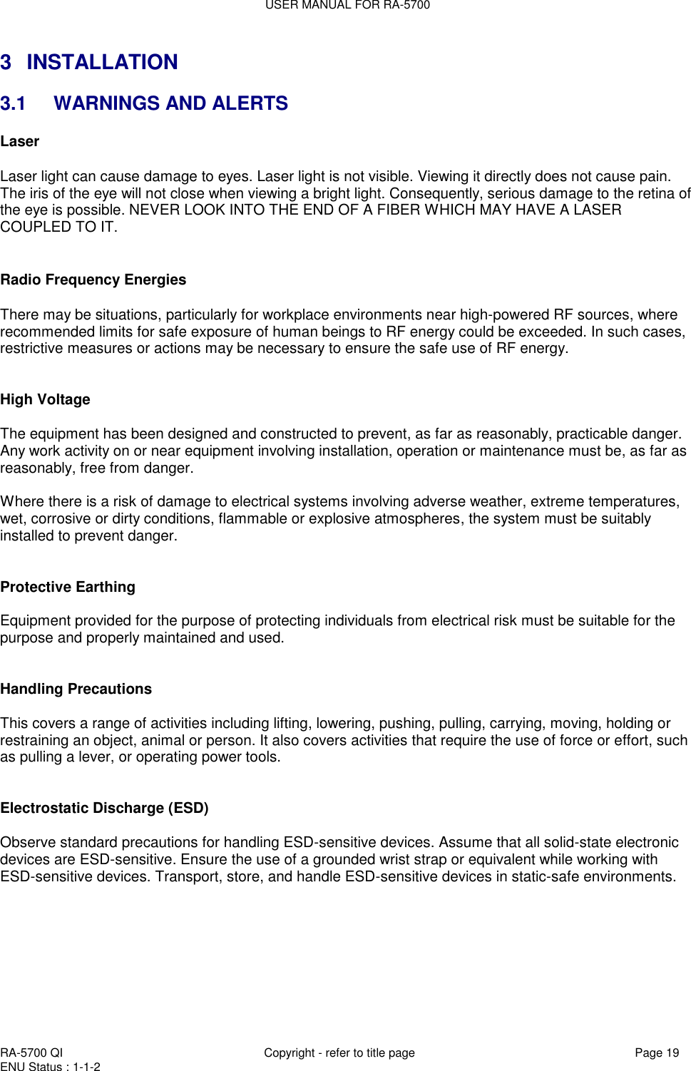
![USER MANUAL FOR RA-5700 RA-5700 QI Copyright - refer to title page Page 41 ENU Status : 1-1-2 ATT Figure 29: ATT [ATT]: read-only parameters. ATT = Rating Gain - Gain Power Figure 30: Power](https://usermanual.wiki/Comba-Telecom/RA-5700-D/User-Guide-1460082-Page-41.png)
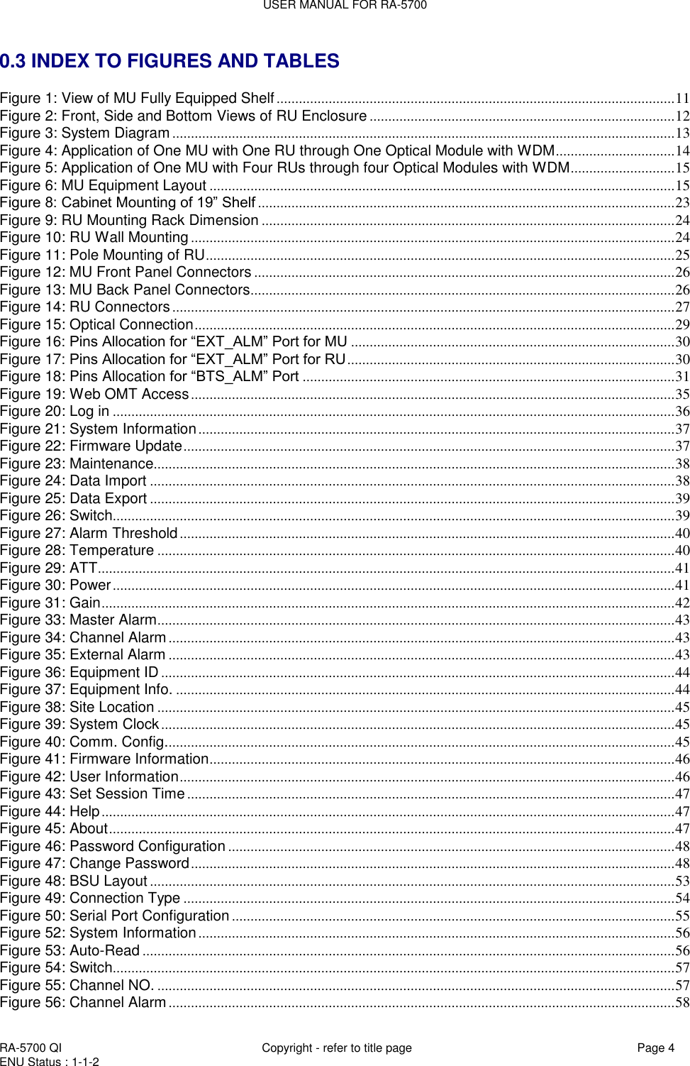
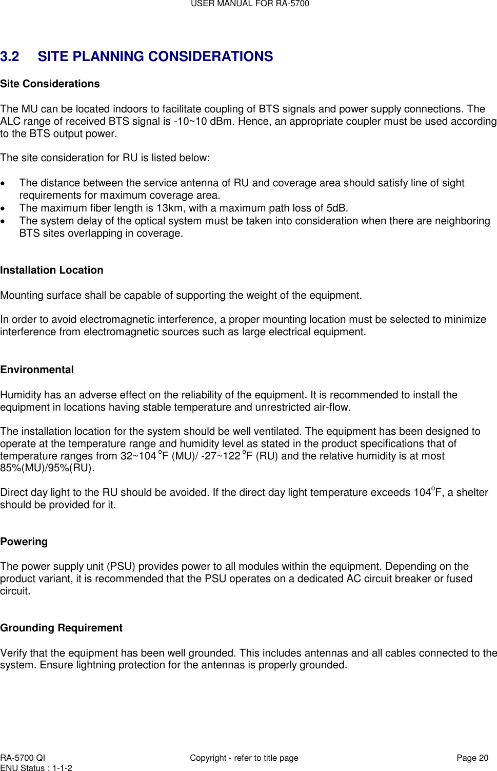
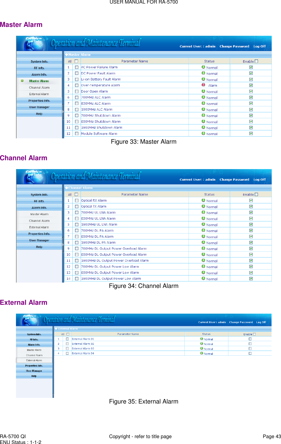
![USER MANUAL FOR RA-5700 RA-5700 QI Copyright - refer to title page Page 42 ENU Status : 1-1-2 Gain Figure 31: Gain Rating Gain: be set before delivery. Comba recommends no change of rating gain value. Gain: User can set according to the real application. Miscellaneous Figure 32: Miscellaneous 4.4.5 ALARM INFORMATION Click any tree node in [Alarm Info] group, [Alarm Information] window will appear in the right side. The figures below show the alarm information.](https://usermanual.wiki/Comba-Telecom/RA-5700-D/User-Guide-1460082-Page-42.png)
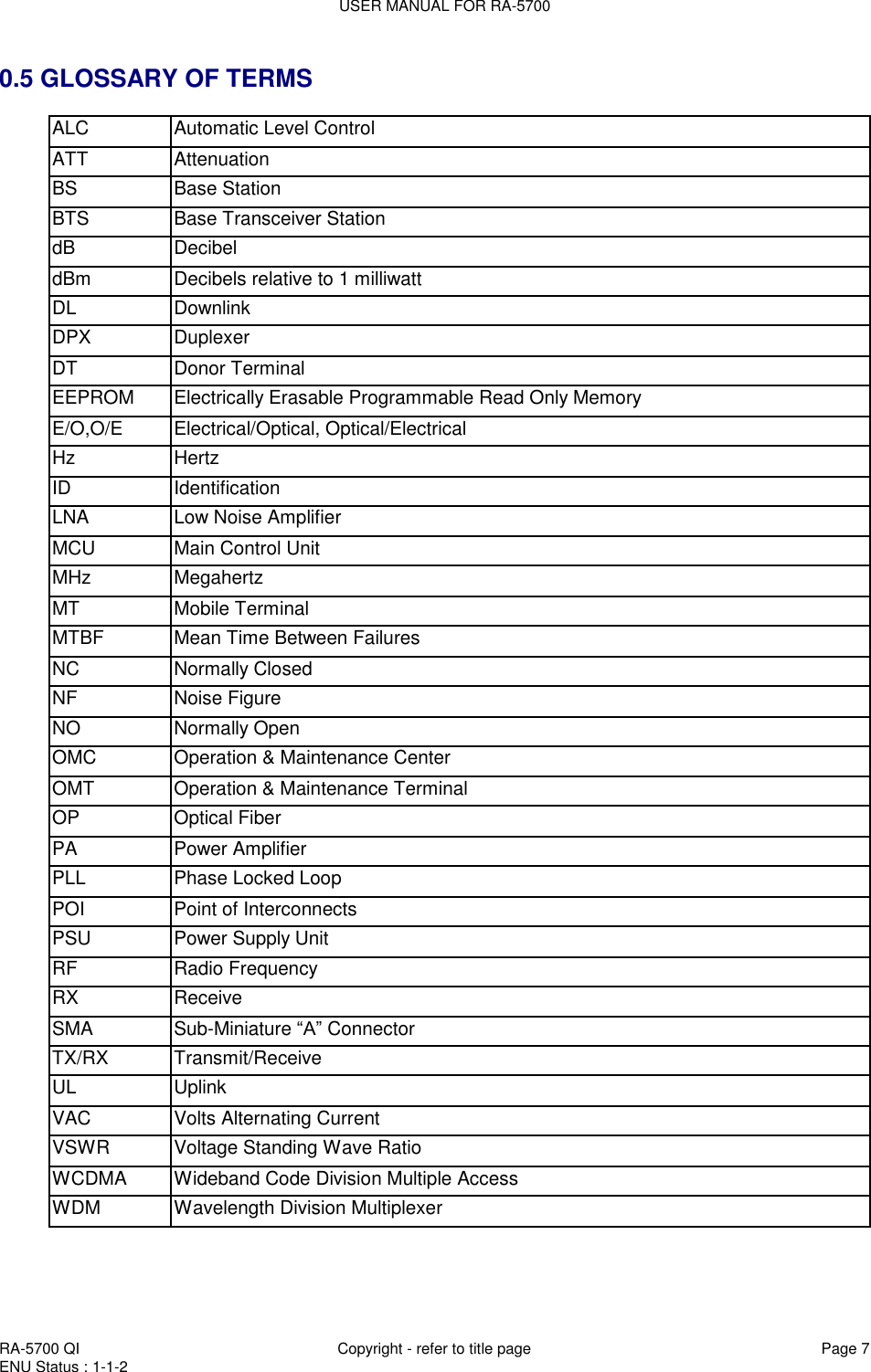
![USER MANUAL FOR RA-5700 RA-5700 QI Copyright - refer to title page Page 44 ENU Status : 1-1-2 4.4.6 PROPERTIES INFORMATION Equipment ID Equipment ID is to be configured after local commission has been completed, which includes Site ID and Site Sub ID. Item Description Site ID Site ID is the unique equipment identification. It is a hexadecimal string of eight characters in the range of [0x00000000-0xFFFFFFFF]. e.g. 12345678 Site Sub ID Site Sub ID is used for Master-Slave System. It is the unique identification of each Master/ Slave Unit and is a hexadecimal string of two characters in the range of [0x00-0xFF] For the system located with single equipment, the Site Sub ID should be 0xFF. e.g. 00 For Master-Slave system, the Site Sub ID for Master Unit is 0x00, and the Site Sub ID for each Slave Unit is represented in the range of [0x00-0xFE] in ascending order. e.g. Master Site ID: 00 Slave Site ID: 01 Table 13: Equipment ID Figure 36: Equipment ID Equipment Info. Figure 37: Equipment Info.](https://usermanual.wiki/Comba-Telecom/RA-5700-D/User-Guide-1460082-Page-44.png)
![USER MANUAL FOR RA-5700 RA-5700 QI Copyright - refer to title page Page 45 ENU Status : 1-1-2 Site Location Figure 38: Site Location [Site Location]: input the current longitude and latitude in the blank. System Clock Figure 39: System Clock [System Clock]: it shows the current time/date information. It is settable. Comm. Config The Comm. Config information requires to be manually entered by users after successful connection to the equipment. Figure 40: Comm. Config.](https://usermanual.wiki/Comba-Telecom/RA-5700-D/User-Guide-1460082-Page-45.png)
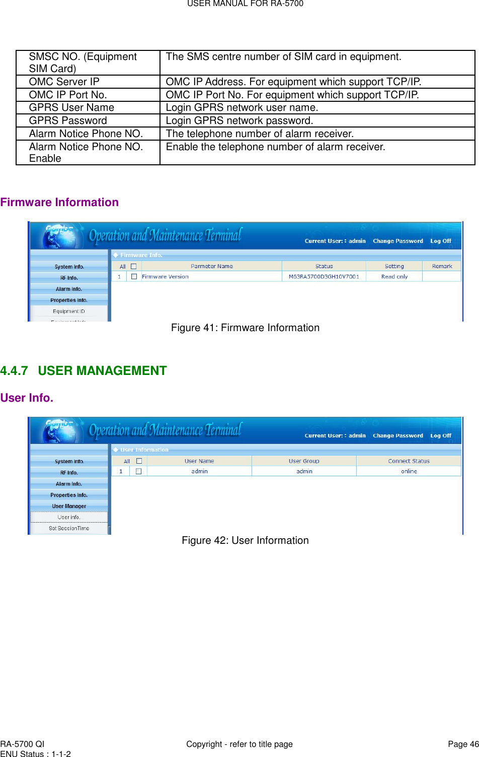
![USER MANUAL FOR RA-5700 RA-5700 QI Copyright - refer to title page Page 47 ENU Status : 1-1-2 Set Session Time Figure 43: Set Session Time [Set Session Time] is to set the automatic log-off time. 4.4.8 HELP Help Figure 44: Help About Figure 45: About](https://usermanual.wiki/Comba-Telecom/RA-5700-D/User-Guide-1460082-Page-47.png)
![USER MANUAL FOR RA-5700 RA-5700 QI Copyright - refer to title page Page 48 ENU Status : 1-1-2 4.4.9 CHANGE PASSWORD Click [User Info.]-> select the wanted user as illustrated. Figure 46: Password Configuration Sumit the request of <Edit User> buttom in the bottom, a pop-up window might shown out to indicate an on-going step. Figure 47: Change Password End of section](https://usermanual.wiki/Comba-Telecom/RA-5700-D/User-Guide-1460082-Page-48.png)
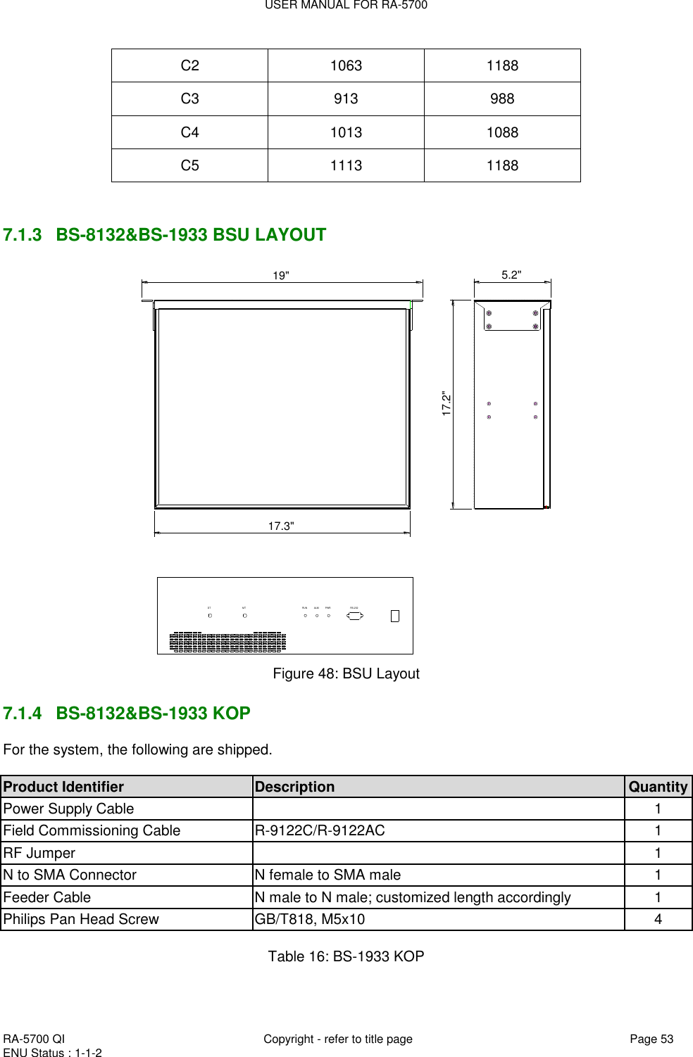
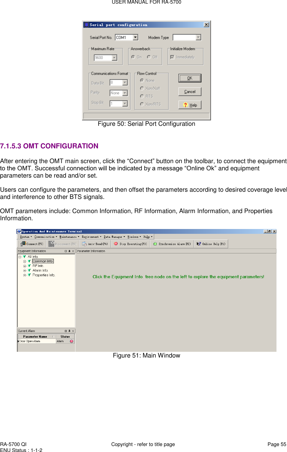
![USER MANUAL FOR RA-5700 RA-5700 QI Copyright - refer to title page Page 54 ENU Status : 1-1-2 Product Identifier Description Quantity Power Supply Cable 1 Field Commissioning Cable R-9122C/R-9122AC 1 RF Jumper 1 N to SMA Connector N female to SMA male 1 Feeder Cable N male to N male; customized length accordingly 1 Philips Pan Head Screw GB/T818, M5x10 4 Table 17: BS-8132 KOP 7.1.5 BSU OMT 7.1.5.1 LOCAL TO OMT After installing OMT software on the PC, connection to the equipment can be done locally. Double click the OMT explorer icon, the OMT Explorer main screen window will appear. 7.1.5.2 LOCAL CONNECTION TO OMT After database configuration is done successfully, the following window will pop up and select [Local connection via RS-232] for local connection. Figure 49: Connection Type Select the desired communication port and click “OK”, it will enter into the main window of OMT.](https://usermanual.wiki/Comba-Telecom/RA-5700-D/User-Guide-1460082-Page-54.png)
![USER MANUAL FOR RA-5700 RA-5700 QI Copyright - refer to title page Page 56 ENU Status : 1-1-2 7.1.6 BS-1933 OMT 7.1.6.1 Common Information System Information Click on [System Info.] within Equipment Information, system information will be displayed in the right interface of the OMT screen. Figure 52: System Information Auto-Read Customer can set which parameters to be read automatically at a particular time interval. Click on the [Auto-Read] node in the right interface the parameters will be displayed in the right interface. Select the desired parameters and click [Save] button. Input a number in the time interval field and click the adjacent [Save] button to admit the setting. Example: If the time interval is 3 seconds, then the selected alarm parameters will be read automatically every 3-second. Figure 53: Auto-Read](https://usermanual.wiki/Comba-Telecom/RA-5700-D/User-Guide-1460082-Page-56.png)
![USER MANUAL FOR RA-5700 RA-5700 QI Copyright - refer to title page Page 57 ENU Status : 1-1-2 7.1.6.2 RF Parameter It is recommended to configure the following RF parameters for the first installation. SWITCH Switch is to enable/disable power for internal modules. When user checks and sets non-RF parameters, such as checking physical antenna connection, switching off will disable equipment power temporarily to protect PA in operation. Figure 54: Switch Config: Select the required state in setting columns of RF information window for RF switch, then press [Enter] or [Config] button to finish the configuration operation. CHANNEL NO. Channel No. includes Low Edge Channel No. and High Edge Channel No. The value in [MaxValue] column is the upper limit of the range, while the value in [MinValue] column is the lower limit of the range. Figure 55: Channel NO.](https://usermanual.wiki/Comba-Telecom/RA-5700-D/User-Guide-1460082-Page-57.png)
![USER MANUAL FOR RA-5700 RA-5700 QI Copyright - refer to title page Page 58 ENU Status : 1-1-2 7.1.6.3 Alarm Information Figure 56: Channel Alarm Config: Tick the check box of [Item select] and [Enable] of the desired parameters and click [config] button to finish configuration operation. Notice: [Enable] box is to enable the alarm monitoring for system. Only if users enable the alarm by ticking the [Enable] box, the alarms can be monitored by the OMT/OMC. 7.1.6.4 Properties Information EQUIPMENT ID Equipment ID is to be configured after local commission has been completed, which includes Site ID, and Site Sub ID. Figure 57: Equipment ID See the table below for configuration details of each parameter. Item Description Site ID Site ID is the unique equipment identification. It is a hexadecimal string of eight characters in the range of [00000000~FFFFFFFF]. e.g. 00000000 Site Sub ID Site Sub ID is used for Master-Slave System. It is the unique identification of each Master/ Slave Unit and is a hexadecimal string of two characters in the range of](https://usermanual.wiki/Comba-Telecom/RA-5700-D/User-Guide-1460082-Page-58.png)
![USER MANUAL FOR RA-5700 RA-5700 QI Copyright - refer to title page Page 59 ENU Status : 1-1-2 [00~FF]. For the system located with single equipment, the Site Sub ID should be FF. For Master-Slave system, the Site Sub ID for Master Unit is 00, and the Site Sub ID for each Slave Unit is represented in the range of [01~FE] in ascending order. e.g. Master Site ID: 00, Slave Site ID: 01 7.1.7 BS-8132 OMT 7.1.7.1 Common Information System Information Click on [System Info.] within Equipment Information, system information will be displayed in the right interface of the OMT screen. Figure 58: System Information Auto-Read Customer can set which parameters to be read automatically at a particular time interval. Click on the [Auto-Read] node in the right interface the parameters will be displayed in the right interface. Select the desired parameters and click [Save] button. Input a number in the time interval field and click the adjacent [Save] button to admit the setting. Example: If the time interval is 3 seconds, then the selected alarm parameters will be read automatically every 3-second.](https://usermanual.wiki/Comba-Telecom/RA-5700-D/User-Guide-1460082-Page-59.png)
![USER MANUAL FOR RA-5700 RA-5700 QI Copyright - refer to title page Page 60 ENU Status : 1-1-2 Figure 59: Auto-Read 7.1.7.2 RF Parameter It is recommended to configure the following RF parameters for the first installation. SWITCH Switch is to enable/disable power for internal modules. When user checks and sets non-RF parameters, such as checking physical antenna connection, switching off will disable equipment power temporarily to protect PA in operation. Figure 60: Switch Config: Select the required state in setting columns of RF information window for RF switch, then press [Enter] or [Config] button to finish the configuration operation. CHANNEL NO. Channel No. includes Low Edge Channel No. and High Edge Channel No. The value in [MaxValue] column is the upper limit of the range, while the value in [MinValue] column is the lower limit of the range.](https://usermanual.wiki/Comba-Telecom/RA-5700-D/User-Guide-1460082-Page-60.png)
![USER MANUAL FOR RA-5700 RA-5700 QI Copyright - refer to title page Page 61 ENU Status : 1-1-2 Figure 61: Channel NO. 7.1.7.3 Alarm Information Figure 62:Channel Alarm Config: Tick the check box of [Item select] and [Enable] of the desired parameters and click [config] button to finish configuration operation. Notice: [Enable] box is to enable the alarm monitoring for system. Only if users enable the alarm by ticking the [Enable] box, the alarms can be monitored by the OMT/OMC. 7.1.7.4 Properties Information EQUIPMENT ID Equipment ID is to be configured after local commission has been completed, which includes Site ID, and Site Sub ID. Figure 63: Equipment ID](https://usermanual.wiki/Comba-Telecom/RA-5700-D/User-Guide-1460082-Page-61.png)
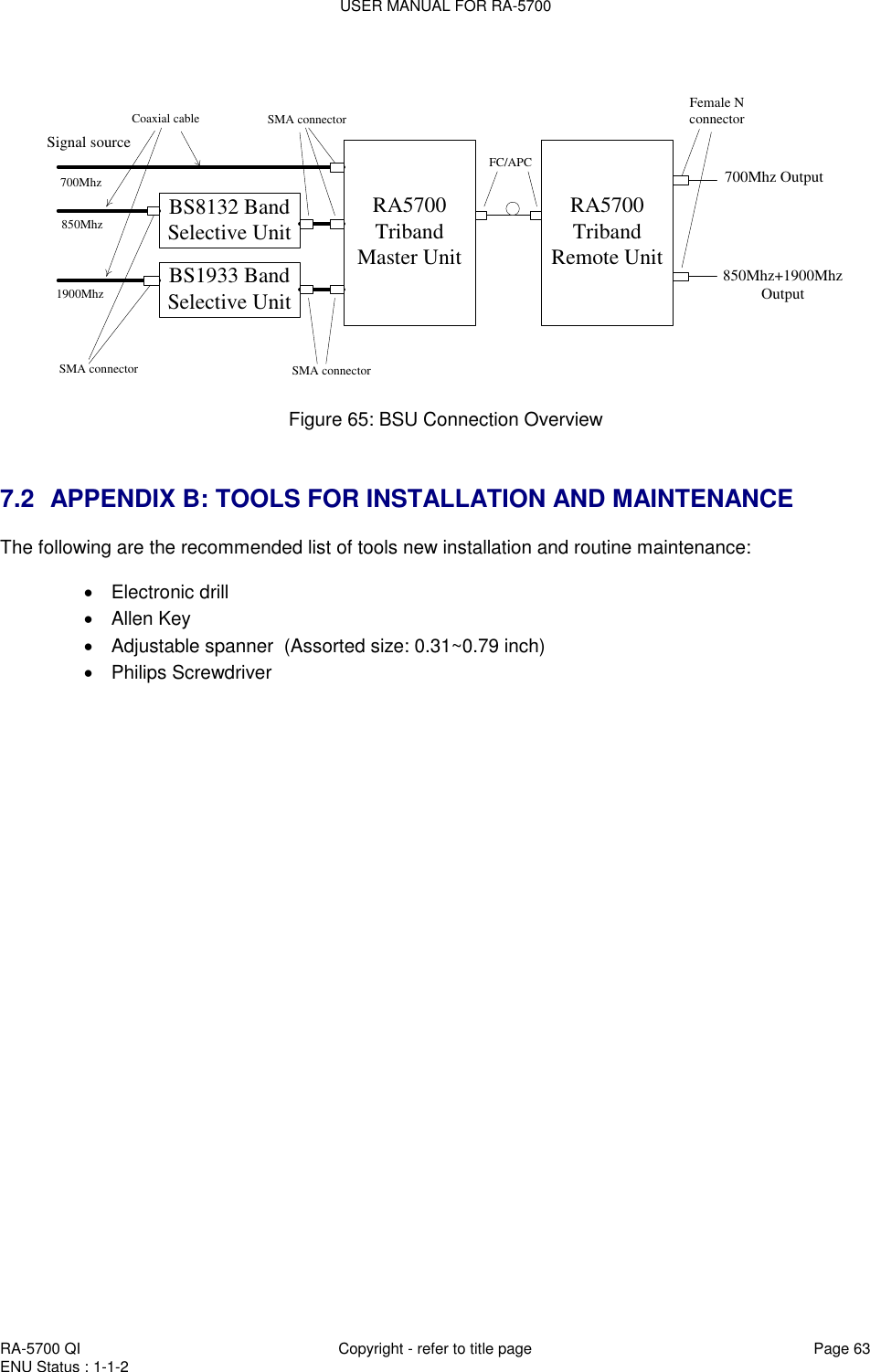
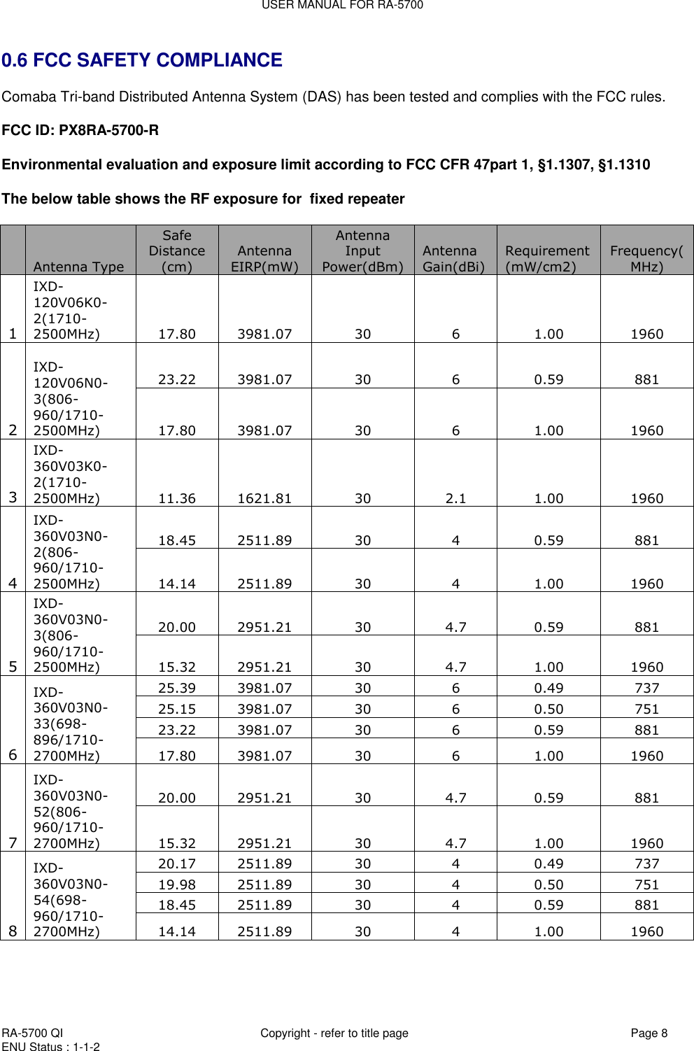
![USER MANUAL FOR RA-5700 RA-5700 QI Copyright - refer to title page Page 62 ENU Status : 1-1-2 See the table below for configuration details of each parameter. Item Description Site ID Site ID is the unique equipment identification. It is a hexadecimal string of eight characters in the range of [00000000~FFFFFFFF]. e.g. 00000000 Site Sub ID Site Sub ID is used for Master-Slave System. It is the unique identification of each Master/ Slave Unit and is a hexadecimal string of two characters in the range of [00~FF]. For the system located with single equipment, the Site Sub ID should be FF. For Master-Slave system, the Site Sub ID for Master Unit is 00, and the Site Sub ID for each Slave Unit is represented in the range of [01~FE] in ascending order. e.g. Master Site ID: 00, Slave Site ID: 01 7.1.8 BS-8132&BS-1933 BSU CONNECTORS DTFront PanelMT RUN ALM PWR RS232AC 100V-240V50Hz/60HzRear Panel Figure 64: BSU Connectors Identifier Functional Description DT SMA connector, connects with BTS MT SMA connector, BS-8132_MT connects with RA-5700D_850MHz connector while BS-1933_MT connects with RA-5700D_1900MHz connector RUN Operation indicator ALM Alarm indicator PWR Power supply indicator RS232 DB9 connector, connects to PC via engineering OMT. AC 100-240V 50Hz~50Hz Power supply](https://usermanual.wiki/Comba-Telecom/RA-5700-D/User-Guide-1460082-Page-62.png)