Comba Telecom RD-2020 RD2020 AWS Bandwidth Adjustable Repeater User Manual RD 2020 QI 1 0 0
Comba Telecom Ltd. RD2020 AWS Bandwidth Adjustable Repeater RD 2020 QI 1 0 0
UserManual.wiki
>
Comba Telecom
>
RD 2020 User Manual
PX8RD-2020 User manual
Navigation menu
Upload a User Manual
Namespaces
Wiki Guide
HTML
PDF
Info
Views
User Manual
Discussion / Help
Navigation

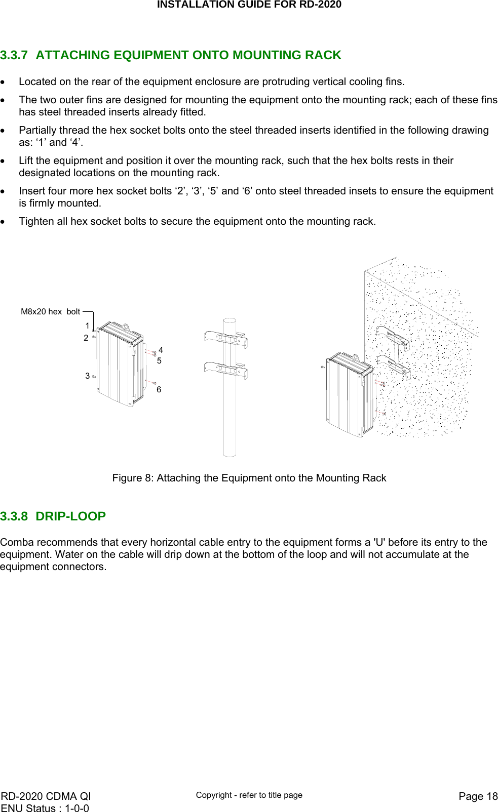
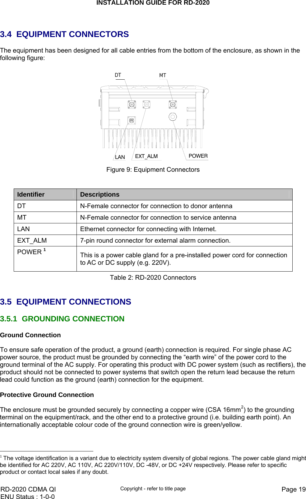
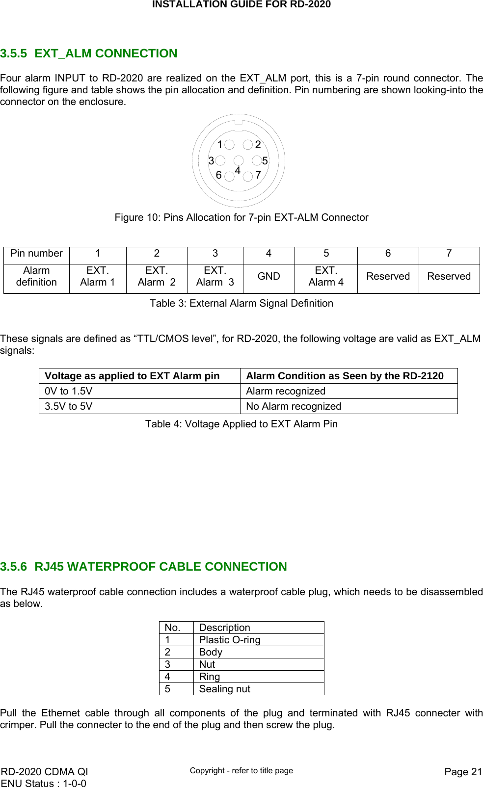

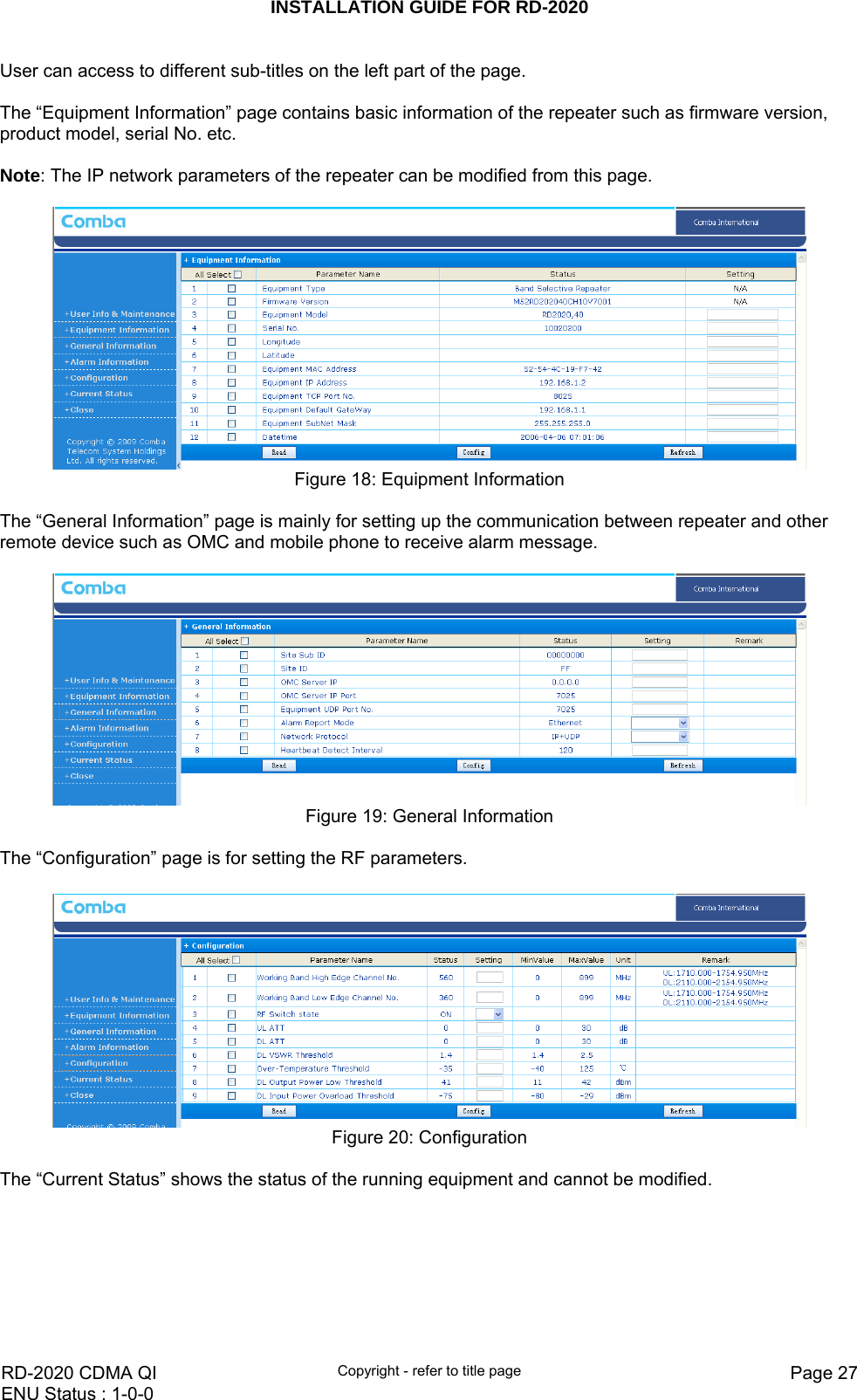
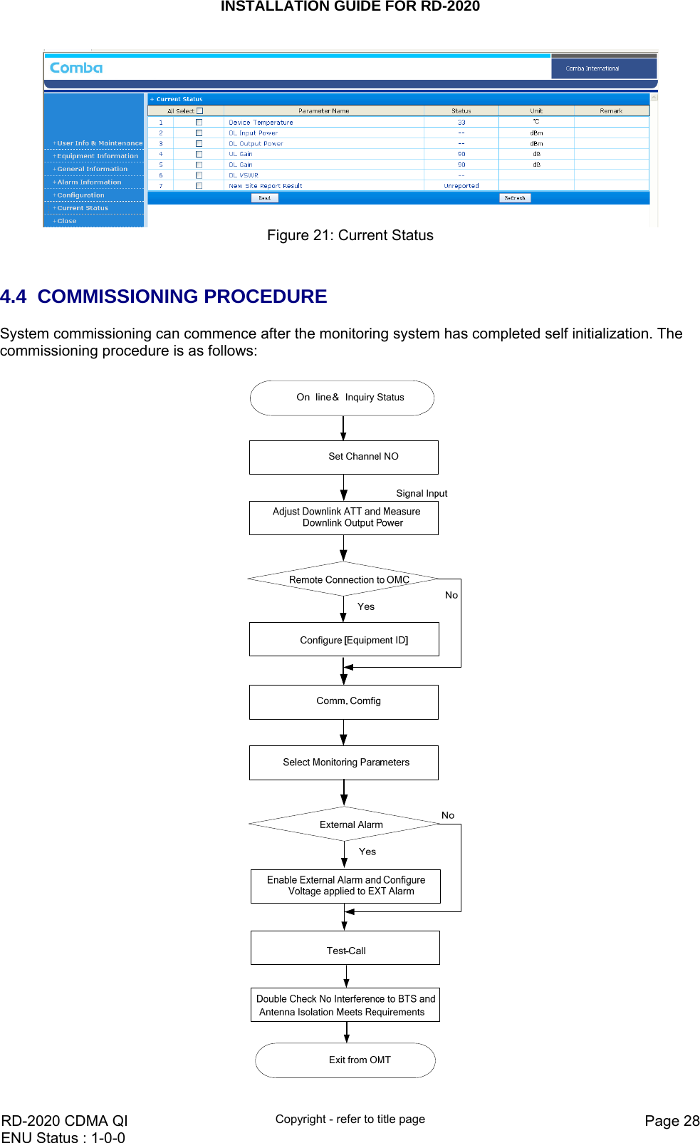
![INSTALLATION GUIDE FOR RD-2020 RD-2020 CDMA QI Copyright - refer to title page Page 29ENU Status : 1-0-0 Commissioning Tasks Observation 1. On-line and Inquiry status z Connect to repeater from PC via OMT. 2. Set Channel No. z Keep RF switch ON and set the channel number of the repeater’s operating frequency. 3. Adjust Downlink Output Power and align donor antenna z Observe DL input power from measured value. Align the direction of donor antenna until the DL input power reading is maximized. z Note: To ensure that the measured DL input power is accurate, one should set the DL ATT to “0” before performing the check. 4. Configure [Equipment ID] z Go to [Properties Info] and set [Equipment ID]. 5. Comm. Config z Enable the power supply by selecting “On” in [RF] -> [Switch]; go to [Properties Info.] -> [Comm. Config.] and set OMC Phones No. , the service No. of SMSC, Report Mode. 6. Select Monitoring Parameters z Select the equipment controlled and monitored parameters. z If the external devices are connected to the equipment for management, please enable in the [External Alarm Info.] Interface. 7. Test coverage area field intensity and adjust service antenna. z Use test-handset to verify field intensity within the coverage area. If needed, realign the service antenna to achieve the desired coverage. z Note: If during operation, the equipment gain could not be set to maximum or the output power is not high enough due to insufficient donor and service antennas isolation, then the antennas’ position should be changed to increase isolation. If the output power is too high and ALC is activated, then adjust the DL ATT to achieve optimal DL Gain. 8. Verify UL gain and ensure test call produces good voice quality and there is no interfering BTS z Adjust UL gain and perform test calls. Typically, the UL gain is set around 5dB less than DL gain. Perform test calls in the coverage area while adjusting UL gain if required. z Note: If the repeater is near the BTS and the test call performance is poor, this may be due to UL noise interference to the BTS. Users can calculate and determine if the repeater UL noise will interfere with the BTS. z Verify again that there is no unacceptable interference to BTS. Table 7: Commissioning End of section](https://usermanual.wiki/Comba-Telecom/RD-2020/User-Guide-1390032-Page-29.png)