Comba Telecom RD-8132 RD8132 CDMA Repeater User Manual RD 8132 QI 1 0 0
Comba Telecom Ltd. RD8132 CDMA Repeater RD 8132 QI 1 0 0
UserManual.wiki
>
Comba Telecom
>
RD 8132 User Manual
PX8RD-8132 User Manual-Rev4
Navigation menu
Upload a User Manual
Namespaces
Wiki Guide
HTML
PDF
Info
Views
User Manual
Discussion / Help
Navigation
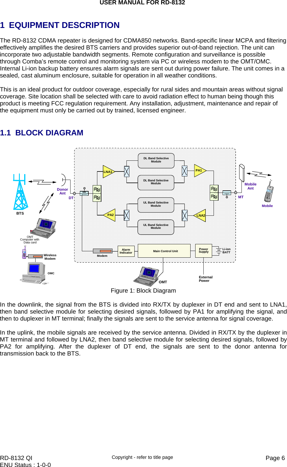
![USER MANUAL FOR RD-8132 RD-8132 QI Copyright - refer to title page Page 14ENU Status : 1-0-0 3 OMT The equipment can be monitored and controlled by OMT software running on a local PC with local commissioning cable, remote connection to the equipment via wireless GSM / CDMA network. z OMT software running on a local PC with serial connection to the equipment. z OMC (optional) software with remote connection to the equipment over wireless GSM / CDMA network. This chapter is to introduce how to apply local and remote connection to OMT for the first installation, for the detailed OMT information, please refer to OMT user manual and other references. Notice: The OMC software with remote connection to the equipment over wireless GSM / CDMA network is optional for customers. 3.1 LOCAL AND REMOTE CONNECTIONS TO OMT After installing OMT software on the PC, connection to the equipment can be done locally or remotely. Double click the OMT exlorer icon, the OMT Explorer main screen window will appear. 3.1.1 LOCAL CONNECTION TO OMT After databse configuration is done successfully, the following window will pop up and select [Local connection via RS-232] for local connection. Figure 9: Connection Type Select the desired communication port and click “OK”, it will enter into the main window of OMT. Figure 10: Serial Port Configuration](https://usermanual.wiki/Comba-Telecom/RD-8132/User-Guide-1251300-Page-14.png)
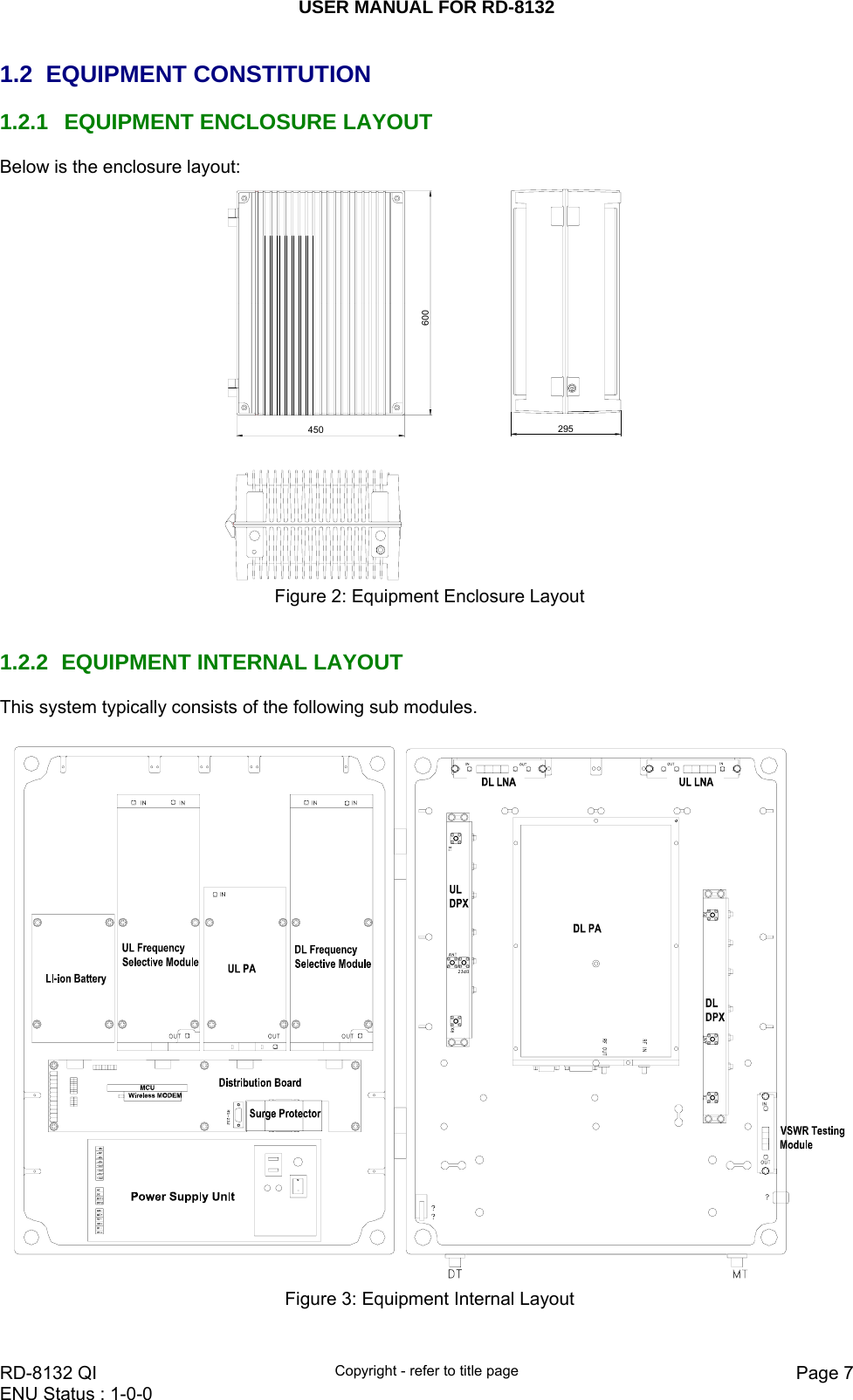
![USER MANUAL FOR RD-8132 RD-8132 QI Copyright - refer to title page Page 15ENU Status : 1-0-0 3.1.2 REMOTE CONNECTION TO OMT If remote connection is needed, users can select [Remote connection via modem] in connection type window. Select desired serial port and click “OK” in [Serial Port Configuration] window to go to OMT main window and start modem initialization. Click “connect” and the [Remote Connection] window will show up. Figure 11: Remote Connection Config: Enter the correct phone number (Users don't have to enter the password) and click “connect”, it will be connected remotely. Notice: Please enable the SIM card to support Circuit Switch Data. 3.2 OMT CONFIGURATION After entering the OMT main screen, click the “Connect” button on the toolbar, to connect the equipment to the OMT. Successful connection will be indicated by a message “Online Ok” and equipment parameters can be read and/or set. Users can configure the parameters, and then offset the parameters according to desired coverage level and interference to other BTS signals. OMT parameters include: Common Information, RF Information, Alarm Information, and Properties Information. Figure 12: OMT Main Window](https://usermanual.wiki/Comba-Telecom/RD-8132/User-Guide-1251300-Page-15.png)
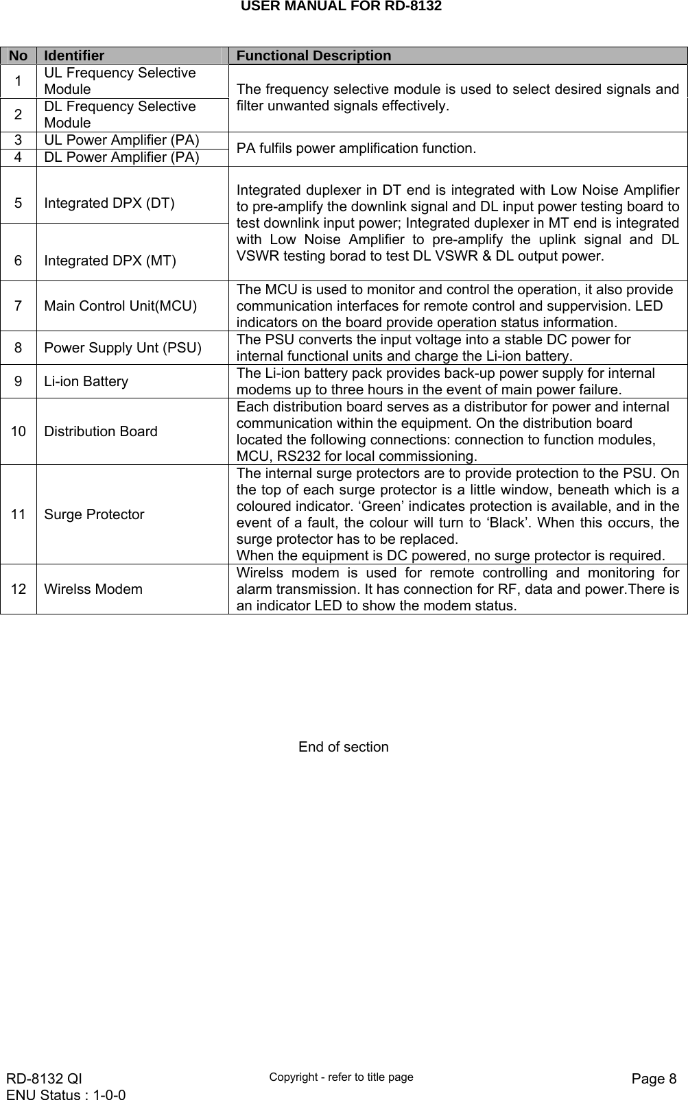
![USER MANUAL FOR RD-8132 RD-8132 QI Copyright - refer to title page Page 16ENU Status : 1-0-0 3.3 RF PARAMETER It is recommended to configure the following RF parameters for the first installation. 3.3.1 SWITCH Switch is to enable/disable power for carrier1,carrier2, RF and self-oscillation. When user checks and sets non-RF parameters, such as checking physical antenna connection, switching off will disable equipment power temporarily to protect PA in operation. Figure 13: Switch Config: Select the required state in setting columns of RF information window for RF switch, then press [Enter] or [Config] button to finish the configuration operation. 3.3.2 CHANNEL NO. Channel No. includes Low Edge Channel No. and High Edge Channel No of working band 1/ 2. The value in [MaxValue] column is the upper limit of the range, while the value in [MinValue] column is the lower limit of the range. The UL/DL Channel No.setting range: 1011~1023, 1~779 e.g. Working Band Low Edge Channel No. = 160(874.8MHz) Working Band High Edge Channel No. = 611(888.33MHz) Bandwidth=14.76MHz (inclosing 12 channals) Figure 14: Channel No.](https://usermanual.wiki/Comba-Telecom/RD-8132/User-Guide-1251300-Page-16.png)
![USER MANUAL FOR RD-8132 RD-8132 QI Copyright - refer to title page Page 17ENU Status : 1-0-0 Config: Enter the required value in setting columns and click [Config] button to finish the configuration operation. There are two methods to insert the channel number: z Insert the desired channel number (within the setting range) into the [Setting] column directly z Right click the [Setting] column, the [Frequency Calculator] dialogue window seen as below will pop-up, insert the desired channel number. Then the corresponding frequency will turn up automatically. This function makes it easier for user to configure. Figure 15: Frequency Calculator 3.3.3 ATT ATT adjustment includes UL/DL ATT adjustment. The purpose of adjusting the ATT is to adjust system gain. DL/UL ATT 1/2 setting range: 0~30dB Figure 16: ATT Config: Select the required value in setting columns of RF information window for ATT, and press [Enter] or [Config] button to finish the configuration operation. 3.3.4 ALARM THRESHOLD Alarm Threshold includes Power threshold, Temperature threshold and VSWR threshold. Users can set alarm threshold according to the specific situation. If the measured value is lower than the threshold lower limit or more than the threshold upper limit, the appropriate alarm will be generated.](https://usermanual.wiki/Comba-Telecom/RD-8132/User-Guide-1251300-Page-17.png)
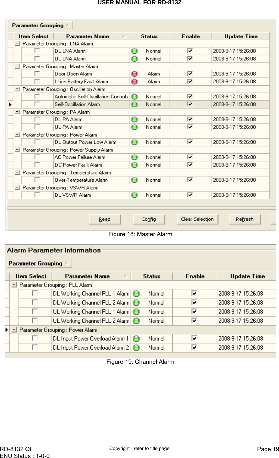
![USER MANUAL FOR RD-8132 RD-8132 QI Copyright - refer to title page Page 18ENU Status : 1-0-0 Figure 17: Alarm Threshold Config: Enter the required value in setting columns of RF information window for Alarm threshold, and press [Enter] or [Config] button to finish the configuration operation. Notice: The input value must be in the range of power threshold. The DL VSWR threshold setting range is available for only three values: 1.5, 2.0 and 2.5. 3.3.5 ALARM INFORMATION Alarm information operation is to select alarm parameters for monitoring. Alarm parameters include Master Alarm, Channel Alarm and External Alarm. Click any tree node in [Alarm Info] group, [Alarm Parameter Information] window will appear in the right side. The picture below shows the master alarm information. Alarm Threshold Setting Range Initial Setting DL Output Power Low Threshold 14~45dBm 14dBm DL Input Power Overload Threshold -70~-49dBm -49dBm DL Input Power Low Threshold -70~-49dBm -49dBm PA Over-Temperature Threshold -40~125 oC 80 oC DL VSWR Threshold 1.5, 2.0, 2.5 2.0](https://usermanual.wiki/Comba-Telecom/RD-8132/User-Guide-1251300-Page-18.png)
![USER MANUAL FOR RD-8132 RD-8132 QI Copyright - refer to title page Page 20ENU Status : 1-0-0 Figure 20: External Alarm Config: Tick the check box of [Item select] and [Enable] of the desired parameters and click [config] button to finish configuration operation. Notice: [Enable] box is to enable the alarm monitoring for system. Only if users enable the alarm by ticking the [Enable] box, the alarms can be monitored by the OMT/OMC. On the MCU, if any alarm is generated and this alarm is also enabled in [Enable] box, LED H2 turns RED; while it is OFF when normal working. On the OMT/OMC window, [Alarm Status] indicator keeps GREEN if no alarm and turns RED if an alarm is generated. Please notice that if the desired alarm is not enabled in [Enable] box, even if this alarm is generated, it keeps in GREEN in the OMT/OMC interface and LED H2 on MCU keeps OFF as well. 3.4 PROPERTIES INFO. 3.4.1 EQUIPMENT ID Equipment ID is to be configured after local commission has been completed, which includes Site ID, and Site Sub ID. Figure 21: Equipment ID See the table below for configuration details of each parameter. Item Description Site ID Site ID is the unique equipment identification. It is a hexadecimal string of eight characters in the range of [00000000~FFFFFFFF]. e.g. 00000000 Site Sub ID Site Sub ID is used for Master-Slave System. It is the unique identification of each Master/ Slave Unit and is a hexadecimal string of two characters in the range of](https://usermanual.wiki/Comba-Telecom/RD-8132/User-Guide-1251300-Page-20.png)
![USER MANUAL FOR RD-8132 RD-8132 QI Copyright - refer to title page Page 21ENU Status : 1-0-0 [00~FF]. For the system located with single equipment, the Site Sub ID should be FF. For Master-Slave system, the Site Sub ID for Master Unit is 00, and the Site Sub ID for each Slave Unit is represented in the range of [01~FE] in ascending order. e.g. Master Site ID: 00, Slave Site ID: 01 3.4.2 COMM. CONFIG If the equipment is to be monitored by OMC software over wireless GSM / CDMA network, users must finish the [Comm. Config.] in the next step. The Comm. Config information requires to be manually entered by users after successful connection to the equipment. Figure 22: Com. Config. See the table below for configuration details of each parameter. Item Description Checking Control Select “Enable” or “Disable” from the drop down menu as shown to enable or disable the Phone Number Authentication feature. Refer to [Phone No.] in details. OMC Server IP Based on the current network conditions, users can enter the IP address information of the equipment, which is connected to the OMT/OMC via Ethernet. This connection via Ethernet is not available at this stage. Phone No. This is designed for authentication purpose when remote connection via modem is required. It is the phone number to dial the equipment. Only the phone number pre-defined in this field, will it be allowed to dial the equipment. It is required to manually enter the phone number. Up to 5 phone numbers are allowed. The use of phone number authentication can avoid unauthorized use of the OMT. In addition, it can prevent the equipment receiving piles of spam short messages, thus help the operator greatly reduce the cost. Report Config The Report No. is the SIM card number of the modem built into the OMC Server computer.The equipment will send alarm SMS to this number. If remote communication is needed via modem, users have to enable SMS mode and set the report phone No. by entering the SIM card number of the equipment built-in modem. SMSC No. It specifies the SMS center. Users have to set the service No. of SMSC for the first installation, so that the alarms can be sent to OMC.](https://usermanual.wiki/Comba-Telecom/RD-8132/User-Guide-1251300-Page-21.png)
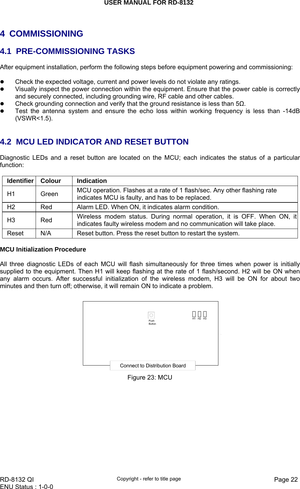
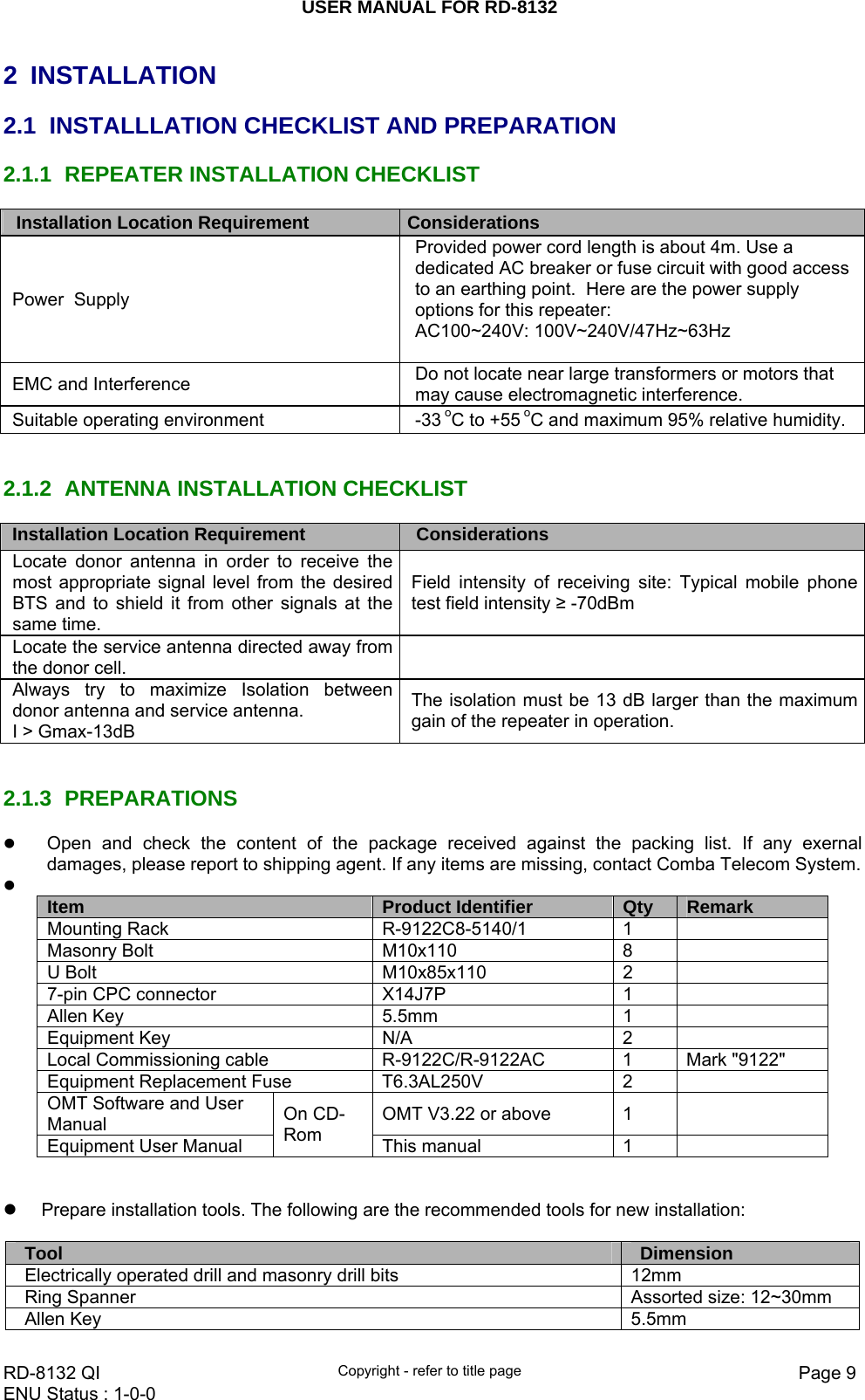
![USER MANUAL FOR RD-8132 RD-8132 QI Copyright - refer to title page Page 23ENU Status : 1-0-0 4.3 COMMISSIONING PROCEDURE System commissioning can commence after the monitoring system has completed self initialization. The commissioning procedure is as follows: On- line & Inquiry StatusExternal AlarmYesEnable External Alarm and Configure Voltage applied to EXT AlarmSet Channel NO.Adjust Downlink ATT and Measure Downlink Output PowerSignal InputExit from OMTRemote Connection to OMCYesConfigure [Equipment ID]Comm. ComfigSelect Monitoring ParametersNoNoTest-CallDouble Check No Interference to BTS and Antenna Isolation Meets Requirements](https://usermanual.wiki/Comba-Telecom/RD-8132/User-Guide-1251300-Page-23.png)
![USER MANUAL FOR RD-8132 RD-8132 QI Copyright - refer to title page Page 24ENU Status : 1-0-0 Commissioning Tasks Observation 1. On-line and Inquiry status z Activate the OMT Main window. The system Initialization will completed in about 2 minutes. z Click “Connect” button to enquire the repeater’s status. Proceed if there is no alarm; else check the failure and attend to the alarm. 2. Set Channel No. z Keep RF switch ON and set the channel number of the repeater’s operating frequency. 3. Adjust Downlink Output Power and align donor antenna z Observe DL input power from measured value. Align the direction of donor antenna until the DL input power reading is maximized. z Note: To ensure that the measured DL input power is accurate, one should set the DL ATT to “0” before performing the check. 4. Configure [Equipment ID] z Go to [Properties Info] and set [Equipment ID]. 5. Comm. Config z Enable the power supply by selecting “On” in [RF] -> [Switch]; go to [Properties Info.] -> [Comm. Config.] and set OMC Phones No. , the service No. of SMSC, Report Mode. 6. Select Monitoring Parameters z Select the equipment controlled and monitored parameters. z If the external devices are connected to the equipment for management, please enable in the [External Alarm Info.] Interface. 7. Test coverage area field intensity and adjust service antenna. z Use test-handset to verify field intensity within the coverage area. If needed, realign the service antenna to achieve the desired coverage. z Note: If during operation, the equipment gain could not be set to maximum or the output power is not high enough due to insufficient donor and service antennas isolation, then the antennas’ position should be changed to increase isolation. If the output power is too high and ALC is activated, then adjust the DL ATT to achieve optimal DL Gain. 8. Verify UL gain and ensure test call produces good voice quality and there is no interfering BTS z Adjust UL gain and perform test calls. Typically, the UL gain is set around 5dB less than DL gain. Perform test calls in the coverage area while adjusting UL gain if required. z Note: If the repeater is near the BTS and the test call performance is poor, this may be due to UL noise interference to the BTS. Users can calculate and determine if the repeater UL noise will interfere with the BTS. z Verify again that there is no unacceptable interference to BTS. End of section](https://usermanual.wiki/Comba-Telecom/RD-8132/User-Guide-1251300-Page-24.png)