Comba Telecom RH-7W22-R 700/800 MHz Public Safety Distributed Antenna System User Manual
Comba Telecom Ltd. 700/800 MHz Public Safety Distributed Antenna System
UserManual.wiki
>
Comba Telecom
>
RH 7W22 R User Manual
User Manual
Navigation menu
Upload a User Manual
Namespaces
Wiki Guide
HTML
PDF
Info
Views
User Manual
Discussion / Help
Navigation
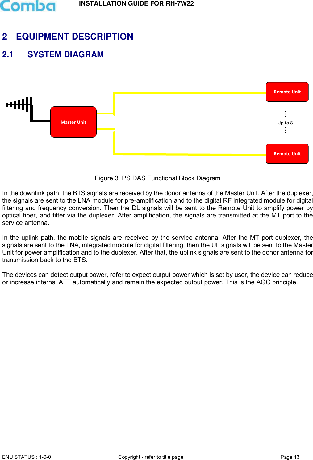
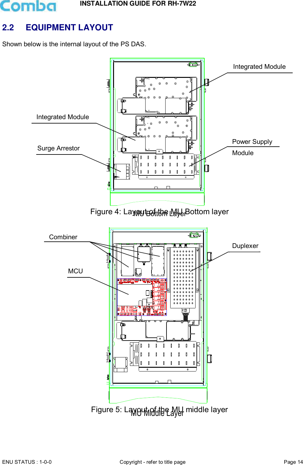
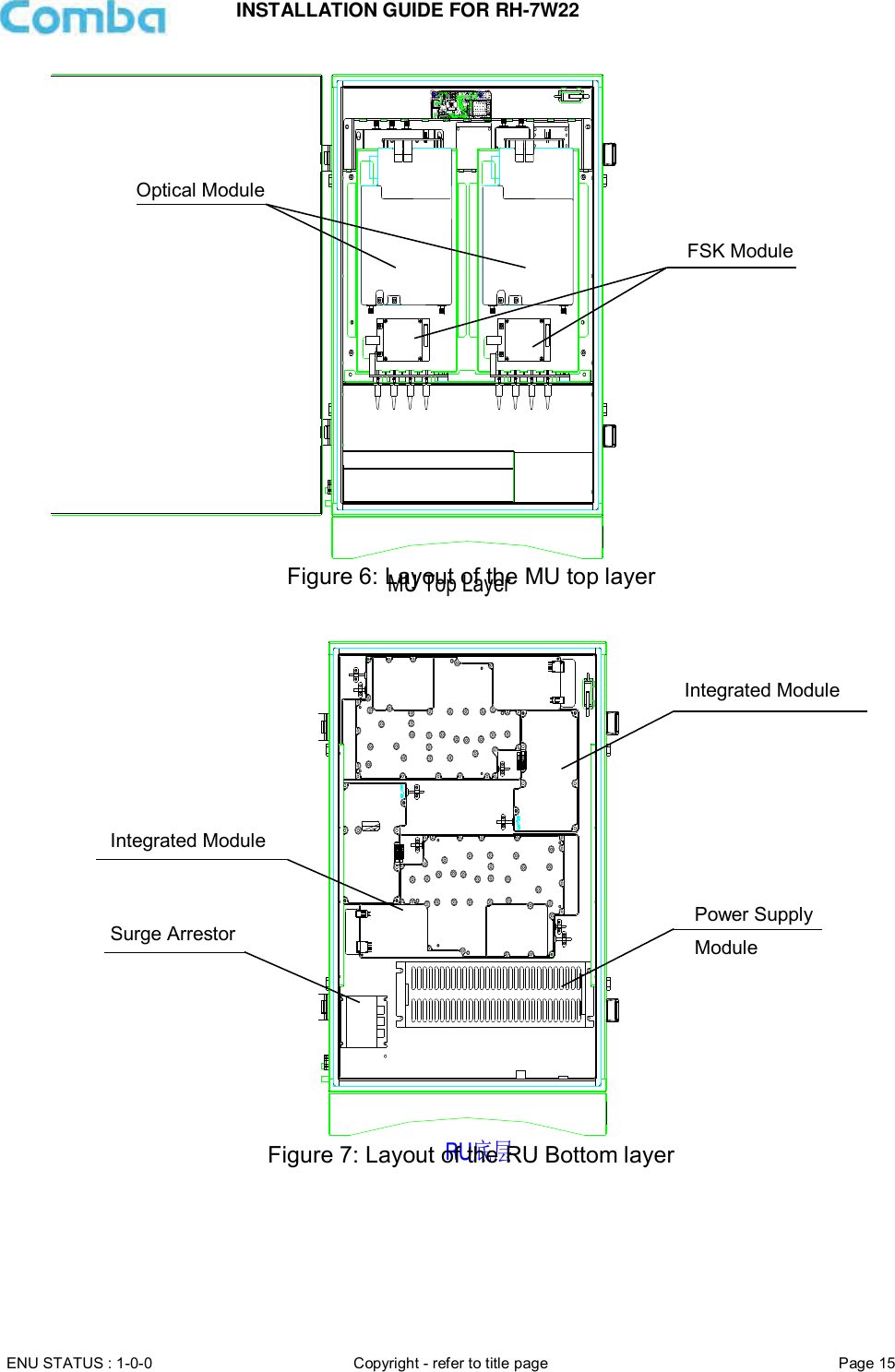
![INSTALLATION GUIDE FOR RH-7W22 ENU STATUS : 1-0-0 Copyright - refer to title page Page 3 0.1 CONTENTS Section Page 0.1 CONTENTS ................................................................................................................................. 3 0.2 INDEX TO FIGURES AND TABLES ......................................................................................... 5 0.3 HISTORY ..................................................................................................................................... 7 0.4 GLOSSARY OF TERMS ............................................................................................................ 8 0.5 SAFETY NOTICES AND ADMONISHMENTS ......................................................................... 9 1 GENERAL INFORMATION ...................................................................................................... 11 2 EQUIPMENT DESCRIPTION .................................................................................................. 13 2.1 SYSTEM DIAGRAM.................................................................................................................. 13 2.2 EQUIPMENT LAYOUT ............................................................................................................. 14 2.3 EQUIPMENT CONSTITUTION ................................................................................................ 16 3 INSTALLATION ......................................................................................................................... 17 3.1 WARNINGS AND ALERTS ...................................................................................................... 17 3.2 SITE PLANNING CONSIDERATIONS .................................................................................... 18 3.2.1 SITE PLANNING ....................................................................................................................... 18 3.2.2 INSTALLATION CHECKLIST................................................................................................... 19 3.3 INSTALLATION PROCEDURES ............................................................................................. 20 3.3.1 GOODS INWARDS INSPECTION........................................................................................... 20 3.3.2 TOOLS ....................................................................................................................................... 20 3.3.3 PREPARATION ......................................................................................................................... 20 3.3.4 WALL MOUNTING .................................................................................................................... 21 3.3.5 DRIP-LOOP ............................................................................................................................... 21 3.4 EQUIPMENT CONNECTORS ................................................................................................. 22 3.4.1 PS DAS CONNECTORS .......................................................................................................... 22 3.4.2 PS DAS LED Indicators ............................................................................................................ 24 3.4.3 GROUNDING CONNECTION .................................................................................................. 24 3.4.4 RF CABLE CONNECTION ....................................................................................................... 24 3.4.5 ETHERNET CONNECTION ..................................................................................................... 24 4 COMMISSIONING .................................................................................................................... 25 4.1 PRE-COMMISSIONING TASKS .............................................................................................. 25 4.2 COMMISSIONING PROCEDURE ........................................................................................... 26 5 WEB GUI ................................................................................................................................... 28 5.1 WEB GUI CONNECTION ......................................................................................................... 28 5.2 WEB GUI INTRODUCTION ..................................................................................................... 29 5.2.1 [TOPOLOGY][PARAMETER INFORMATION] ....................................................................... 29 5.2.2 [TOPOLOGY][FUNCTION] ....................................................................................................... 36 5.2.3 [TOPOLOGY][PROGRAM INFO] ............................................................................................. 41 5.2.4 [AUTO SETUP].......................................................................................................................... 41 5.2.5 [SYSTEM] .................................................................................................................................. 47 6 MAINTENANCE ........................................................................................................................ 51 7 APPENDICES ........................................................................................................................... 52 7.1 APPENDIX A: TOOLS .............................................................................................................. 52](https://usermanual.wiki/Comba-Telecom/RH-7W22-R/User-Guide-3786540-Page-3.png)
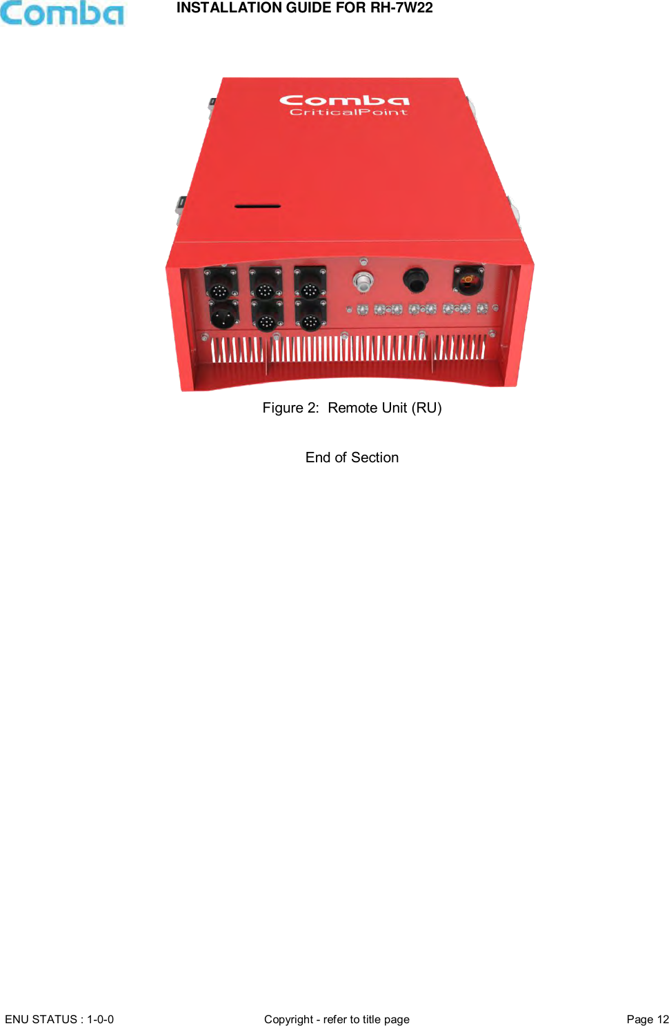
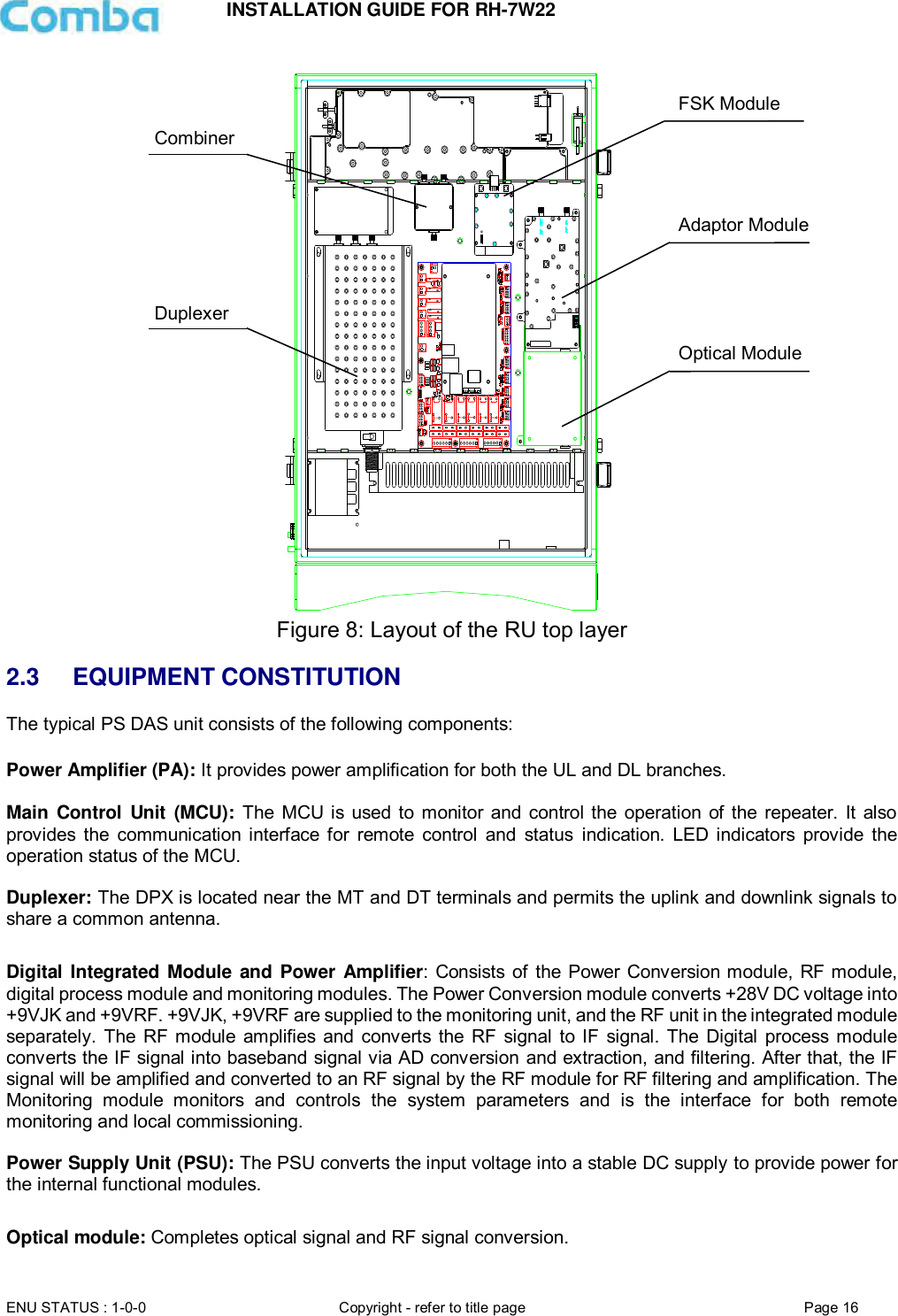
![INSTALLATION GUIDE FOR RH-7W22 ENU STATUS : 1-0-0 Copyright - refer to title page Page 5 0.2 INDEX TO FIGURES AND TABLES Figure 1: Master Unit (MU) ........................................................................................................................ 11 Figure 2: Remote Unit (RU) ....................................................................................................................... 12 Figure 3: PS DAS Functional Block Diagram ............................................................................................... 13 Figure 4: Layout of the MU Bottom layer ..................................................................................................... 14 Figure 5: Layout of the MU middle layer ...................................................................................................... 14 Figure 6: Layout of the MU top layer ........................................................................................................... 15 Figure 7: Layout of the RU Bottom layer ..................................................................................................... 15 Figure 8: Layout of the RU top layer............................................................................................................ 16 Figure 9: Mounting Rack Overview ............................................................................................................. 20 Figure 10: PS DAS Wall Mounting .............................................................................................................. 21 Figure 11: MU Equipment Connectors ........................................................................................................ 22 Figure 12: RU Equipment Connectors ......................................................................................................... 23 Figure 13: Commissioning Procedure ......................................................................................................... 26 Figure 14: Input IP Address ........................................................................................................................ 28 Figure 15: Input Domain Name ................................................................................................................... 28 Figure 16: Input User Name and Password ................................................................................................. 28 Figure 17: Web GUI Main Screen ............................................................................................................... 29 Figure 18: Overview Screen – MU .............................................................................................................. 30 Figure 19: Overview Screen – MU .............................................................................................................. 30 Figure 20: Overview Screen – RU ............................................................................................................... 31 Figure 21: Device alarm - MU ..................................................................................................................... 31 Figure 22: Device alarm - RU ...................................................................................................................... 32 Figure 23: 800MHz Screen - MU................................................................................................................. 32 Figure 24: 800MHz Screen - RU ................................................................................................................. 33 Figure 25: 700MHz Screen - MU................................................................................................................. 34 Figure 26: 700MHz Screen - RU ................................................................................................................. 34 Figure 27: Optical Information – MU............................................................................................................ 35 Figure 28: Optical Information – RU ............................................................................................................ 35 Figure 29: [Function] Screen ....................................................................................................................... 36 Figure 30: Function – Device Info ............................................................................................................... 36 Figure 31: Function – Import & Export ......................................................................................................... 37 Figure 32: Function – Summary .................................................................................................................. 37 Figure 33: Function – Comm. Setting .......................................................................................................... 38 Figure 34: Function –Reset ......................................................................................................................... 38 Figure 35: Function – Firmware Upgrade .................................................................................................... 39 Figure 36: Function – Log ........................................................................................................................... 39 Figure 37: Function – Alarm Setting ............................................................................................................ 40 Figure 38: Function – License ..................................................................................................................... 40 Figure 39: Program Information .................................................................................................................. 41 Figure 40: Commissioning Procedure – Start .............................................................................................. 42 Figure 41: Commissioning Procedure – Scan ............................................................................................. 43 Figure 42: Commissioning Procedure – Isolation Detection ......................................................................... 44 Figure 43: Device Information Setting ......................................................................................................... 45 Figure 44: MU Parameter Setting ................................................................................................................ 46 Figure 45: RU Parameter Setting ................................................................................................................ 46 Figure 46: Finish ......................................................................................................................................... 47 Figure 47: System – Import & Export .......................................................................................................... 47 Figure 48: System – Summary .................................................................................................................... 48 Figure 49: System – Scan ........................................................................................................................... 48 Figure 50: System – Remove ...................................................................................................................... 48 Figure 51: System – Firmware .................................................................................................................... 49 Figure 52: System – Log ............................................................................................................................. 49 Figure 53: System – Isolation...................................................................................................................... 49](https://usermanual.wiki/Comba-Telecom/RH-7W22-R/User-Guide-3786540-Page-5.png)
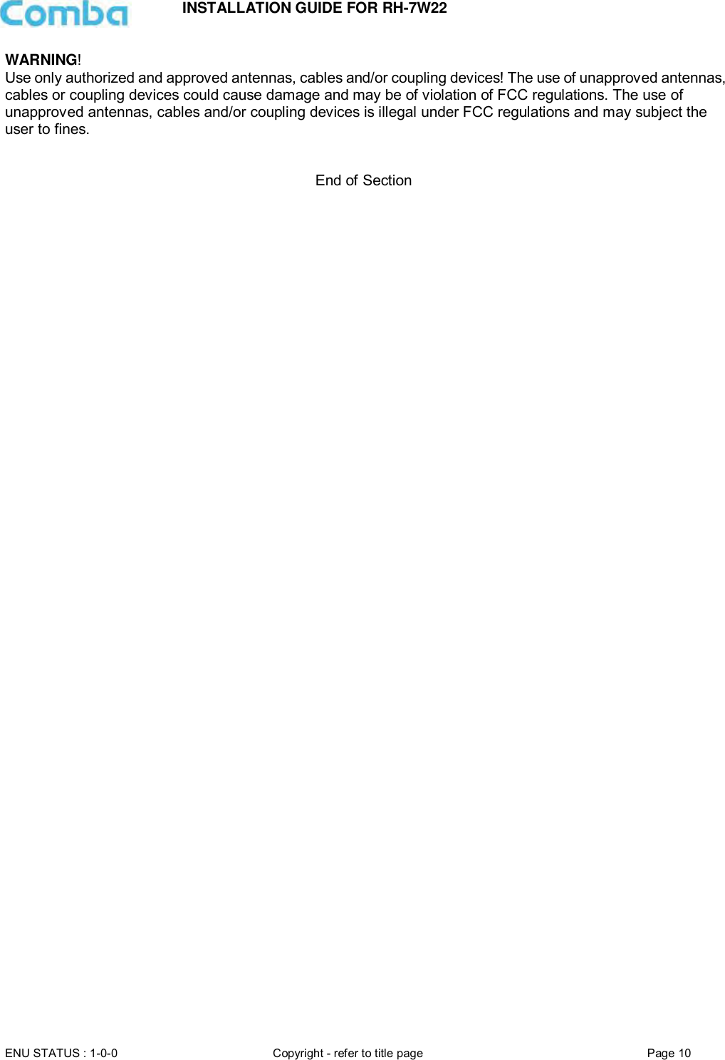
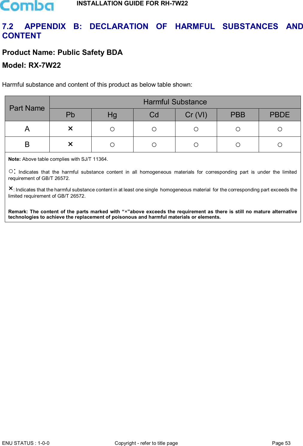
![INSTALLATION GUIDE FOR RH-7W22 ENU STATUS : 1-0-0 Copyright - refer to title page Page 28 5 WEB GUI The PS DAS can be monitored and controlled via the WEB GUI; use the following guide to finish system parameter setting and commissioning. 5.1 WEB GUI CONNECTION Step 1: Connect the OMT port to the PC RJ45 port with the supplied RJ45 cable to set up a physical connection. Step 2: Open a browser (suggested Firefox browser, display resolution is 1024×768), input Web GUI IP address: 192.168.8.101, click [Enter]. NOTE: DHCP and DNS are also available to login to the Web GUI. The domain name is: www.combaomt.com. Figure 14: Input IP Address Figure 15: Input Domain Name Step 3: Input User Name: admin; Password (default password: admin). Click [Log in]. Figure 16: Input User Name and Password](https://usermanual.wiki/Comba-Telecom/RH-7W22-R/User-Guide-3786540-Page-28.png)
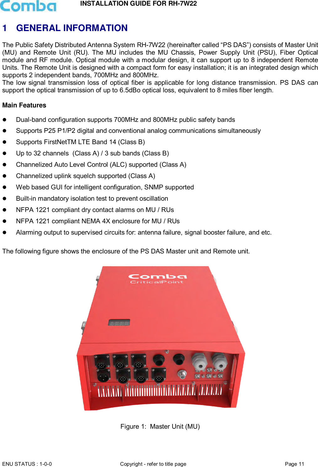
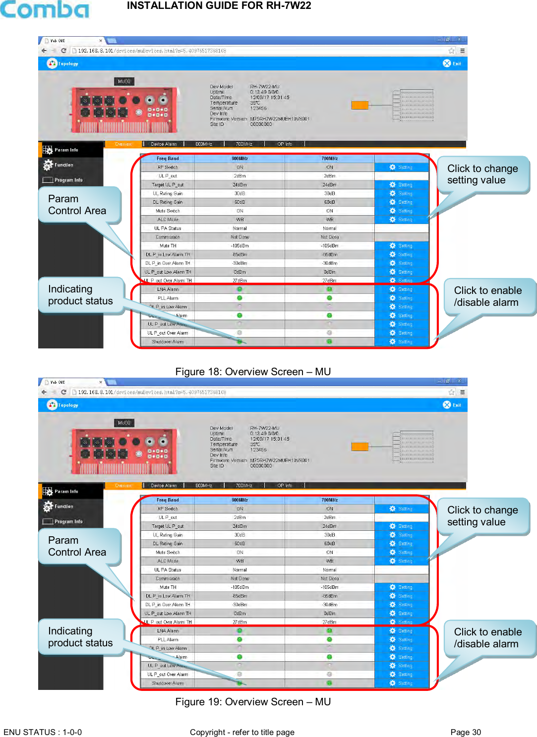
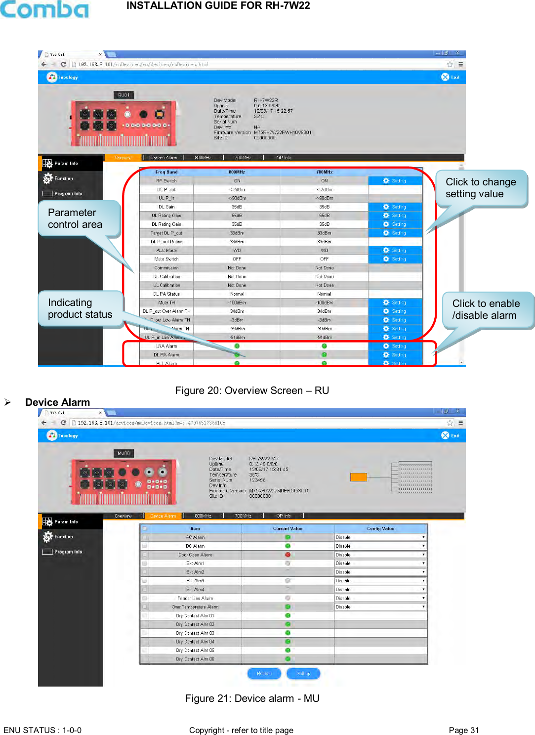
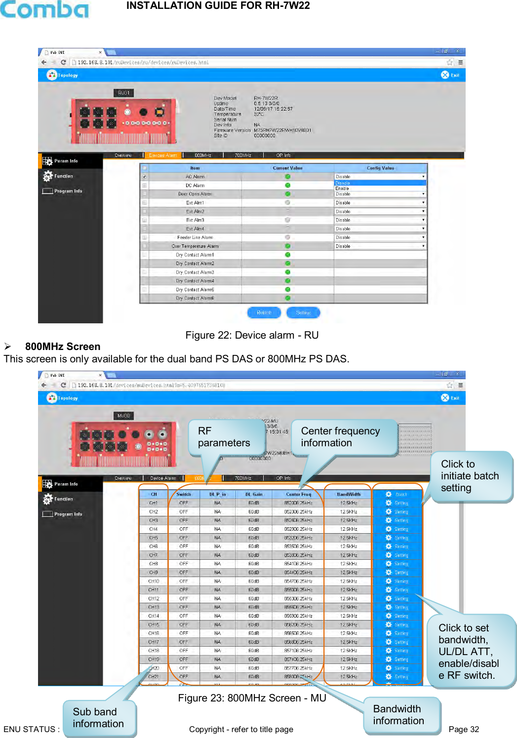
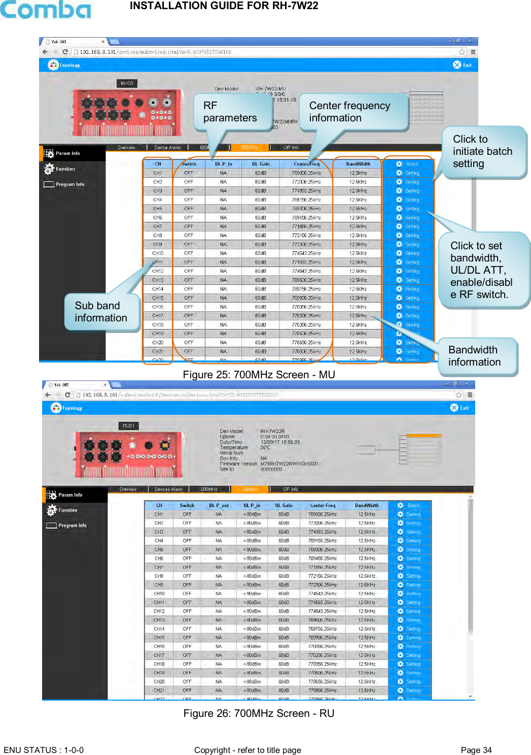
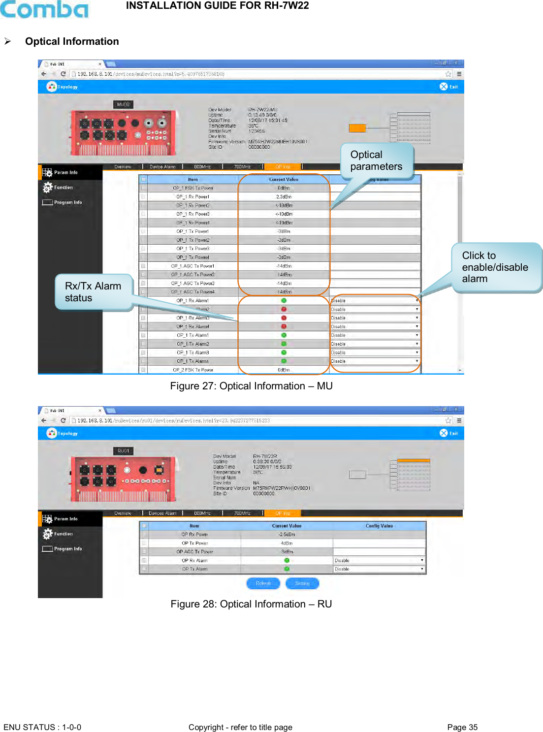
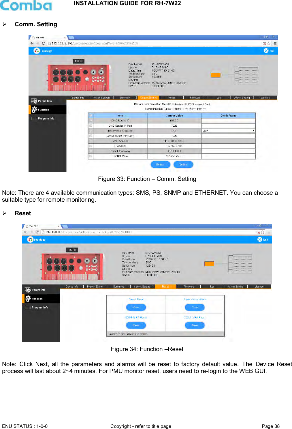
![INSTALLATION GUIDE FOR RH-7W22 ENU STATUS : 1-0-0 Copyright - refer to title page Page 29 5.2 WEB GUI INTRODUCTION After log in, the Web GUI main screen will appear. Figure 17: Web GUI Main Screen On Comba Web GUI Home Screen, there are three Menu bars: [Topology], [Auto Setup] and [System]. 5.2.1 [TOPOLOGY][PARAMETER INFORMATION] The [Topology] Screen shows the equipment status, such as setting status, alarm information, etc. Overview Screen Indicates RU quantities](https://usermanual.wiki/Comba-Telecom/RH-7W22-R/User-Guide-3786540-Page-29.png)
![INSTALLATION GUIDE FOR RH-7W22 ENU STATUS : 1-0-0 Copyright - refer to title page Page 36 5.2.2 [TOPOLOGY][FUNCTION] Other parameters can be configured on the [Function] Screen. There are nine function bars list on the middle of the [Function] Screen. Figure 29: [Function] Screen Device Info Figure 30: Function – Device Info Click here to get PC time. Input device information. Management menu, click to enter each page for parameters setting.](https://usermanual.wiki/Comba-Telecom/RH-7W22-R/User-Guide-3786540-Page-36.png)
![INSTALLATION GUIDE FOR RH-7W22 ENU STATUS : 1-0-0 Copyright - refer to title page Page 39 Firmware There are two functions on the [Firmware] bar: [upgrade] and [swap]. [Upgrade] is used to upgrade software, and [Swap] is to replace the current firmware version with the previous one. Follow the steps shown below figure to upgrade the firmware. Figure 35: Function – Firmware Upgrade Log Figure 36: Function – Log Step 1: Click to select the file for upgrading. Step 2: Click to finish the software upgrading. Click to swap the firmware to the previous version](https://usermanual.wiki/Comba-Telecom/RH-7W22-R/User-Guide-3786540-Page-39.png)
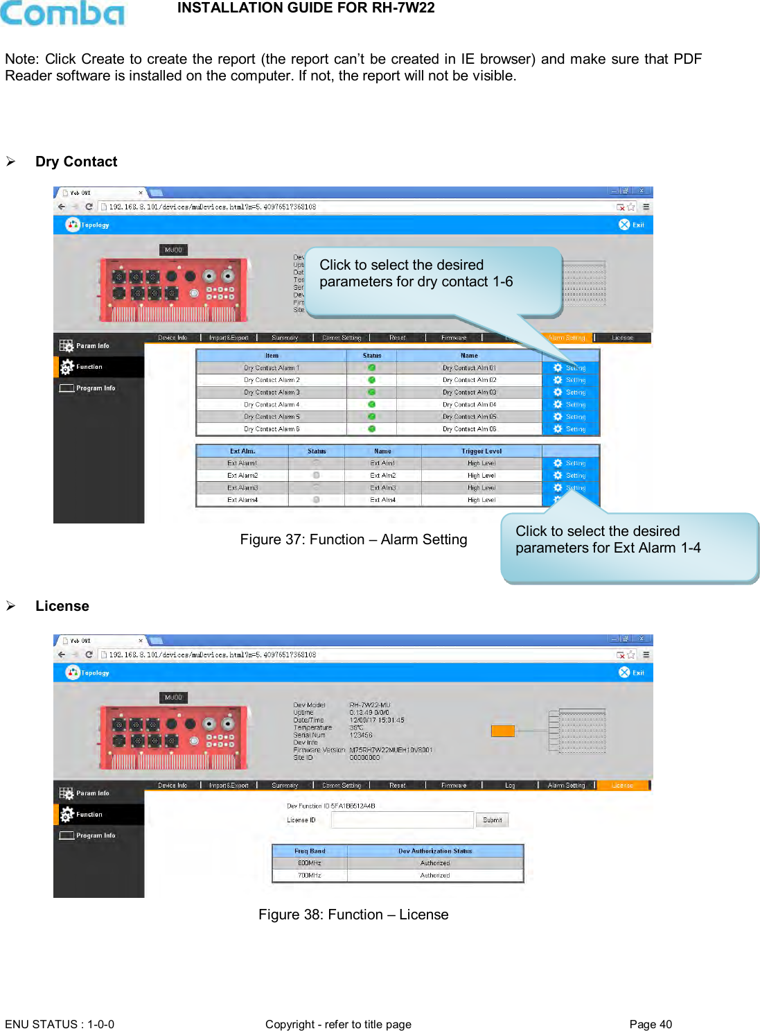
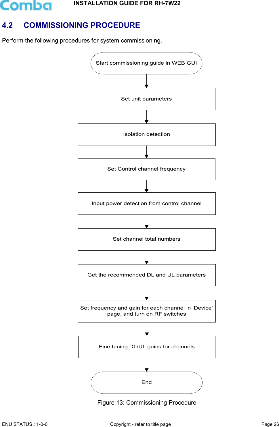
![INSTALLATION GUIDE FOR RH-7W22 ENU STATUS : 1-0-0 Copyright - refer to title page Page 41 For the CriticalPoint DAS, users are able to switch the configuration anytime by changing the license in the WEBOMT. There are 3 difference licenses: 700MHz single band license, 800MHz single band license and 700MHz/800MHz dual band license. Both 700MHz and 800MHz single band licenses are provided with a single band unit. Users can switch between 700MHz configuration and 800MHz configuration. To upgrade from single band to dual band, users need to purchase the dual band upgrade license. If the equipment is in dual band originally, no license will be provided, because the equipment already comes with dual band activated. For more information please refer to appendix B for the license switch guide. 5.2.3 [TOPOLOGY][PROGRAM INFO] This page is for factory setting only. Figure 39: Program Information 5.2.4 [AUTO SETUP] To complete the installation and commissioning, users need to follow the steps below. Step 1: Click the Menu bar [Auto Setup] on home screen, a work flow will be displayed.](https://usermanual.wiki/Comba-Telecom/RH-7W22-R/User-Guide-3786540-Page-41.png)
![INSTALLATION GUIDE FOR RH-7W22 ENU STATUS : 1-0-0 Copyright - refer to title page Page 42 Figure 40: Commissioning Procedure – Start Step 2: Click [Start] to start the process.](https://usermanual.wiki/Comba-Telecom/RH-7W22-R/User-Guide-3786540-Page-42.png)
![INSTALLATION GUIDE FOR RH-7W22 ENU STATUS : 1-0-0 Copyright - refer to title page Page 43 Figure 41: Commissioning Procedure – Scan NOTE: Make sure the device is connected with appropriate donor and service antennas before proceeding to step 3. Step 3: Click [Next] to enter to Isolation Detection Screen.](https://usermanual.wiki/Comba-Telecom/RH-7W22-R/User-Guide-3786540-Page-43.png)
![INSTALLATION GUIDE FOR RH-7W22 ENU STATUS : 1-0-0 Copyright - refer to title page Page 44 Figure 42: Commissioning Procedure – Isolation Detection Step 4: Click [Next] to set the site information.](https://usermanual.wiki/Comba-Telecom/RH-7W22-R/User-Guide-3786540-Page-44.png)
![INSTALLATION GUIDE FOR RH-7W22 ENU STATUS : 1-0-0 Copyright - refer to title page Page 45 Figure 43: Device Information Setting It is mainly used to record device location and Date/Time provides a time reference. Clicking the Config Value of Date/Time will update the Date/Time automatically. Step 5: Click [MU Setup] to MU parameter setting.](https://usermanual.wiki/Comba-Telecom/RH-7W22-R/User-Guide-3786540-Page-45.png)
![INSTALLATION GUIDE FOR RH-7W22 ENU STATUS : 1-0-0 Copyright - refer to title page Page 46 Figure 44: MU Parameter Setting Step 6: Click [Next] to RU parameter setting. Figure 45: RU Parameter Setting](https://usermanual.wiki/Comba-Telecom/RH-7W22-R/User-Guide-3786540-Page-46.png)
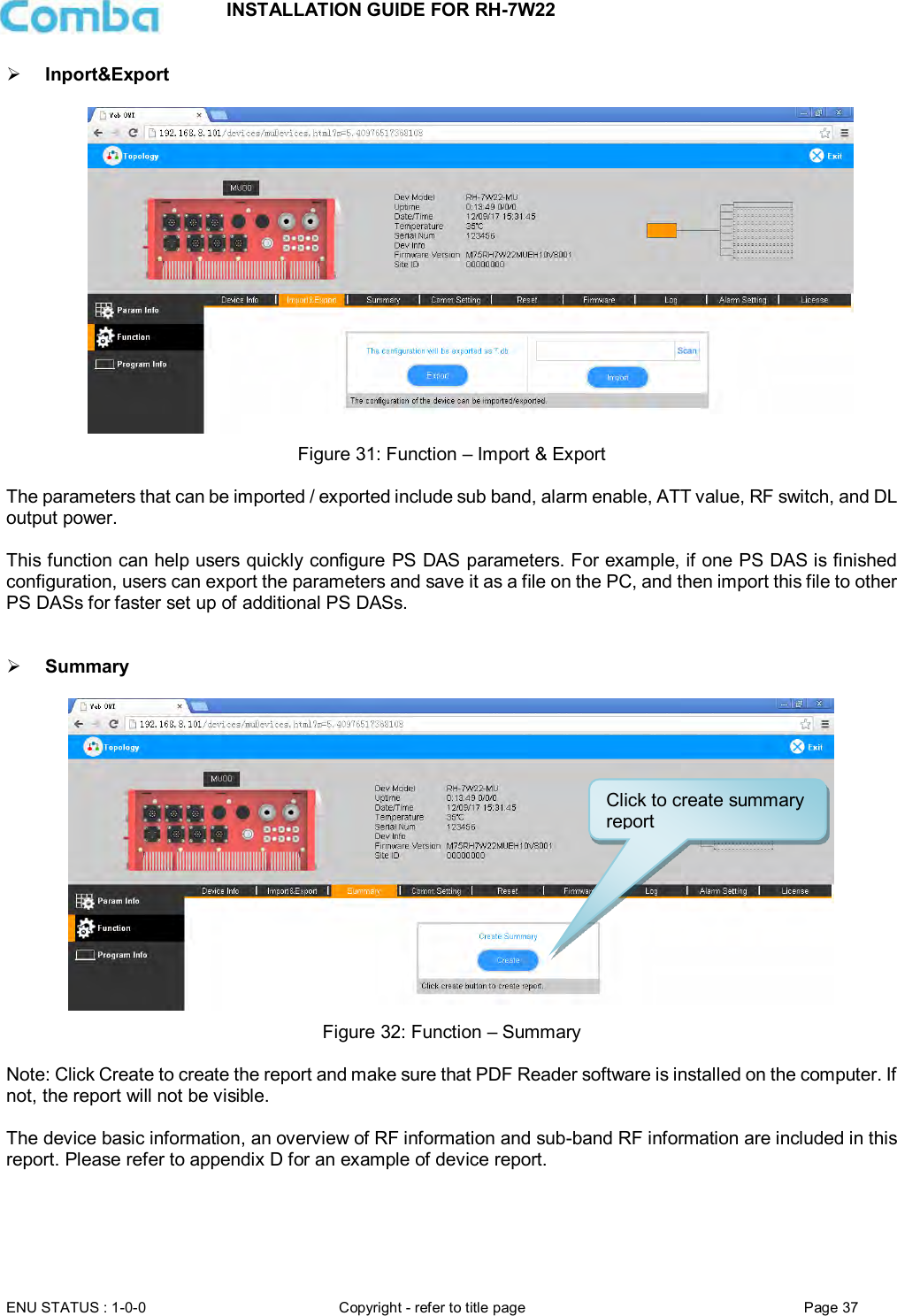
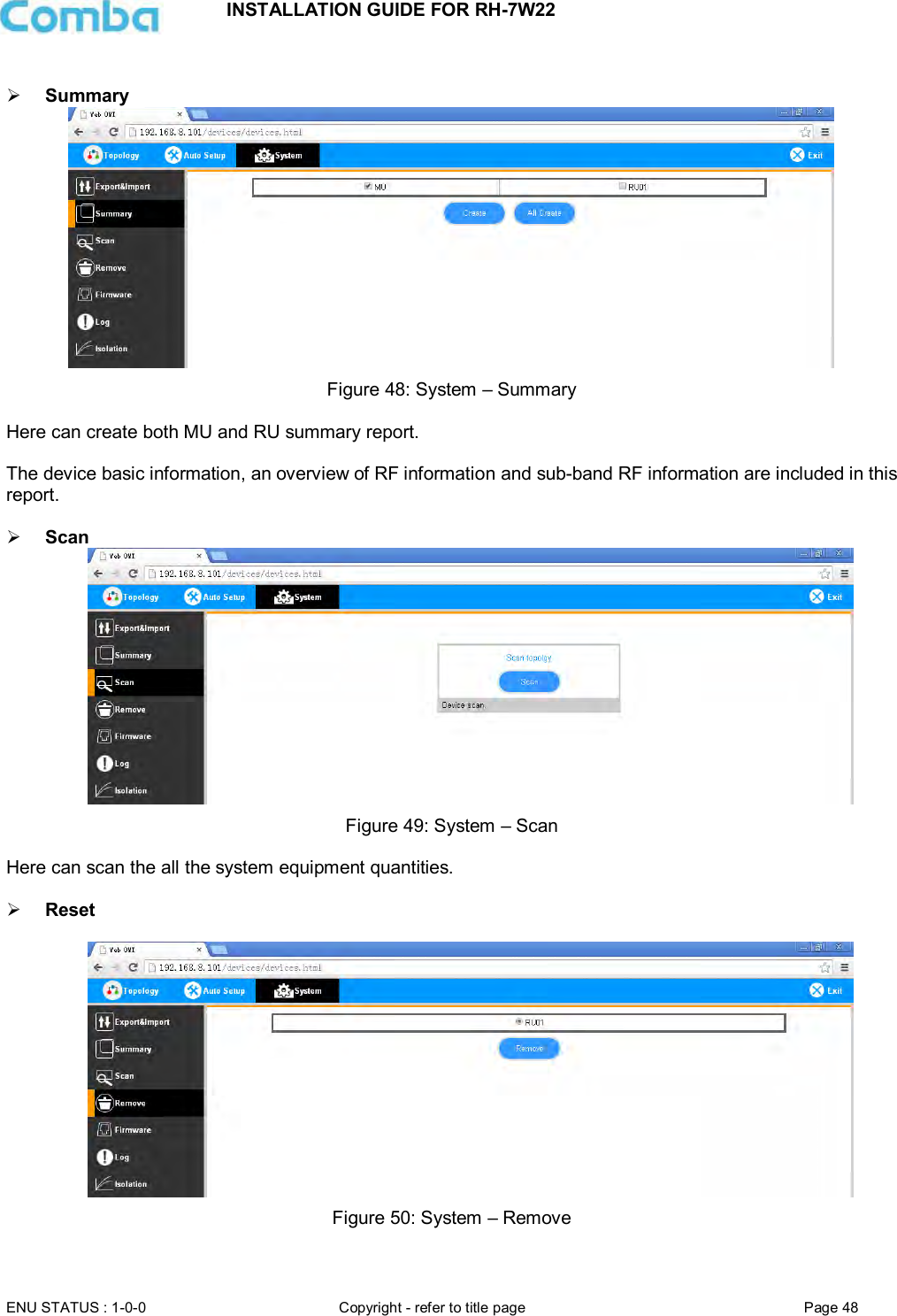
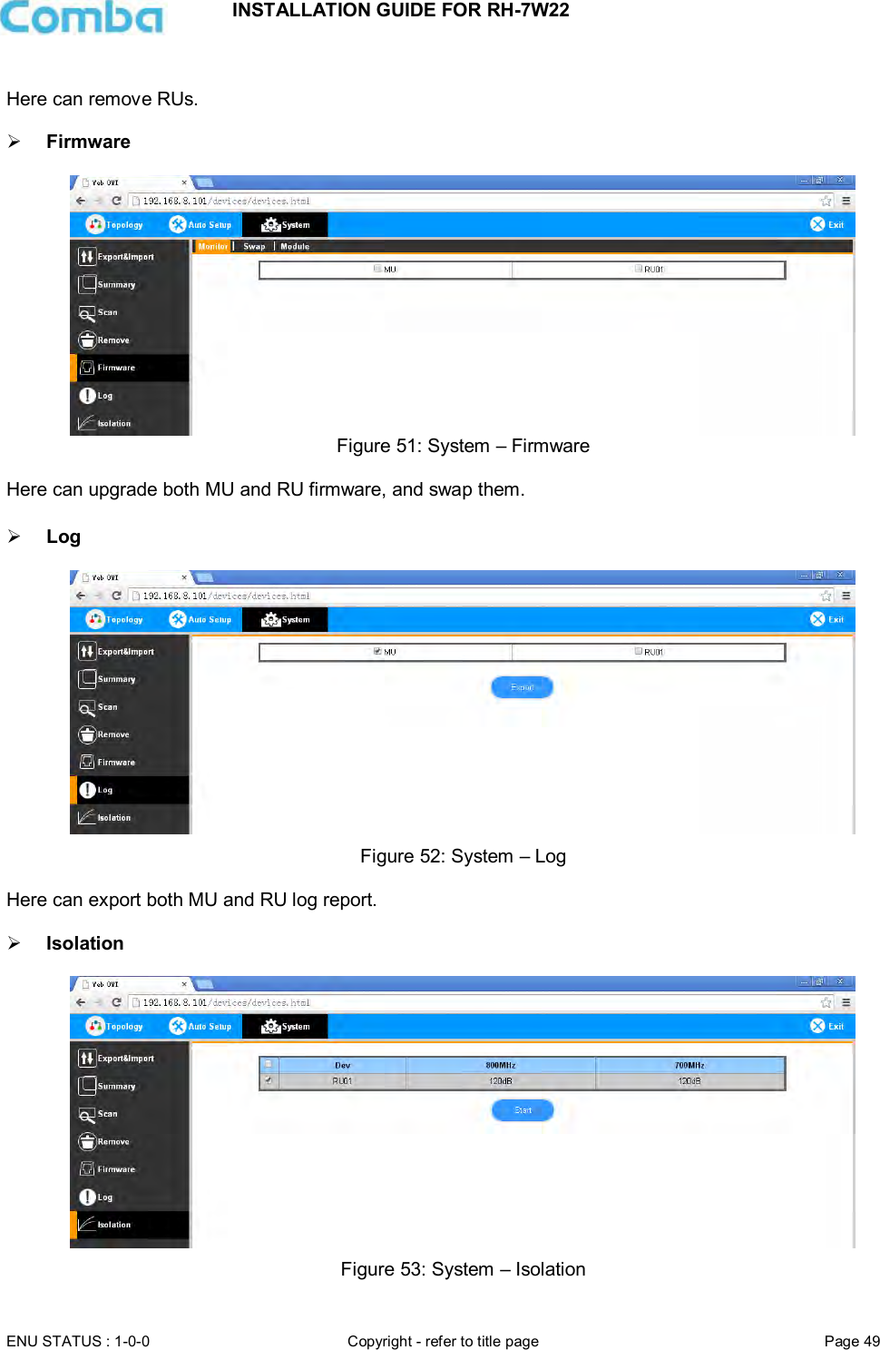
![INSTALLATION GUIDE FOR RH-7W22 ENU STATUS : 1-0-0 Copyright - refer to title page Page 47 Step 7: Select [Finish] and click [OK] to finish commissioning. Figure 46: Finish 5.2.5 [SYSTEM] Inport&Export Figure 47: System – Import & Export Here can be imported / exported both MU and RU parameters. The parameters that can be imported / exported include sub band, alarm enable, ATT value, RF switch, and DL output power.](https://usermanual.wiki/Comba-Telecom/RH-7W22-R/User-Guide-3786540-Page-47.png)
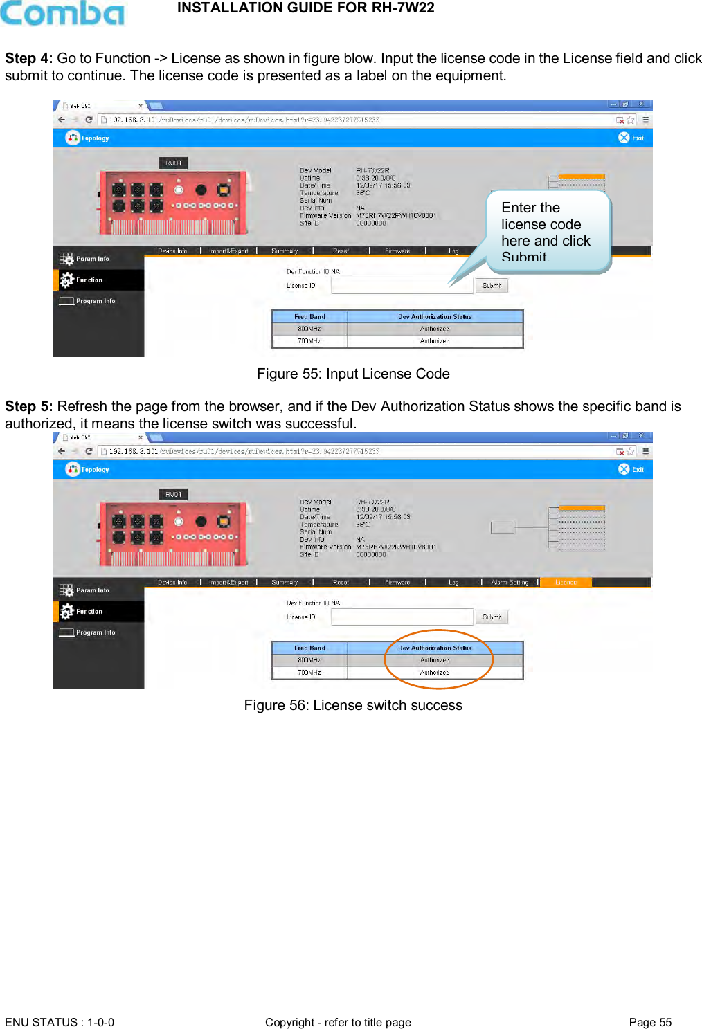
![INSTALLATION GUIDE FOR RH-7W22 ENU STATUS : 1-0-0 Copyright - refer to title page Page 54 7.3 APPENDIX C: LICENSE SWITCH QUICK GUIDE For CriticalPoint DAS, users are able to switch the configuration anytime by changing the license in the WEBOMT. There are 3 difference licenses: 700MHz single band license, 800MHz single band license and 700MHz/800MHz dual band license. Both 700MHz and 800MHz single band licenses are provided with a single band unit. Users can switch between 700MHz configuration and 800MHz configuration. To upgrade from single band to dual band configurations, users need to purchase the dual band upgrade license.. If the equipment is in dual band originally, no license will be provided, because the equipment already comes with dual band activated. Please follow the steps to switch configuration by license: Step 1: Connect the unit “OMT port” to a laptop with an Ethernet cable. Step 2: Wait approximately 1 minute until the IP address is established. Open the browser (Firefox is recommended), login to WEBGUI with: www.combaomt.com or 192.168.8.101. Step 3: Input User Name: admin; Password: (default: admin). Click [Log in]. Figure 54: Input User Name and Password](https://usermanual.wiki/Comba-Telecom/RH-7W22-R/User-Guide-3786540-Page-54.png)