Comba Telecom RS-5180 In-Building RF Distribution System User Manual file
Comba Telecom Ltd. In-Building RF Distribution System file
UserManual.wiki
>
Comba Telecom
>
RS 5180 User Manual
User Manual
Navigation menu
Upload a User Manual
Namespaces
Wiki Guide
HTML
PDF
Info
Views
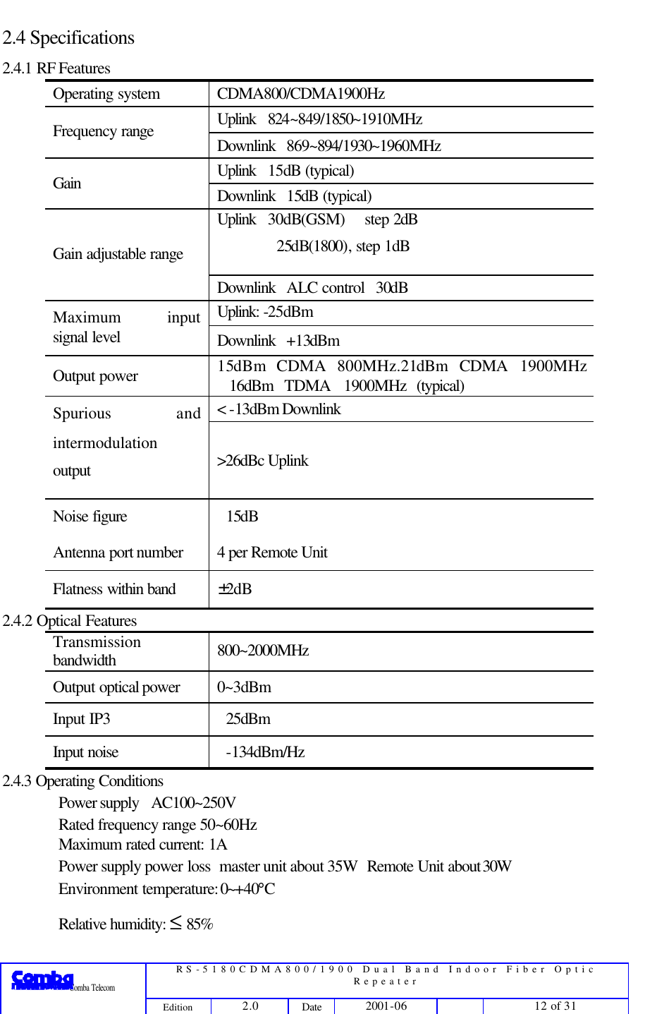
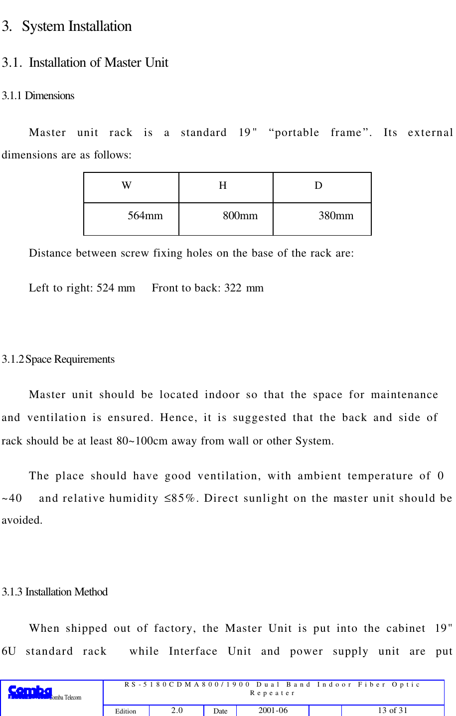
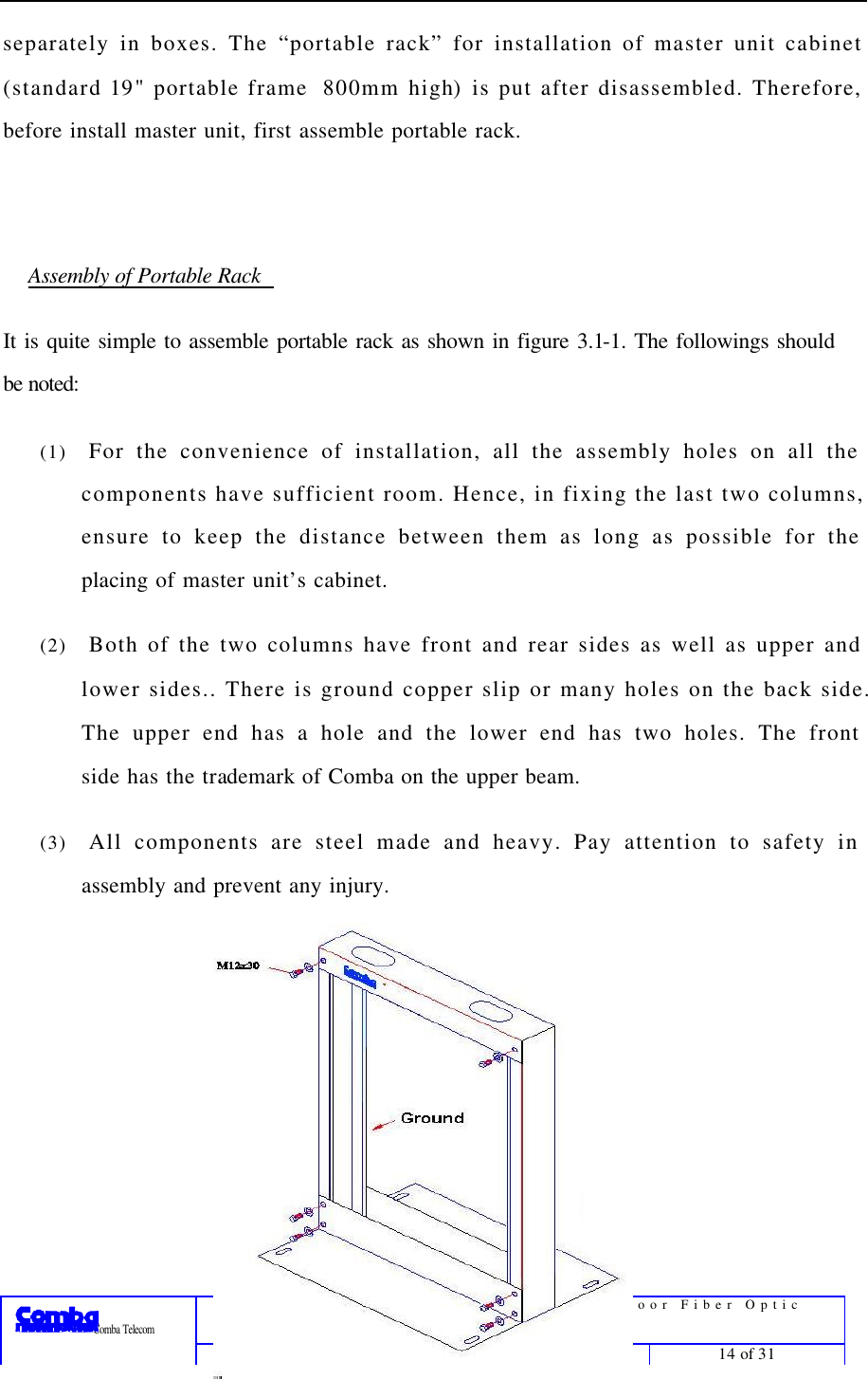
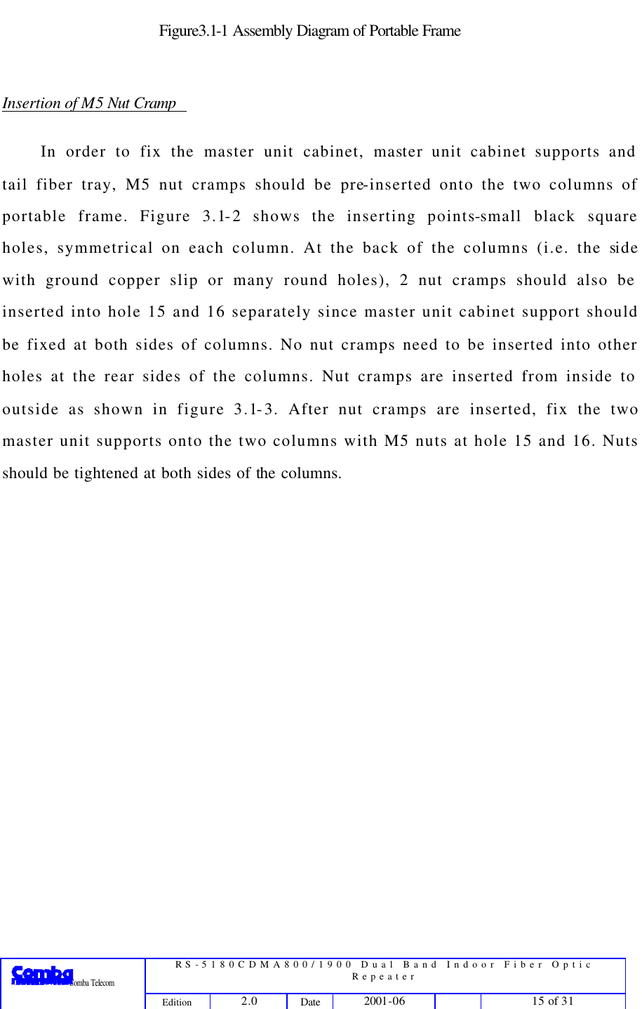
User Manual
Discussion / Help
Navigation