Comba Telecom RX-7W22B 700/800MHz Public Safety Bi-directional Amplifier User Manual RX 7W22 B Manual v1
Comba Telecom Ltd. 700/800MHz Public Safety Bi-directional Amplifier RX 7W22 B Manual v1
UserManual.wiki
>
Comba Telecom
>
RX 7W22B User Manual
RX-7W22-B Manual v1
Navigation menu
Upload a User Manual
Namespaces
Wiki Guide
HTML
PDF
Info
Views
User Manual
Discussion / Help
Navigation
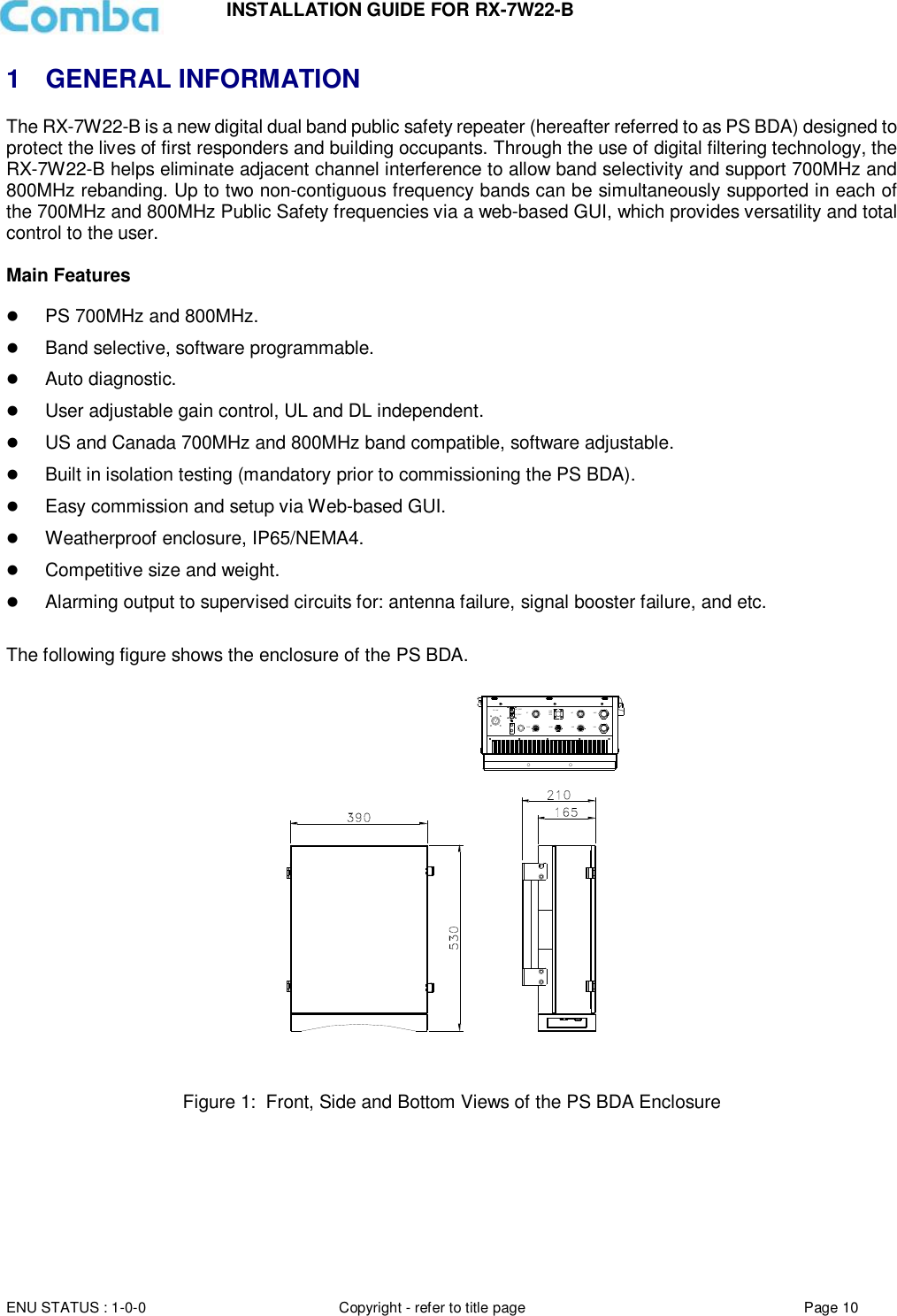
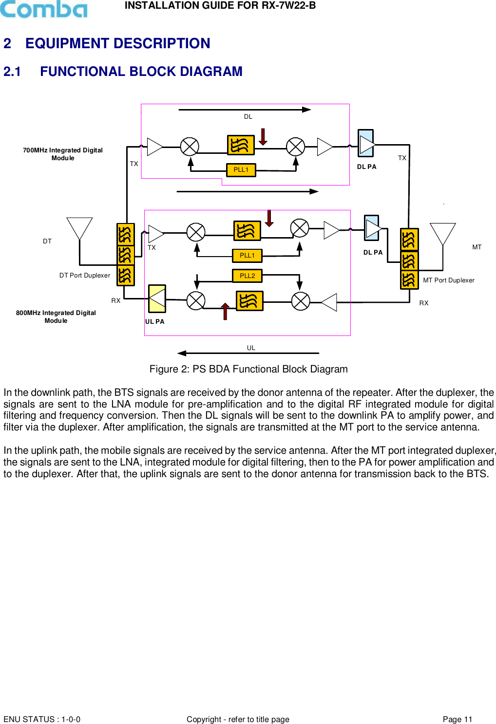
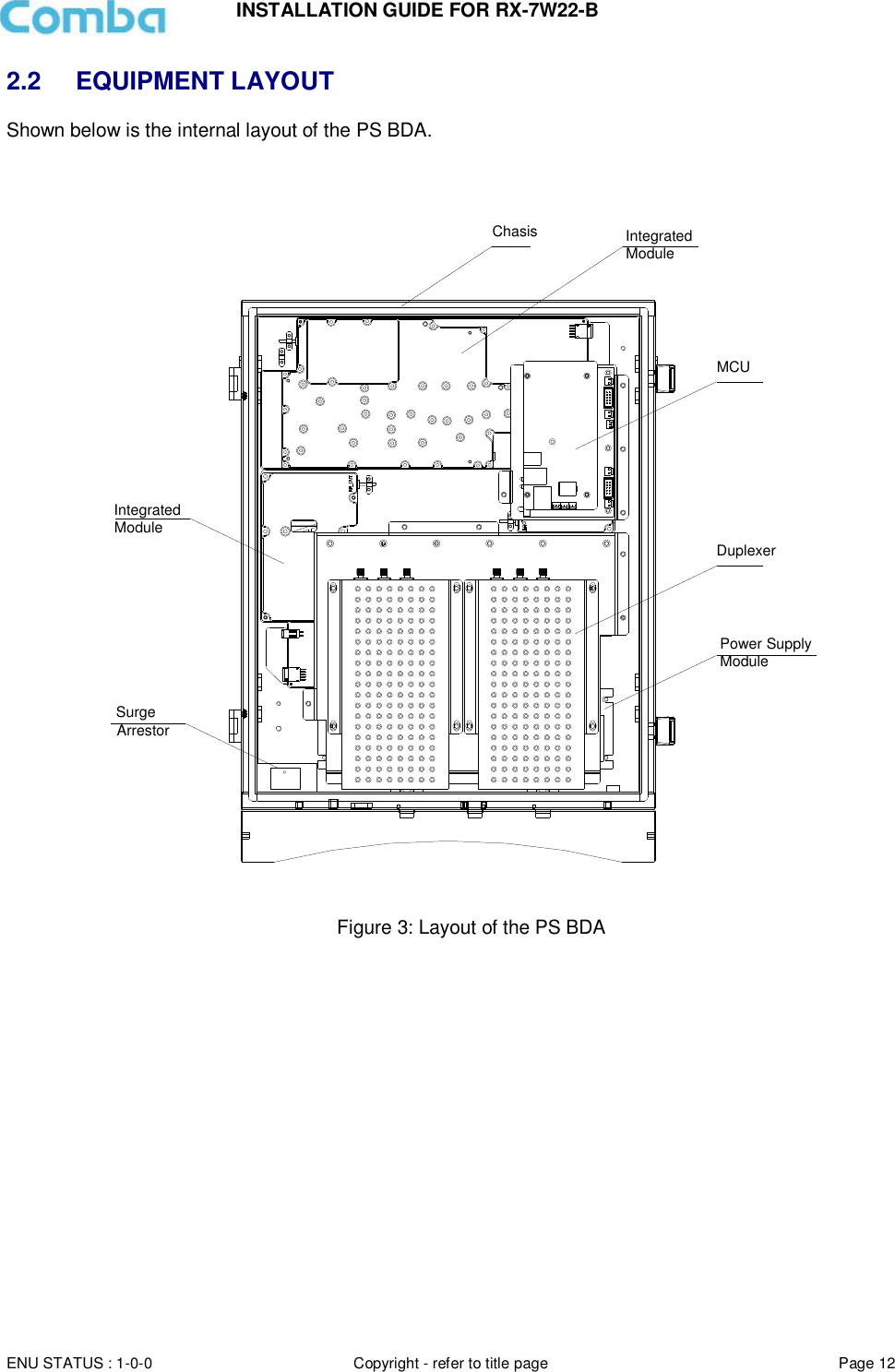
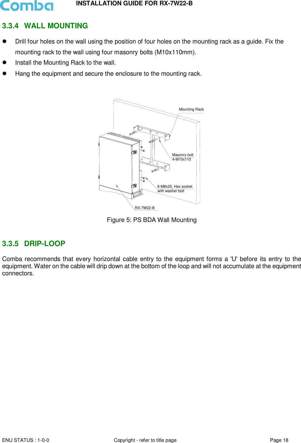
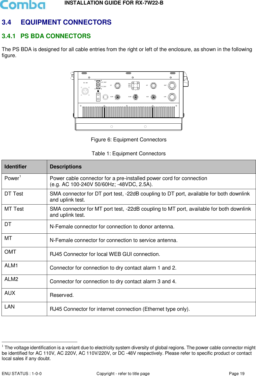
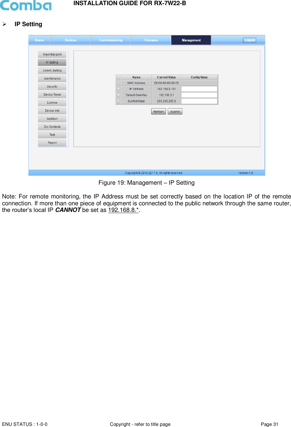
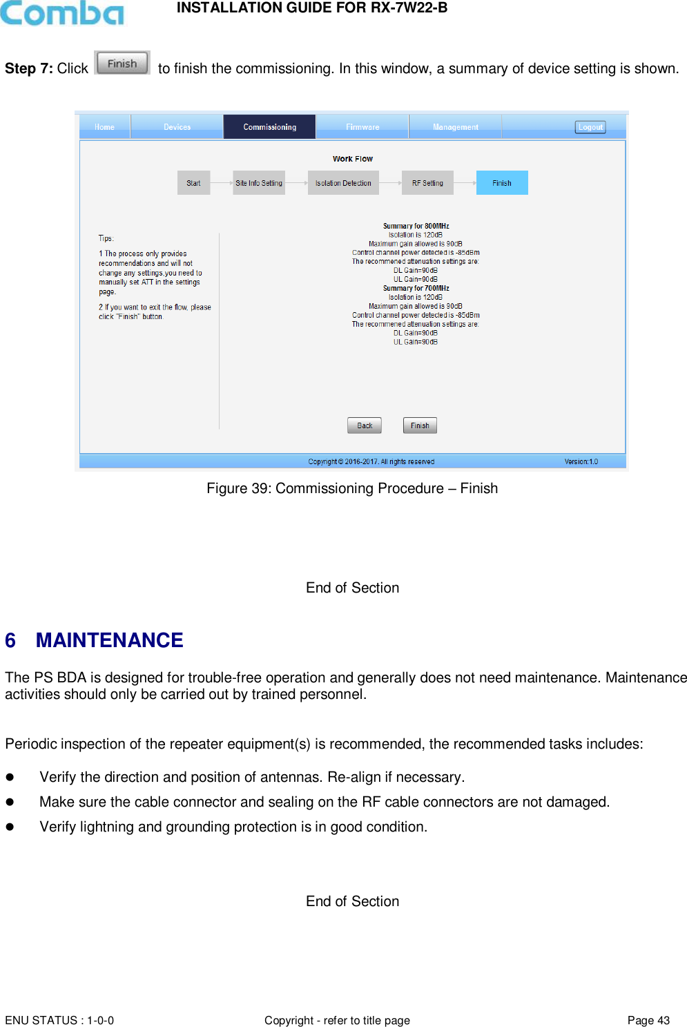
![INSTALLATION GUIDE FOR RX-7W22-B ENU STATUS : 1-0-0 Copyright - refer to title page Page 4 0.1 CONTENTS Section Page 0.1 CONTENTS ................................................................................................................................. 4 0.2 INDEX TO FIGURES AND TABLES ......................................................................................... 6 0.3 HISTORY ..................................................................................................................................... 7 0.4 GLOSSARY OF TERMS ............................................................................................................ 8 0.5 SAFETY NOTICES AND ADMONISHMENTS ......................................................................... 9 1 GENERAL INFORMATION ...................................................................................................... 10 2 EQUIPMENT DESCRIPTION .................................................................................................. 11 2.1 FUNCTIONAL BLOCK DIAGRAM ........................................................................................... 11 2.2 EQUIPMENT LAYOUT ............................................................................................................. 12 2.3 EQUIPMENT CONSTITUTION ................................................................................................ 13 3 INSTALLATION ......................................................................................................................... 14 3.1 WARNINGS AND ALERTS ...................................................................................................... 14 3.2 SITE PLANNING CONSIDERATIONS .................................................................................... 15 3.2.1 SITE PLANNING ....................................................................................................................... 15 3.2.2 INSTALLATION CHECKLIST................................................................................................... 16 3.3 INSTALLATION PROCEDURES ............................................................................................. 17 3.3.1 GOODS INWARDS INSPECTION........................................................................................... 17 3.3.2 TOOLS ....................................................................................................................................... 17 3.3.3 PREPARATION ......................................................................................................................... 17 3.3.4 WALL MOUNTING .................................................................................................................... 18 3.3.5 DRIP-LOOP ............................................................................................................................... 18 3.4 EQUIPMENT CONNECTORS ................................................................................................. 19 3.4.1 PS BDA CONNECTORS .......................................................................................................... 19 3.4.2 PS BDA LED Indicators ............................................................................................................ 20 3.4.3 GROUNDING CONNECTION .................................................................................................. 20 3.4.4 RF CABLE CONNECTION ....................................................................................................... 20 3.4.5 ETHERNET CONNECTION ..................................................................................................... 20 3.4.6 DRY CONTACT CABLE CONNECTION ................................................................................ 21 4 COMMISSIONING .................................................................................................................... 22 4.1 PRE-COMMISSIONING TASKS .............................................................................................. 22 4.2 COMMISSIONING PROCEDURE ........................................................................................... 23 5 WEB GUI ................................................................................................................................... 25 5.1 WEB GUI CONNECTION ......................................................................................................... 25 5.2 WEB GUI INTRODUCTION ..................................................................................................... 26 5.2.1 [DEVICES] ................................................................................................................................. 26 5.2.2 [COMMISSIONING] .................................................................................................................. 28 5.2.3 [FIRMWARE] ............................................................................................................................. 28 5.2.4 [MANAGEMENT]....................................................................................................................... 29 5.3 COMMISSIONING PROCEDURE ........................................................................................... 39 6 MAINTENANCE ........................................................................................................................ 43 7 APPENDICES ........................................................................................................................... 44 7.1 APPENDIX A: TOOLS .............................................................................................................. 44 7.2 APPENDIX B: DECLARATION OF HARMFUL SUBSTANCES AND CONTENT ............... 45](https://usermanual.wiki/Comba-Telecom/RX-7W22B/User-Guide-3480240-Page-3.png)
![INSTALLATION GUIDE FOR RX-7W22-B ENU STATUS : 1-0-0 Copyright - refer to title page Page 6 0.2 INDEX TO FIGURES AND TABLES Figure 1: Front, Side and Bottom Views of the PS BDA Enclosure ............................................................. 10 Figure 2: PS BDA Functional Block Diagram ............................................................................................... 11 Figure 3: Layout of the PS BDA .................................................................................................................. 12 Figure 4: Mounting Rack Overview ............................................................................................................. 17 Figure 5: PS BDA Wall Mounting ................................................................................................................ 18 Figure 6: Equipment Connectors................................................................................................................. 19 Figure 7: Commissioning Procedure ........................................................................................................... 23 Figure 8: Input IP Address .......................................................................................................................... 25 Figure 9: Input Domain Name ..................................................................................................................... 25 Figure 10: Input User Name and Password ................................................................................................. 25 Figure 11: Web GUI Main Screen ............................................................................................................... 26 Figure 12: Overview Screen........................................................................................................................ 27 Figure 13: 800MHz Screen ......................................................................................................................... 27 Figure 14: 700MHz Screen ......................................................................................................................... 28 Figure 15: [Commissioning] Screen ............................................................................................................ 28 Figure 16: [Firmware] Screen – MCU Firmware Upgrade ............................................................................ 29 Figure 17: [Management] Screen ................................................................................................................ 29 Figure 18: Management – Import & Export .................................................................................................. 30 Figure 19: Management – IP Setting ........................................................................................................... 31 Figure 20: Management – Comm. Setting ................................................................................................... 32 Figure 21: New Site Report is for easy monitoring set up ............................................................................ 33 Figure 22: Management – Security ............................................................................................................. 33 Figure 23: Modify Password........................................................................................................................ 34 Figure 24: Management – Device Reset ..................................................................................................... 34 Figure 25: Management – License .............................................................................................................. 35 Figure 26: Management – Device Info ........................................................................................................ 36 Figure 27: Management – Isolation ............................................................................................................. 36 Figure 28: Management – Dry Contact ....................................................................................................... 37 Figure 29: Management – Test ................................................................................................................... 37 Figure 30: Management – Report ............................................................................................................... 38 Figure 31: Commissioning Procedure – Start .............................................................................................. 39 Figure 32: Commissioning Procedure – Site Info. Setting ............................................................................ 39 Figure 33: Device Information Setting ......................................................................................................... 40 Figure 34: Commissioning Procedure – Isolation Detection ......................................................................... 40 Figure 35: Commissioning Procedure – Isolation Detection Confirm ............................................................ 41 Figure 36: Commissioning Procedure – Isolation Detection Failed .............................................................. 41 Figure 37: Commissioning Procedure – Isolation Detection Finish ............................................................... 42 Figure 38: Commissioning Procedure – Target Output Setting .................................................................... 42 Figure 39: Commissioning Procedure – Finish ............................................................................................ 43 Figure 40: Input User Name and Password ................................................................................................. 46 Figure 41: Input License Code .................................................................................................................... 47 Figure 42: License switch success .............................................................................................................. 47 Figure 43: Alarm list .................................................................................................................................... 48 Figure 44: Reset PA ................................................................................................................................... 49 Table 1: Equipment Connectors .................................................................................................................. 19 Table 2: LED Indicators .............................................................................................................................. 20 Table 3: Pin Definition of Dry Contact Cable ............................................................................................... 21 Table 4: Commissioning Task Explanation .................................................................................................. 24](https://usermanual.wiki/Comba-Telecom/RX-7W22B/User-Guide-3480240-Page-5.png)
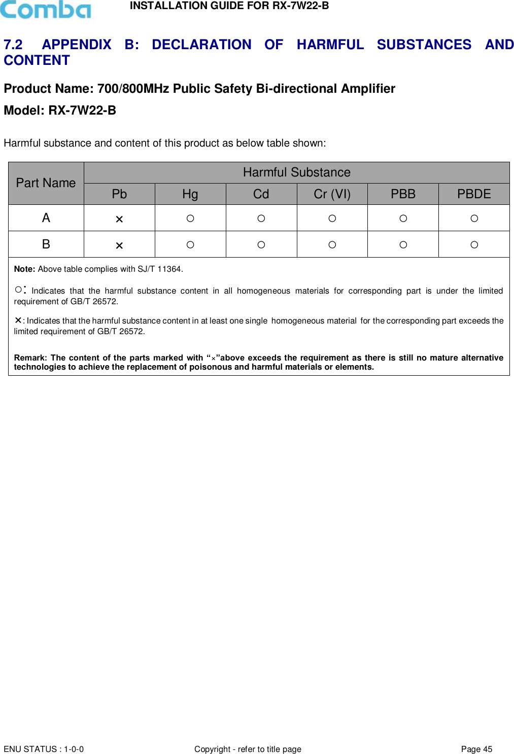
![INSTALLATION GUIDE FOR RX-7W22-B ENU STATUS : 1-0-0 Copyright - refer to title page Page 25 5 WEB GUI The PS BDA can be monitored and controlled via the WEB GUI; use the following guide to finish system parameter setting and commissioning. 5.1 WEB GUI CONNECTION Step 1: Connect the OMT port to the PC RJ45 port with the supplied RJ45 cable to set up a physical connection. Step 2: Open a browser (browser IE7.0, IE8.0, Chrome or Firefox, suggested display resolution is 1024×768), input Web GUI IP address: 192.168.8.101, click [Enter]. NOTE: DHCP and DNS are also available to login to the Web GUI. The domain name is: www.combaomt.com. Figure 8: Input IP Address Figure 9: Input Domain Name Step 3: Input User Name: admin; Password (default password: admin). Click [Log in]. Figure 10: Input User Name and Password](https://usermanual.wiki/Comba-Telecom/RX-7W22B/User-Guide-3480240-Page-24.png)
![INSTALLATION GUIDE FOR RX-7W22-B ENU STATUS : 1-0-0 Copyright - refer to title page Page 26 5.2 WEB GUI INTRODUCTION After log in, the Web GUI main screen will appear. Figure 11: Web GUI Main Screen On Comba Web GUI Home Screen, there are four Menu bars: [Devices], [Commissioning], [Firmware] and [Management]. 5.2.1 [DEVICES] The [Devices] Screen shows the equipment status, such as PA status, alarm information, etc.](https://usermanual.wiki/Comba-Telecom/RX-7W22B/User-Guide-3480240-Page-25.png)
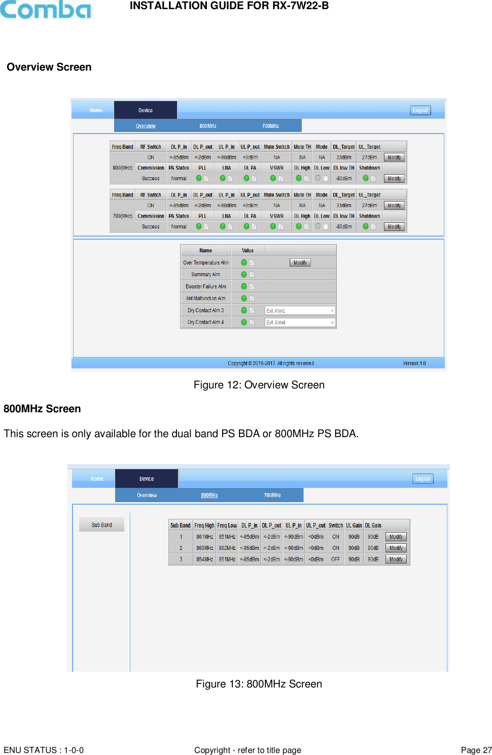
![INSTALLATION GUIDE FOR RX-7W22-B ENU STATUS : 1-0-0 Copyright - refer to title page Page 28 700MHz Screen This screen is only available for the dual band PS BDA or 700MHz PS BDA. Figure 14: 700MHz Screen 5.2.2 [COMMISSIONING] A work flow of the commissioning process is shown on [Commissioning] Screen. Click the [Start] button, the software will guide you through the commissioning step by step. For details, please refer to chapter 5.3. Figure 15: [Commissioning] Screen 5.2.3 [FIRMWARE] There are two functions on the [Firmware] bar: [upgrade] and [swap]. [Upgrade] is used to upgrade software, and [Swap] is to replace the current firmware version with the previous one. Follow the steps shown below figure to upgrade the firmware.](https://usermanual.wiki/Comba-Telecom/RX-7W22B/User-Guide-3480240-Page-27.png)
![INSTALLATION GUIDE FOR RX-7W22-B ENU STATUS : 1-0-0 Copyright - refer to title page Page 29 Figure 16: [Firmware] Screen – MCU Firmware Upgrade 5.2.4 [MANAGEMENT] Other parameters can be configured on the [Management] Screen. Figure 17: [Management] Screen](https://usermanual.wiki/Comba-Telecom/RX-7W22B/User-Guide-3480240-Page-28.png)
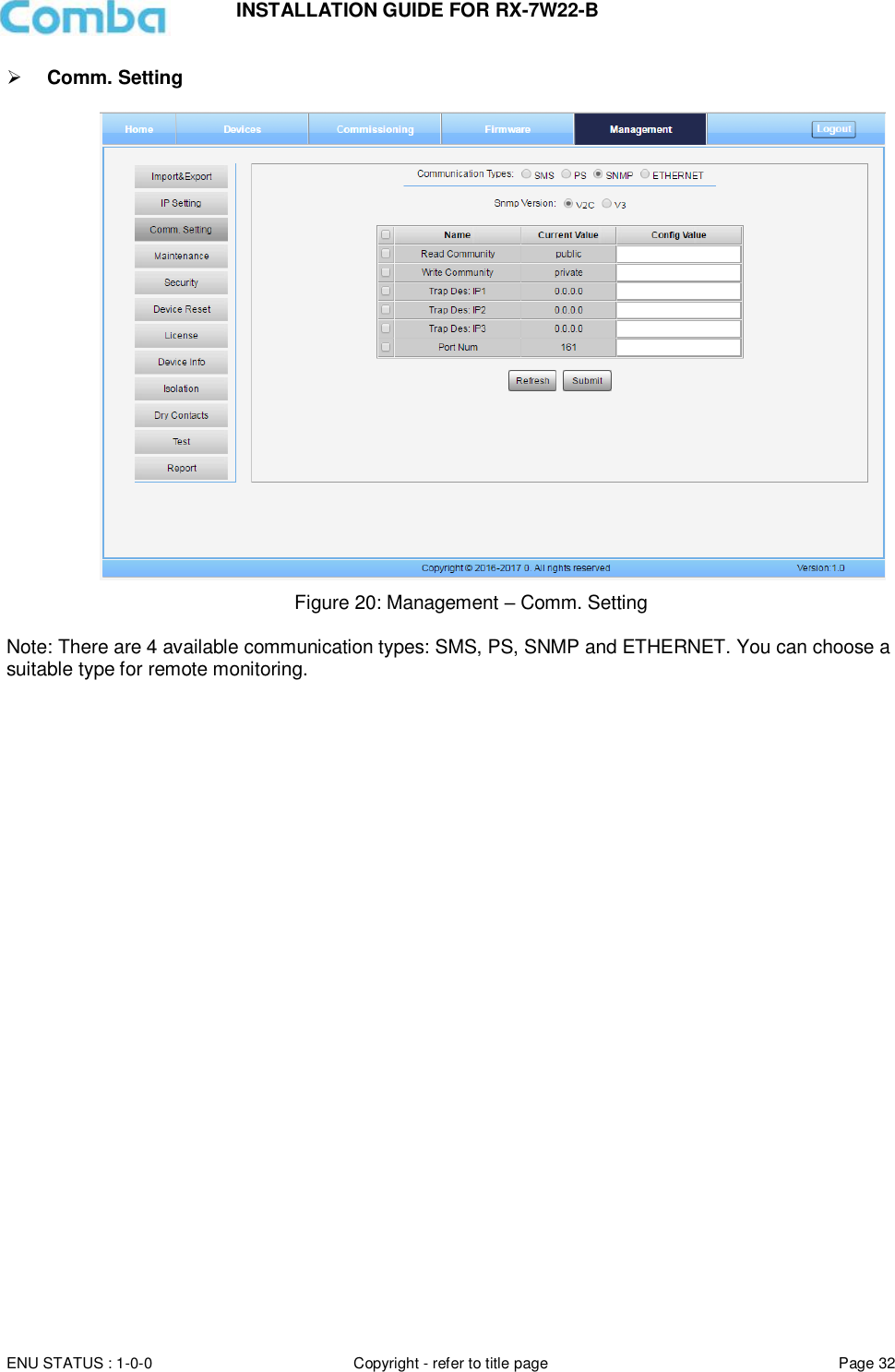
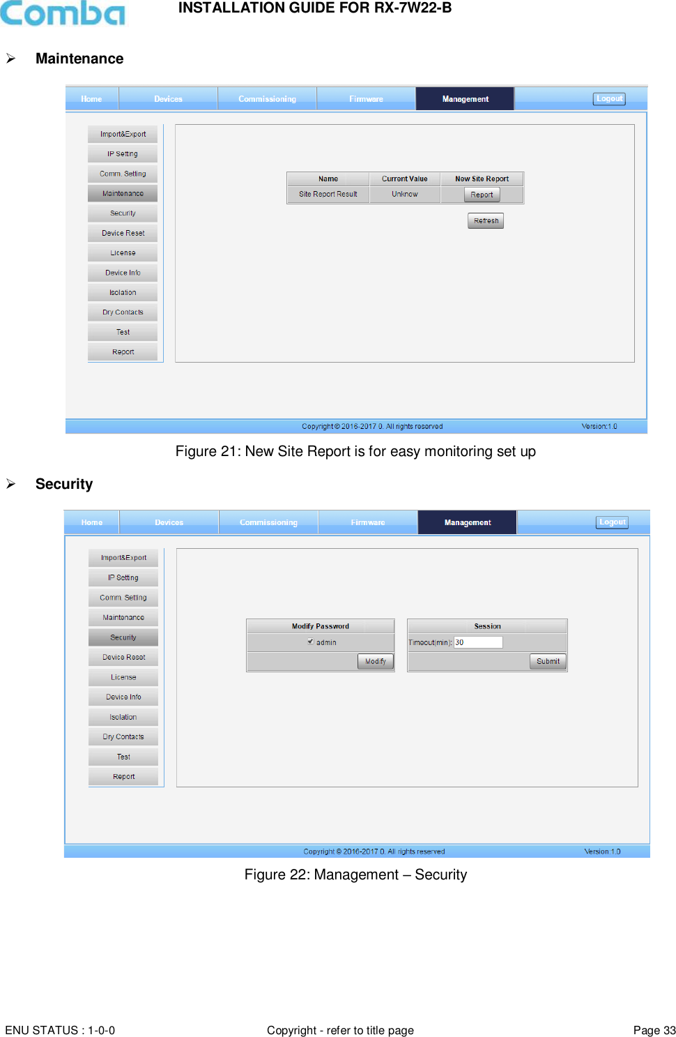
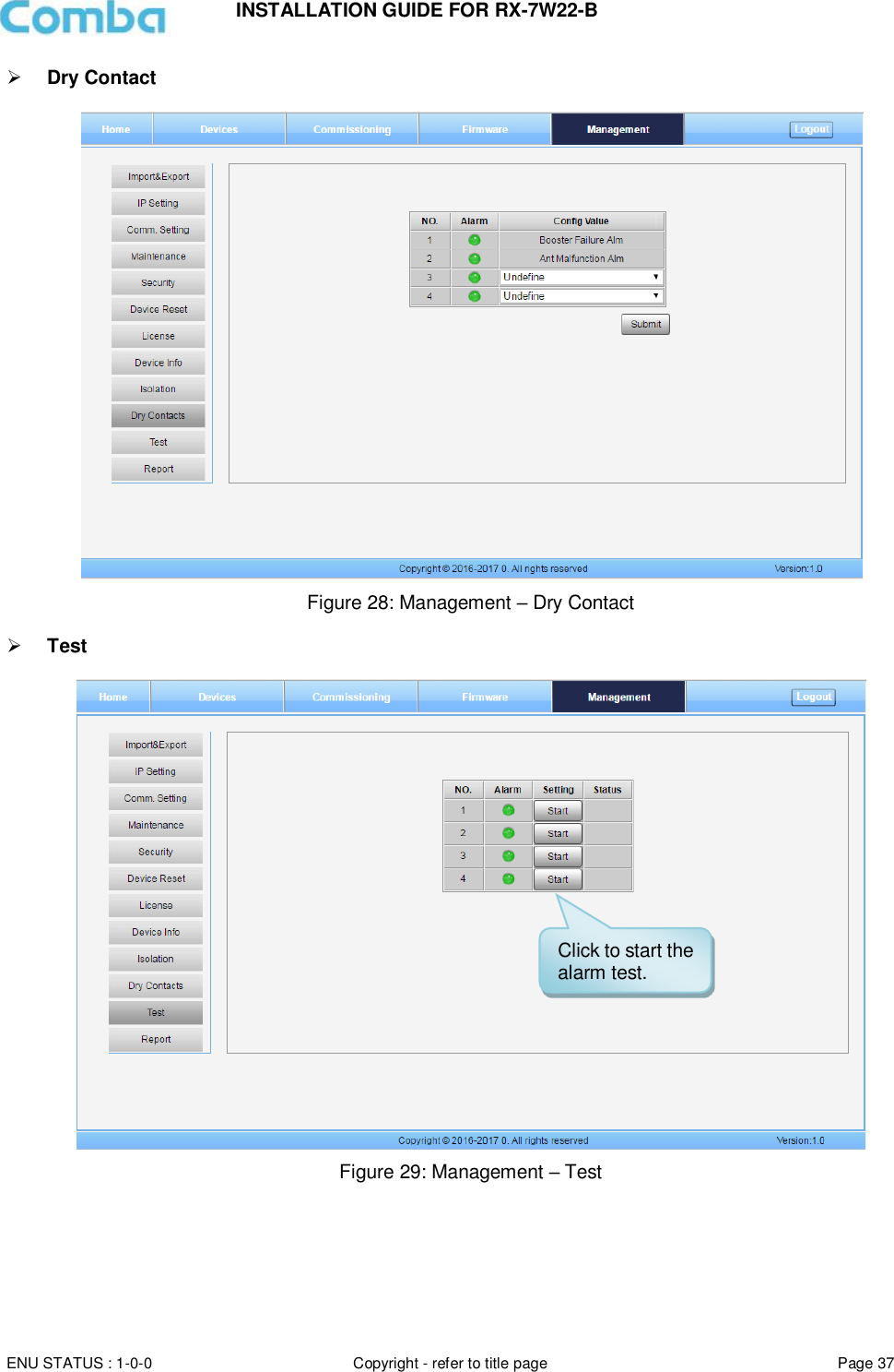
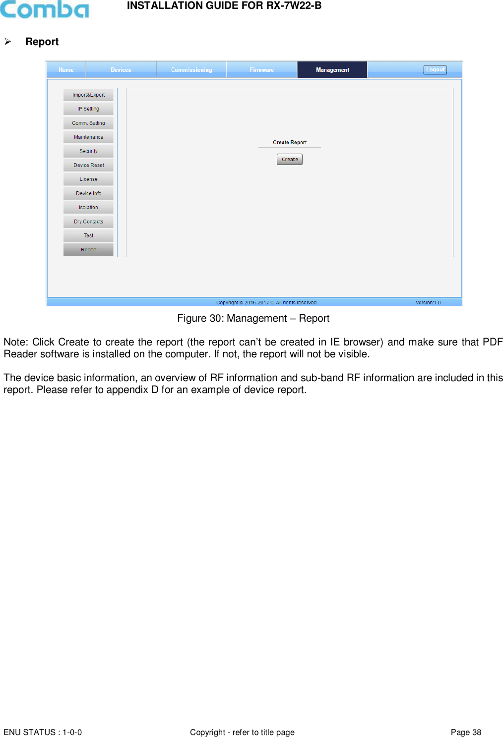
![INSTALLATION GUIDE FOR RX-7W22-B ENU STATUS : 1-0-0 Copyright - refer to title page Page 30 There are nine function bars list on the left side of the [Mangement] Screen. Inport&Export Figure 18: Management – Import & Export The parameters that can be imported / exported include sub band, alarm enable, ATT value, RF switch, and DL output power. This function can help users quickly configure PS BDA parameters. For example, if one PS BDA is finished configuration, users can export the parameters and save it as a file on the PC, and then import this file to other PS BDAs for faster set up of additional PS BDAs.](https://usermanual.wiki/Comba-Telecom/RX-7W22B/User-Guide-3480240-Page-29.png)
![INSTALLATION GUIDE FOR RX-7W22-B ENU STATUS : 1-0-0 Copyright - refer to title page Page 34 Click , [Modify Password] window will pop-up. Figure 23: Modify Password Note: Username cannot be modified. Device Reset Figure 24: Management – Device Reset Note: Click , all the parameters and alarms will be reset to factory default value. The Device Reset process will last about 2~4 minutes. For PMU monitor reset, users need to re-login to the WEB GUI.](https://usermanual.wiki/Comba-Telecom/RX-7W22B/User-Guide-3480240-Page-33.png)
![INSTALLATION GUIDE FOR RX-7W22-B ENU STATUS : 1-0-0 Copyright - refer to title page Page 36 Device Info Figure 26: Management – Device Info Note: Users can input a maximum of 30 characters in Device Info. Isolation Figure 27: Management – Isolation Note: This Step is the same as step 3 of [Commissioning]. Users can check isolation again by clicking the Check button.](https://usermanual.wiki/Comba-Telecom/RX-7W22B/User-Guide-3480240-Page-35.png)
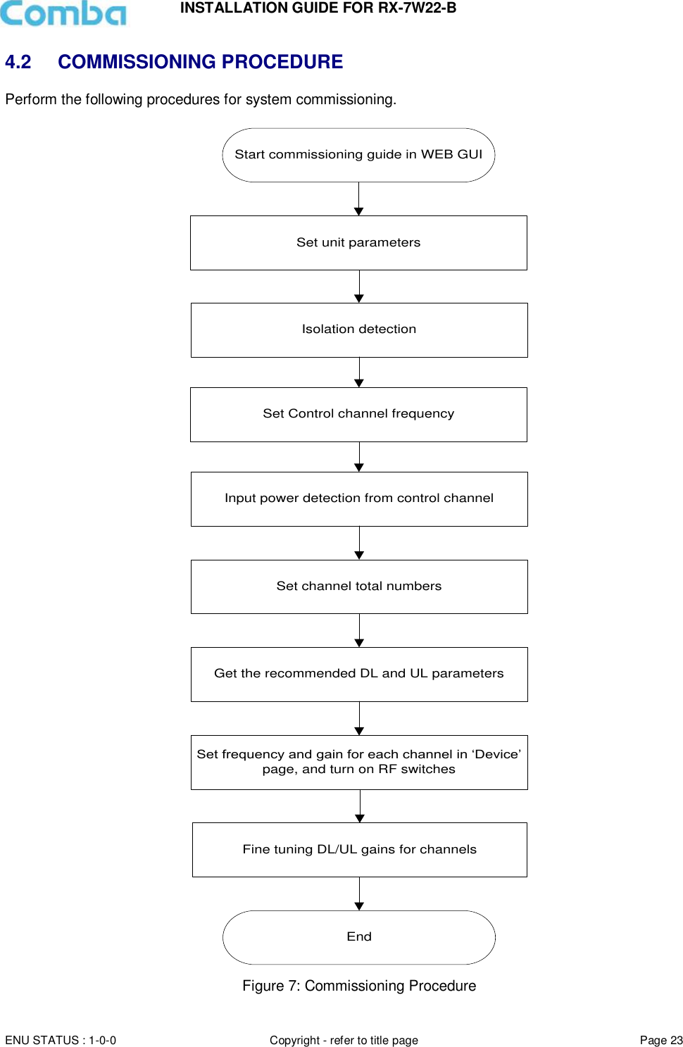
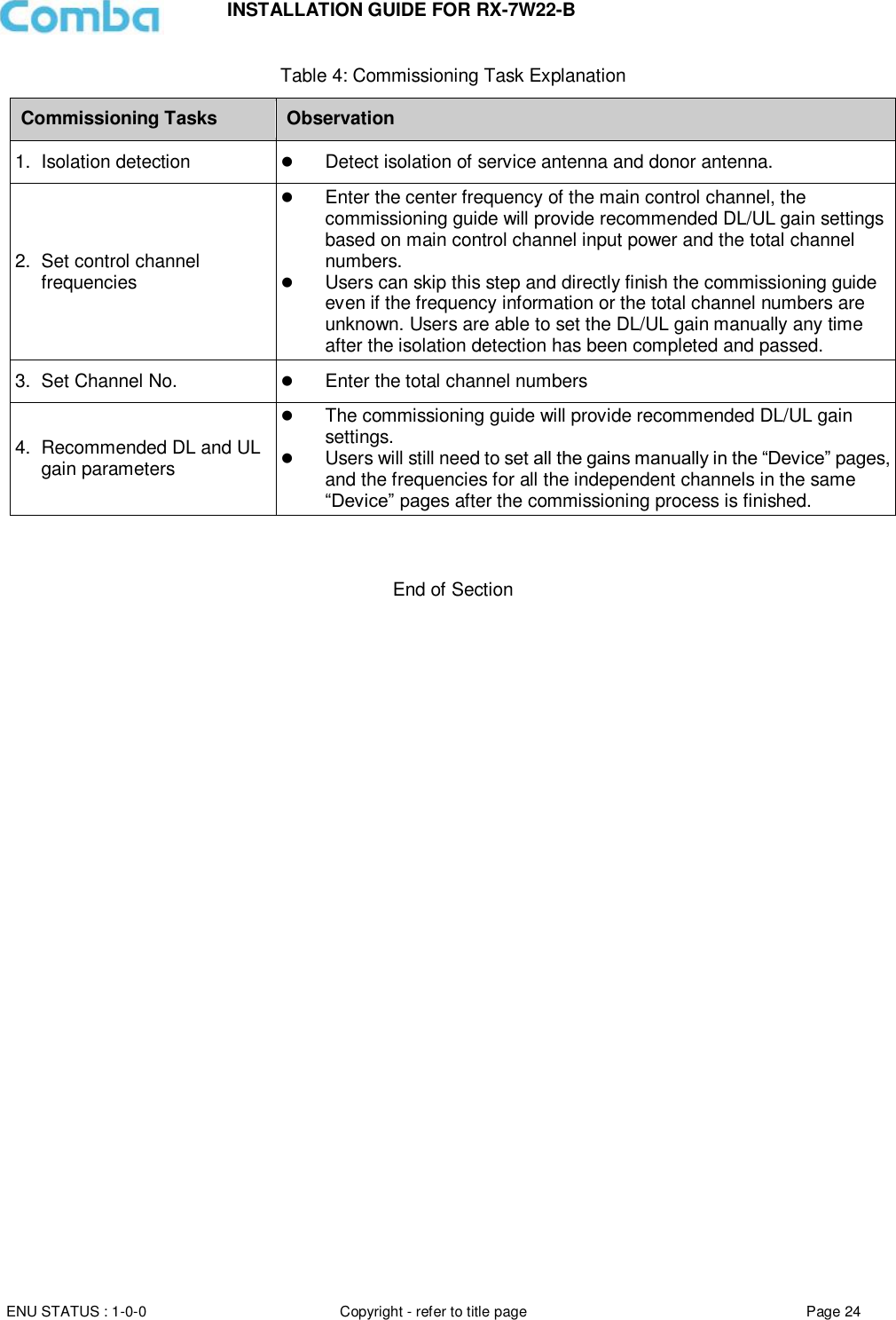
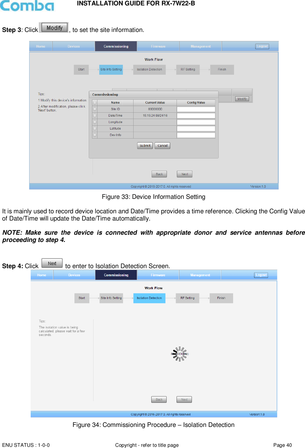
![INSTALLATION GUIDE FOR RX-7W22-B ENU STATUS : 1-0-0 Copyright - refer to title page Page 39 5.3 COMMISSIONING PROCEDURE To complete the installation and commissioning, users need to follow the steps below. Step 1: Click the Menu bar [Commissioning] on home screen, a work flow will be displayed. Figure 31: Commissioning Procedure – Start Step 2: Click to start the process. Figure 32: Commissioning Procedure – Site Info. Setting](https://usermanual.wiki/Comba-Telecom/RX-7W22B/User-Guide-3480240-Page-38.png)
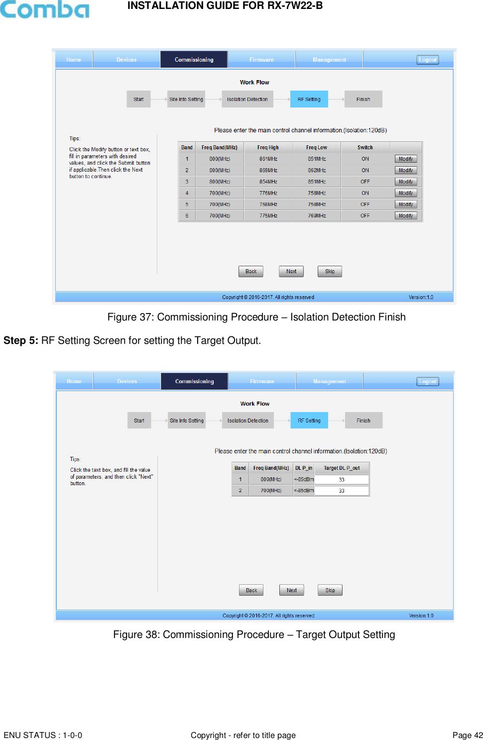
![INSTALLATION GUIDE FOR RX-7W22-B ENU STATUS : 1-0-0 Copyright - refer to title page Page 41 Select a frequency band (RFU) that needs to be commissioned. Click to start Isolation Detecting, then a [Confirm] window will pop-up. Click to continue. If isolation detection passes, the process will go to the RF Settiing Screen shown as Figure 38. If failed, a Tips window will pop-up, users need to check whether the system isolation is adequate. NOTE: At the end of the first frequency band commissioning, users can start other frequency band commissioning. Figure 35: Commissioning Procedure – Isolation Detection Confirm Figure 36: Commissioning Procedure – Isolation Detection Failed](https://usermanual.wiki/Comba-Telecom/RX-7W22B/User-Guide-3480240-Page-40.png)
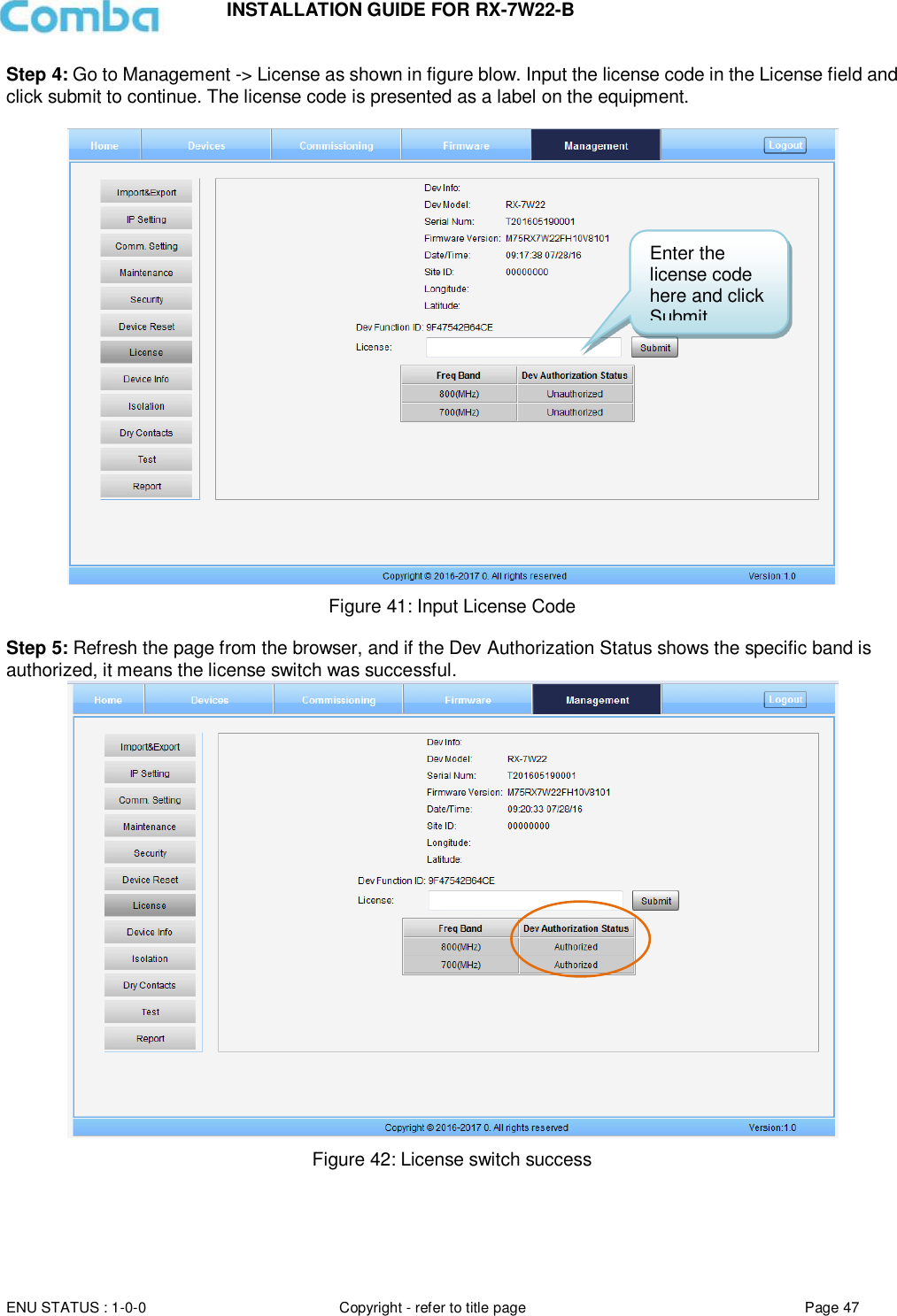
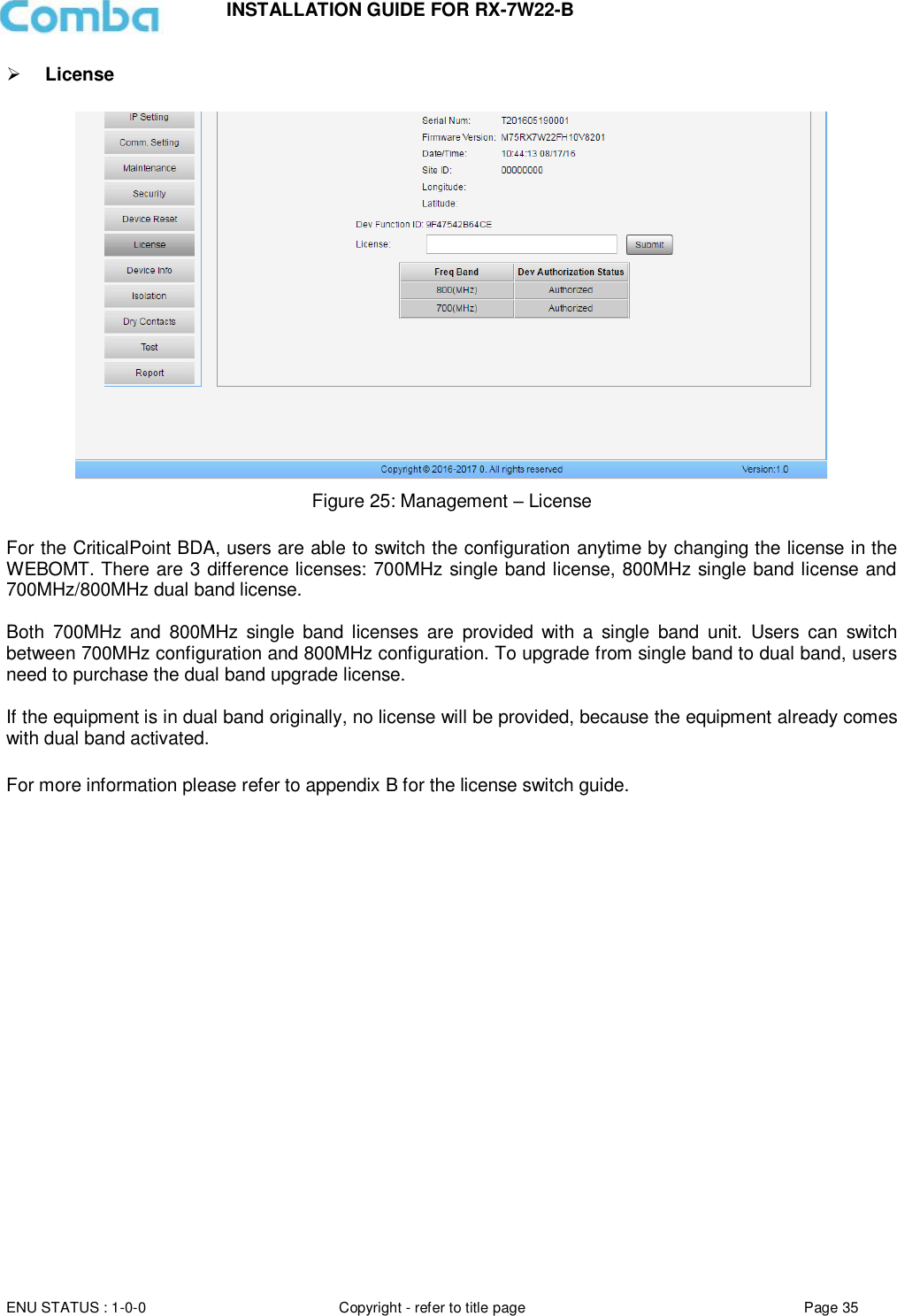
![INSTALLATION GUIDE FOR RX-7W22-B ENU STATUS : 1-0-0 Copyright - refer to title page Page 46 7.3 APPENDIX C: LICENSE SWITCH QUICK GUIDE For CriticalPoint BDA, users are able to switch the configuration anytime by changing the license in the WEBOMT. There are 3 difference licenses: 700MHz single band license, 800MHz single band license and 700MHz/800MHz dual band license. Both 700MHz and 800MHz single band licenses are provided with a single band unit. Users can switch between 700MHz configuration and 800MHz configuration. To upgrade from single band to dual band configurations, users need to purchase the dual band upgrade license.. If the equipment is in dual band originally, no license will be provided, because the equipment already comes with dual band activated. Please follow the steps to switch configuration by license: Step 1: Connect the unit “OMT port” to a laptop with an Ethernet cable. Step 2: Wait approximately 1 minute until the IP address is established. Open the browser (Chrome or Firefox is recommended), login to WEBGUI with: www.combaomt.com or 192.168.8.101. Step 3: Input User Name: admin; Password: (default: admin). Click [Log in]. Figure 40: Input User Name and Password](https://usermanual.wiki/Comba-Telecom/RX-7W22B/User-Guide-3480240-Page-45.png)