Comba Telecom RX4122-B UHF Public Safety Bi-directional Amplifier User Manual
Comba Telecom Ltd. UHF Public Safety Bi-directional Amplifier
UserManual.wiki
>
Comba Telecom
>
RX4122 B User Manual
User manual
Navigation menu
Upload a User Manual
Namespaces
Wiki Guide
HTML
PDF
Info
Views
User Manual
Discussion / Help
Navigation
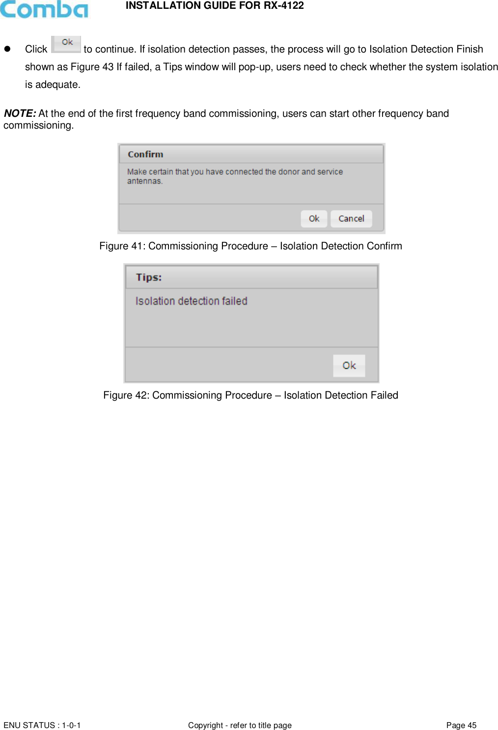
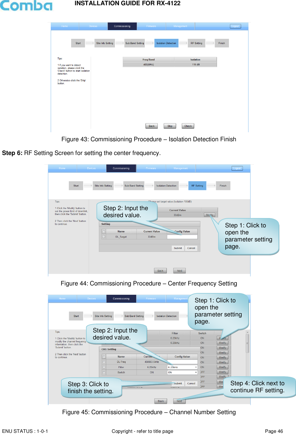
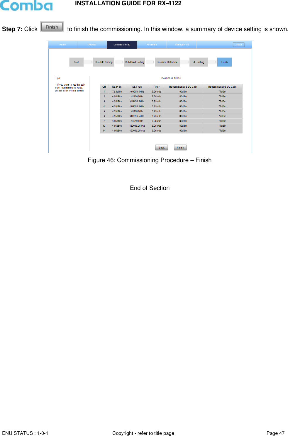
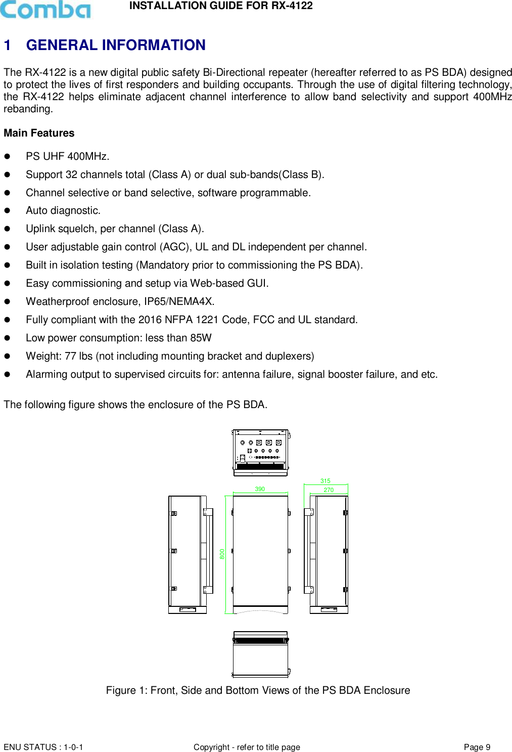
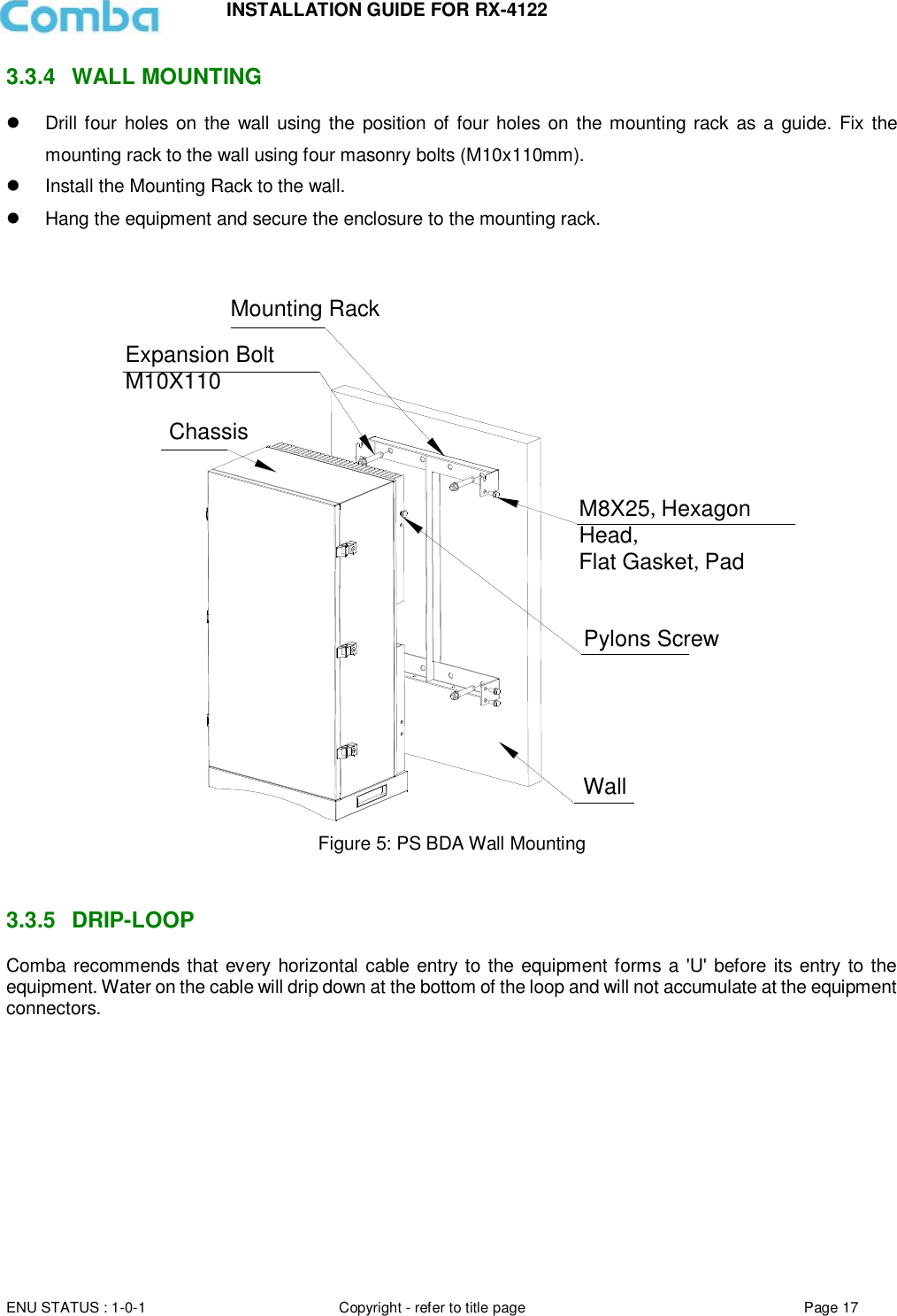
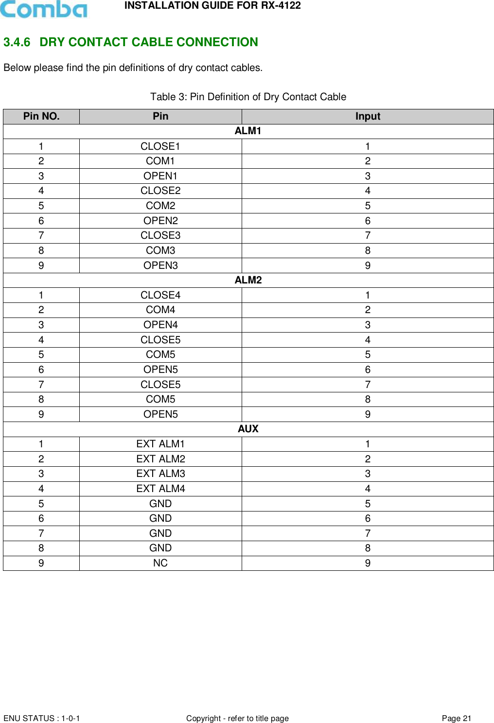
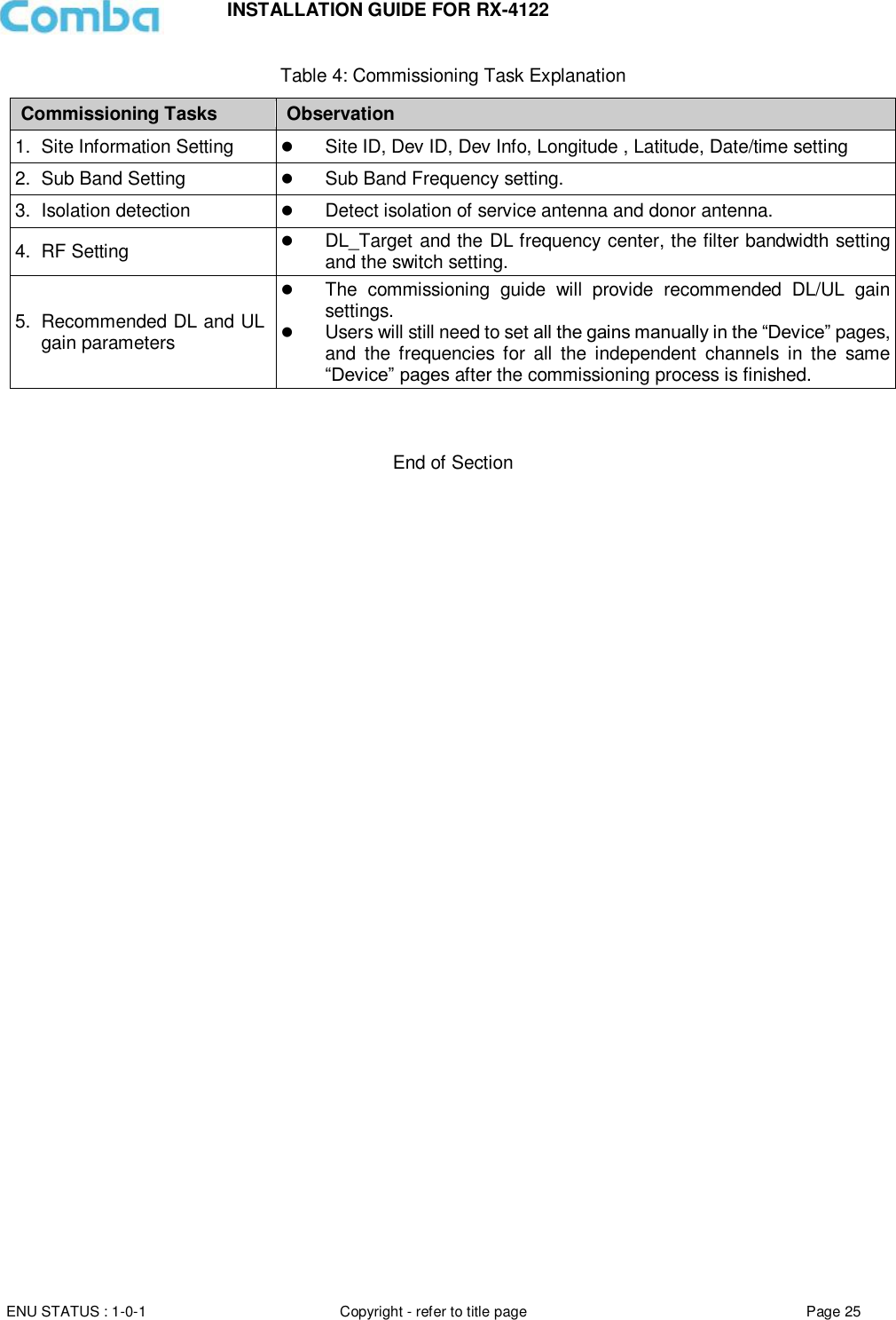
![INSTALLATION GUIDE FOR RX-4122 ENU STATUS : 1-0-1 Copyright - refer to title page Page 3 0.1 CONTENTS Section Page 0.1 CONTENTS ................................................................................................................................. 3 0.2 INDEX TO FIGURES AND TABLES ......................................................................................... 5 0.3 HISTORY ..................................................................................................................................... 6 0.4 GLOSSARY OF TERMS ............................................................................................................ 7 0.5 SAFETY NOTICES AND ADMONISHMENTS ......................................................................... 8 1 GENERAL INFORMATION ........................................................................................................ 9 2 EQUIPMENT DESCRIPTION .................................................................................................. 10 2.1 FUNCTIONAL BLOCK DIAGRAM ........................................................................................... 10 2.2 EQUIPMENT LAYOUT ............................................................................................................. 11 2.3 EQUIPMENT CONSTITUTION ................................................................................................ 12 3 INSTALLATION ......................................................................................................................... 13 3.1 WARNINGS AND ALERTS ...................................................................................................... 13 3.2 SITE PLANNING CONSIDERATIONS .................................................................................... 14 3.2.1 SITE PLANNING ....................................................................................................................... 14 3.2.2 INSTALLATION CHECKLIST................................................................................................... 15 3.3 INSTALLATION PROCEDURES ............................................................................................. 16 3.3.1 GOODS INWARDS INSPECTION........................................................................................... 16 3.3.2 TOOLS ....................................................................................................................................... 16 3.3.3 PREPARATION ......................................................................................................................... 16 3.3.4 WALL MOUNTING .................................................................................................................... 17 3.3.5 DRIP-LOOP ............................................................................................................................... 17 3.4 EQUIPMENT CONNECTORS ................................................................................................. 18 3.4.1 PS BDA CONNECTORS .......................................................................................................... 18 3.4.2 PS BDA LED Indicators ............................................................................................................ 20 3.4.3 GROUNDING CONNECTION .................................................................................................. 20 3.4.4 RF CABLE CONNECTION ....................................................................................................... 20 3.4.5 ETHERNET CONNECTION ..................................................................................................... 20 3.4.6 DRY CONTACT CABLE CONNECTION ................................................................................ 21 4 COMMISSIONING .................................................................................................................... 23 4.1 PRE-COMMISSIONING TASKS .............................................................................................. 23 4.2 COMMISSIONING PROCEDURE ........................................................................................... 24 5 WEB GUI ................................................................................................................................... 26 5.1 WEB GUI CONNECTION ......................................................................................................... 26 5.2 WEB GUI INTRODUCTION ..................................................................................................... 27 5.2.1 [DEVICES] ................................................................................................................................. 27 5.2.2 [COMMISSIONING] .................................................................................................................. 29 5.2.3 [FIRMWARE] ............................................................................................................................. 29 5.2.4 [MANAGEMENT]....................................................................................................................... 31 5.3 COMMISSIONING PROCEDURE ........................................................................................... 41 6 MAINTENANCE ........................................................................................................................ 48 7 APPENDICES ........................................................................................................................... 49 7.1 APPENDIX A: ............................................................................................................................ 49 7.2 APPENDIX B: TOOLS .............................................................................................................. 51](https://usermanual.wiki/Comba-Telecom/RX4122-B/User-Guide-3847467-Page-3.png)
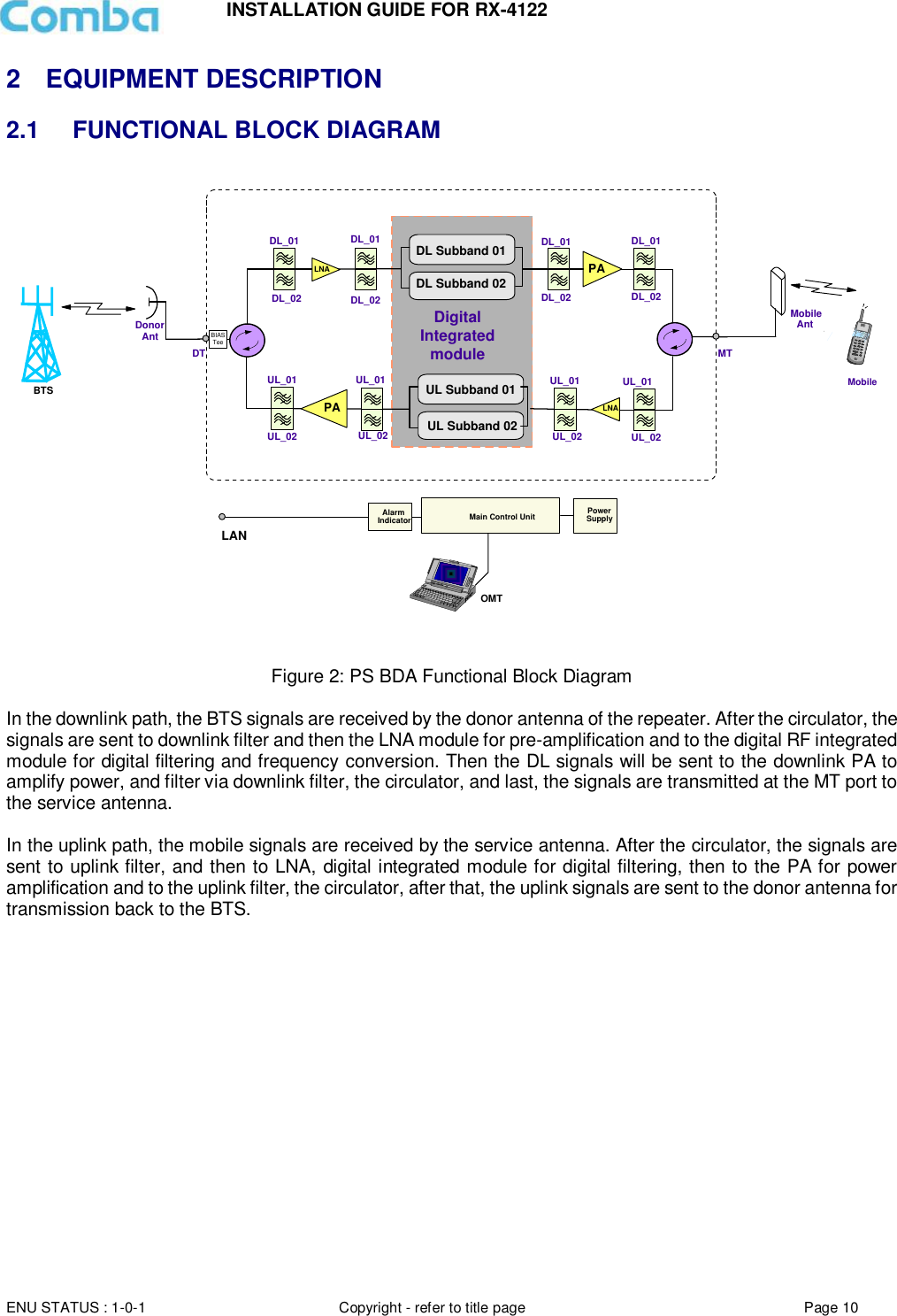
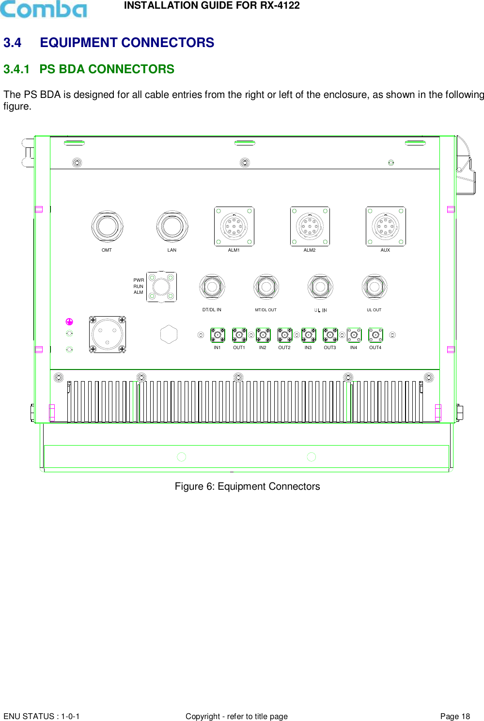
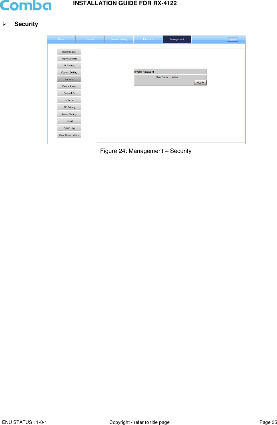
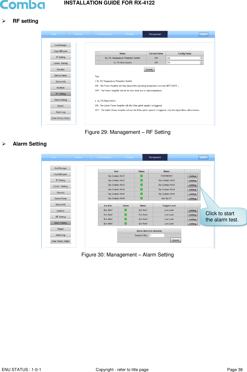
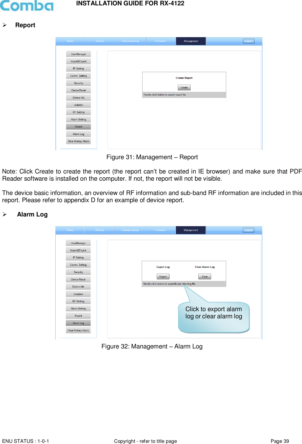
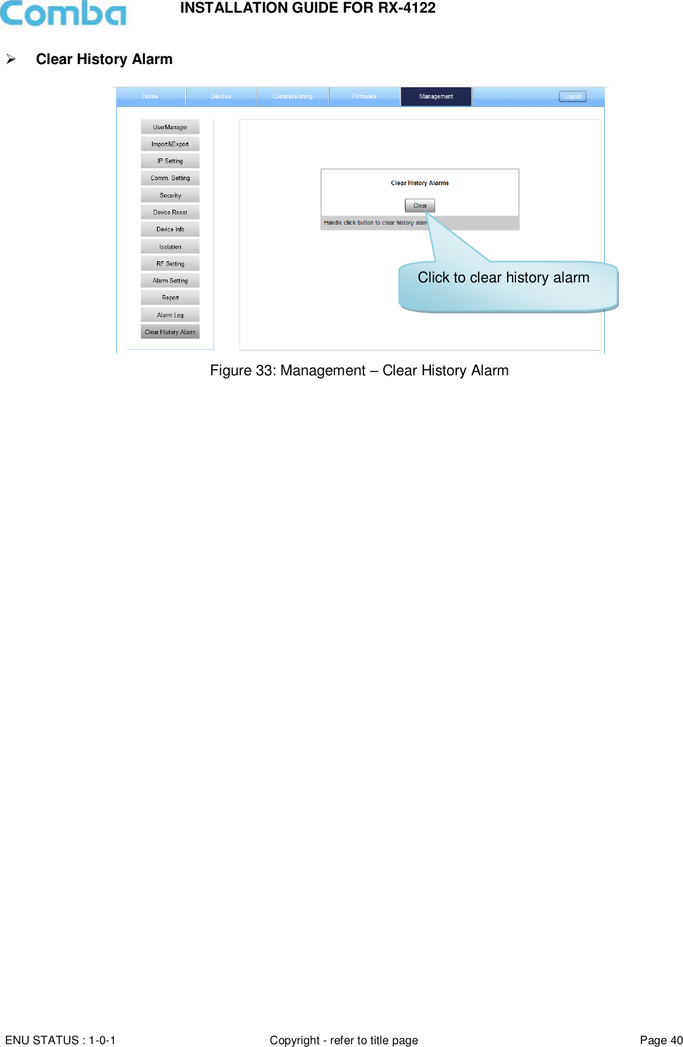
![INSTALLATION GUIDE FOR RX-4122 ENU STATUS : 1-0-1 Copyright - refer to title page Page 5 0.2 INDEX TO FIGURES AND TABLES Figure 1: Front, Side and Bottom Views of the PS BDA Enclosure ................................................................ 9 Figure 2: PS BDA Functional Block Diagram ............................................................................................... 10 Figure 3: Layout of the PS BDA .................................................................................................................. 11 Figure 4: Mounting Rack Overview ............................................................................................................. 16 Figure 5: PS BDA Wall Mounting ................................................................................................................ 17 Figure 6: Equipment Connectors................................................................................................................. 18 Figure 7: Commissioning Procedure ........................................................................................................... 24 Figure 8: Input IP Address .......................................................................................................................... 26 Figure 9: Input Domain Name ..................................................................................................................... 26 Figure 10: Input User Name and Password ................................................................................................. 26 Figure 11: Web GUI Main Screen ............................................................................................................... 27 Figure 12: Overview Screen........................................................................................................................ 27 Figure 13: 400MHz Screen 1 ...................................................................................................................... 28 Figure 14: 400MHz Screen 2 ...................................................................................................................... 28 Figure 15: 400MHz Screen ......................................................................................................................... 29 Figure 16: [Commissioning] Screen ............................................................................................................ 29 Figure 17: [Firmware] Screen – MCU Firmware Upgrade ............................................................................ 30 Figure 18: [Firmware] Screen – Firmware Swap .......................................................................................... 30 Figure 19: [Firmware] Screen – Module Update .......................................................................................... 30 Figure 20: [Management] Screen ................................................................................................................ 31 Figure 21: Management – Import & Export .................................................................................................. 32 Figure 22: Management – IP Setting ........................................................................................................... 33 Figure 23: Management – Comm. Setting ................................................................................................... 34 Figure 24: Management – Security ............................................................................................................. 35 Figure 25: Modify Password........................................................................................................................ 36 Figure 26: Management – Device Reset ..................................................................................................... 36 Figure 27: Management – Device Info ........................................................................................................ 37 Figure 28: Management – Isolation ............................................................................................................. 37 Figure 29: Management – RF Setting ......................................................................................................... 38 Figure 30: Management – Alarm Setting ..................................................................................................... 38 Figure 31: Management – Report ............................................................................................................... 39 Figure 32: Management – Alarm Log .......................................................................................................... 39 Figure 33: Management – Clear History Alarm ............................................................................................ 40 Figure 34: Commissioning Procedure – Start .............................................................................................. 41 Figure 35: Commissioning Procedure – Site Info. Setting ............................................................................ 41 Figure 36: Device Information Setting ......................................................................................................... 42 Figure 37: Device Sub Band Setting-Class A .............................................................................................. 42 Figure 38: Channel parameters setting-Class A .......................................................................................... 43 Figure 39: Device sub-band setting-Class B................................................................................................ 44 Figure 40: Commissioning Procedure – Isolation Detection ......................................................................... 44 Figure 41: Commissioning Procedure – Isolation Detection Confirm ............................................................ 45 Figure 42: Commissioning Procedure – Isolation Detection Failed .............................................................. 45 Figure 43: Commissioning Procedure – Isolation Detection Finish ............................................................... 46 Figure 44: Commissioning Procedure – Center Frequency Setting .............................................................. 46 Figure 45: Commissioning Procedure – Channel Number Setting ............................................................... 46 Figure 46: Commissioning Procedure – Finish ............................................................................................ 47 Table 1: Equipment Connectors .................................................................................................................. 19 Table 2: LED Indicators .............................................................................................................................. 20 Table 3: Pin Definition of Dry Contact Cable ............................................................................................... 21 Table 4: Commissioning Task Explanation .................................................................................................. 25](https://usermanual.wiki/Comba-Telecom/RX4122-B/User-Guide-3847467-Page-5.png)
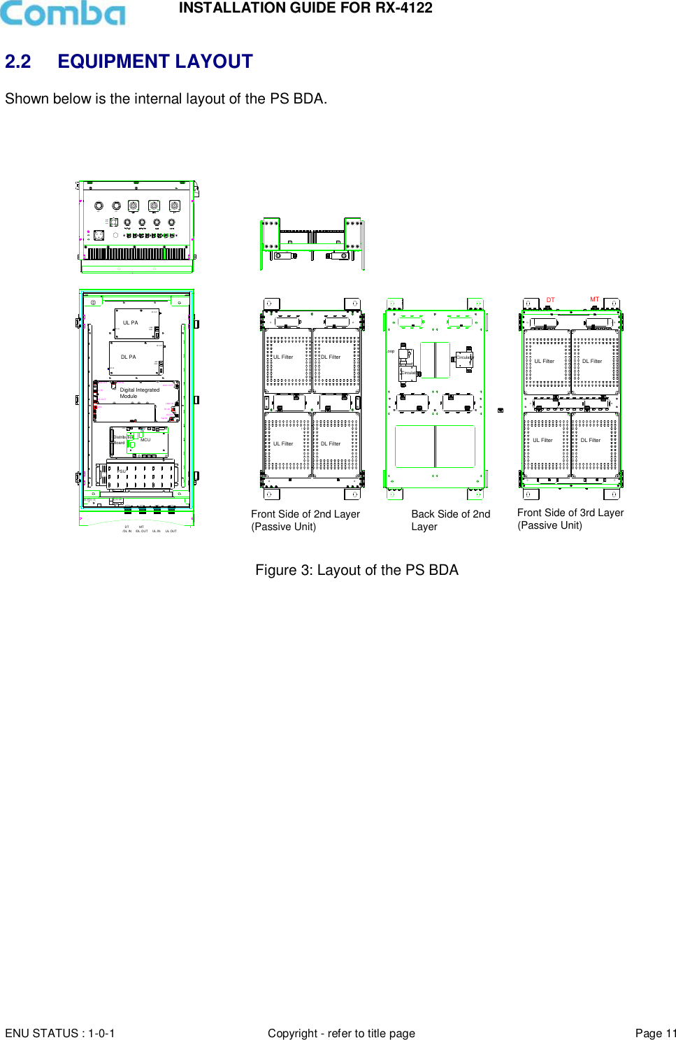
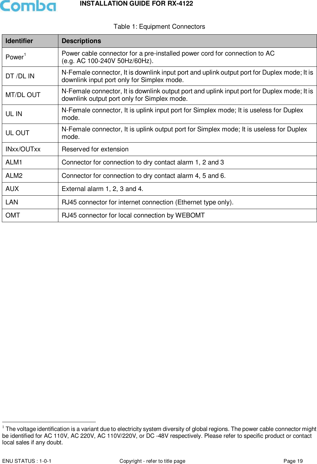
![INSTALLATION GUIDE FOR RX-4122 ENU STATUS : 1-0-1 Copyright - refer to title page Page 26 5 WEB GUI The PS BDA can be monitored and controlled via the WEB GUI; use the following guide to finish system parameter setting and commissioning. 5.1 WEB GUI CONNECTION Step 1: Connect the OMT port to the PC RJ45 port with the supplied RJ45 cable to set up a physical connection. Step 2: Open a browser (browser IE7.0, IE8.0, Chrome or Firefox, suggested display resolution is 1024×768), input Web GUI IP address: 192.168.8.101, click [Enter]. NOTE: DHCP and DNS are also available to login to the Web GUI. The domain name is: www.combaomt.com. Advise to clear all the history record of Browse before connecting BDA every time. Figure 8: Input IP Address Figure 9: Input Domain Name Step 3: Input User Name: admin; Password (default password: admin). Click [Log in]. Figure 10: Input User Name and Password](https://usermanual.wiki/Comba-Telecom/RX4122-B/User-Guide-3847467-Page-26.png)
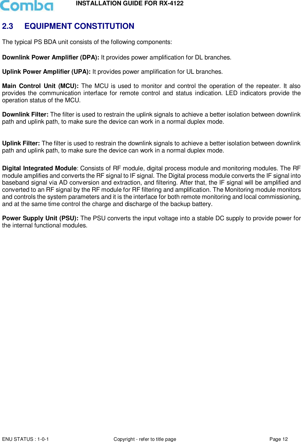
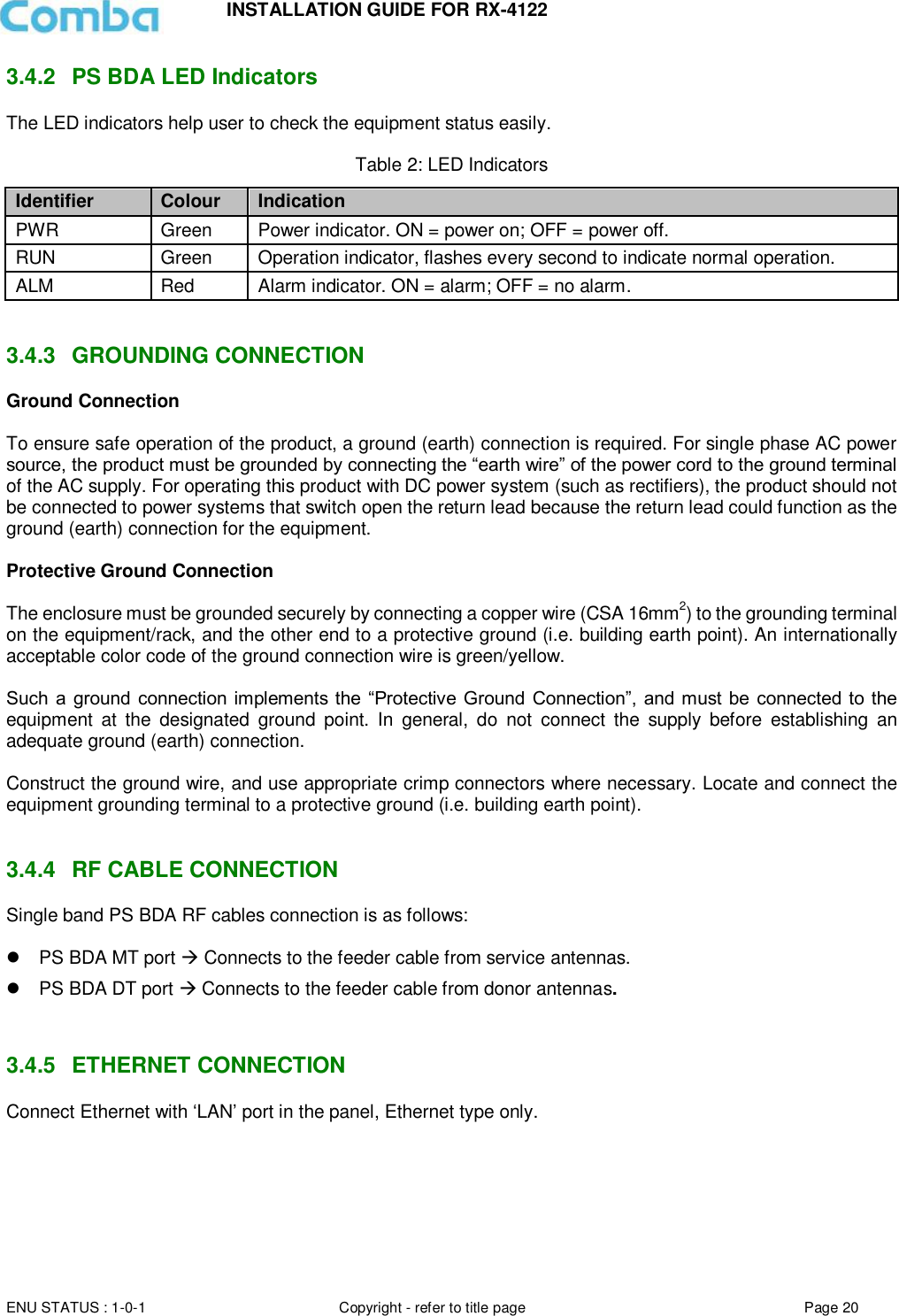
![INSTALLATION GUIDE FOR RX-4122 ENU STATUS : 1-0-1 Copyright - refer to title page Page 27 5.2 WEB GUI INTRODUCTION After log in, the Web GUI main screen will appear. Figure 11: Web GUI Main Screen On Comba Web GUI Home Screen, there are four Menu bars: [Devices], [Commissioning], [Firmware] and [Management]. 5.2.1 [DEVICES] The [Devices] Screen shows the equipment status, such as PA status, alarm information, etc. Overview Screen Figure 12: Overview Screen Shows the basic information about the PS BDA Indicates the equipment status Indicating alarm status Click to enable /disable alarm Indicating alarm status Click to enable /disable alarm](https://usermanual.wiki/Comba-Telecom/RX4122-B/User-Guide-3847467-Page-27.png)
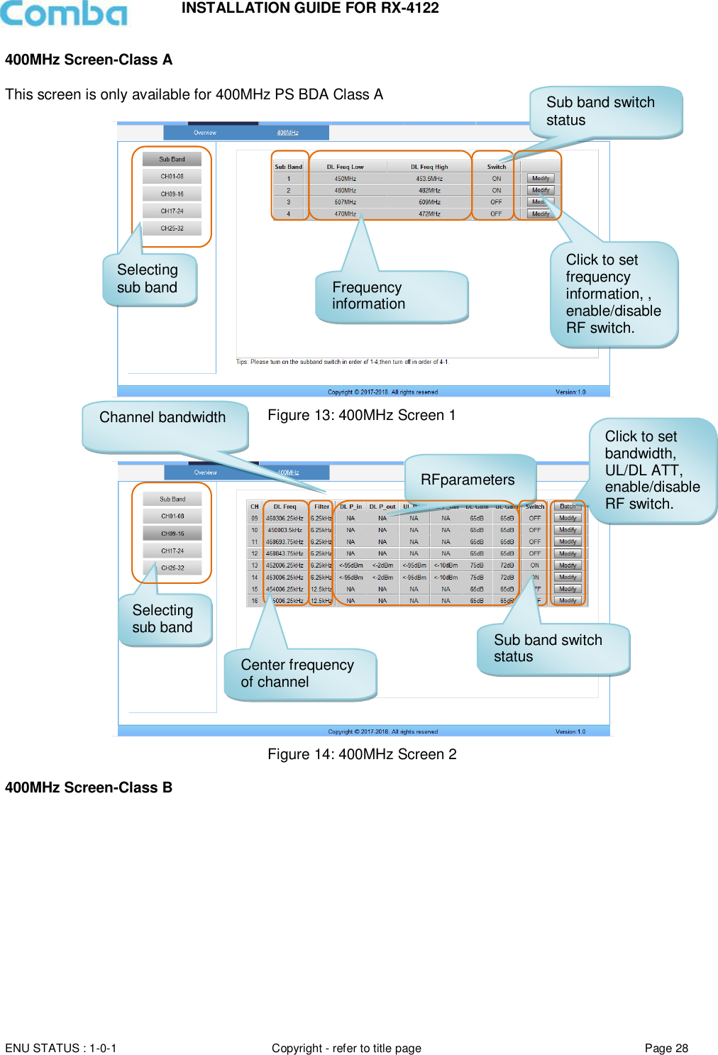
![INSTALLATION GUIDE FOR RX-4122 ENU STATUS : 1-0-1 Copyright - refer to title page Page 29 Figure 15: 400MHz Screen 5.2.2 [COMMISSIONING] A work flow of the commissioning process is shown on [Commissioning] Screen. Click the [Start] button, the software will guide you through the commissioning step by step. For details, please refer to chapter 5.3. Figure 16: [Commissioning] Screen 5.2.3 [FIRMWARE] There are two functions on the [Firmware] bar: [upgrade] and [swap]. [Upgrade] is used to upgrade software, and [Swap] is to replace the current firmware version with the previous one. Follow the steps shown below figure to upgrade the firmware. Click to set Freq Low and High, DL/UL Gain, Enable/disable RF switch. DL Freq Low and High of sub-bands RF parameters of sub-bands Sub-bands switch status](https://usermanual.wiki/Comba-Telecom/RX4122-B/User-Guide-3847467-Page-29.png)
![INSTALLATION GUIDE FOR RX-4122 ENU STATUS : 1-0-1 Copyright - refer to title page Page 30 Figure 17: [Firmware] Screen – MCU Firmware Upgrade Figure 18: [Firmware] Screen – Firmware Swap Figure 19: [Firmware] Screen – Module Update Step 1: Click to select the file for upgrading. Step 2: Click to finish the software upgrading. Click to swap the firmware to the previous version Step 2: Click to select the file. Step 3: Click to finish the upgrading. Step 1: Check the module that needs to be updated.](https://usermanual.wiki/Comba-Telecom/RX4122-B/User-Guide-3847467-Page-30.png)
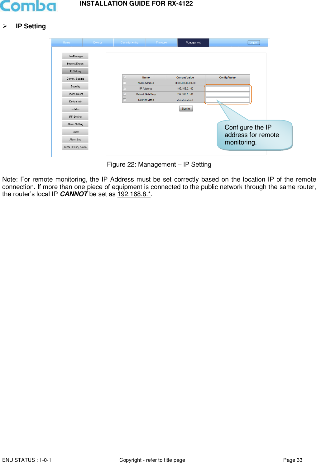
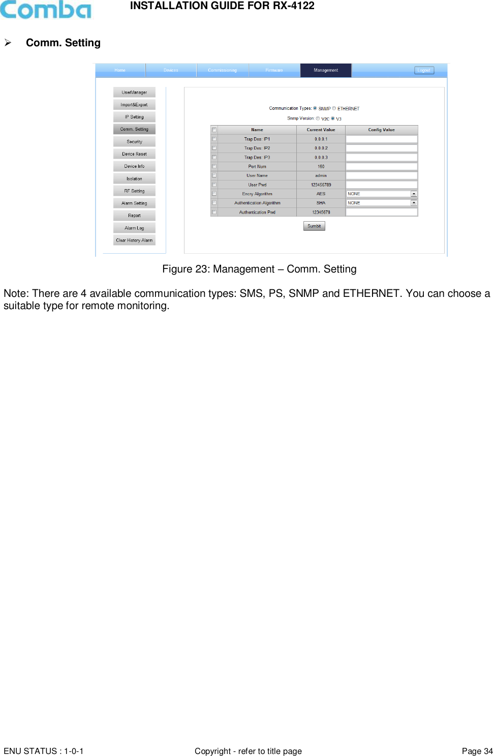
![INSTALLATION GUIDE FOR RX-4122 ENU STATUS : 1-0-1 Copyright - refer to title page Page 31 5.2.4 [MANAGEMENT] Other parameters can be configured on the [Management] Screen. Figure 20: [Management] Screen Management menu, click Enter to each page for parameters setting.](https://usermanual.wiki/Comba-Telecom/RX4122-B/User-Guide-3847467-Page-31.png)
![INSTALLATION GUIDE FOR RX-4122 ENU STATUS : 1-0-1 Copyright - refer to title page Page 32 There are nine function bars list on the left side of the [Mangement] Screen. Inport&Export Figure 21: Management – Import & Export The parameters that can be imported / exported include sub band, alarm enable, ATT value, RF switch, and DL output power. This function can help users quickly configure PS BDA parameters. For example, if one PS BDA is finished configuration, users can export the parameters and save it as a file on the PC, and then import this file to other PS BDAs for faster set up of additional PS BDAs. Click to import/export the configuration parameters.](https://usermanual.wiki/Comba-Telecom/RX4122-B/User-Guide-3847467-Page-32.png)
![INSTALLATION GUIDE FOR RX-4122 ENU STATUS : 1-0-1 Copyright - refer to title page Page 36 Click , [Modify Password] window will pop-up. Figure 25: Modify Password Note: Username cannot be modified. Device Reset Figure 26: Management – Device Reset Note: Click , all the parameters and alarms will be reset to factory default value. The Device Reset process will last about 2~4 minutes. For PMU monitor reset, users need to re-login to the WEB GUI.](https://usermanual.wiki/Comba-Telecom/RX4122-B/User-Guide-3847467-Page-36.png)
![INSTALLATION GUIDE FOR RX-4122 ENU STATUS : 1-0-1 Copyright - refer to title page Page 37 Device Info Figure 27: Management – Device Info Note: Users can input a maximum of 30 characters in Device Info. Isolation Figure 28: Management – Isolation Note: This Step is the same as step 5 of [Commissioning]. Users can check isolation again by clicking the Check button, the detection range is from 65dB to 125dB. Click here to get PC time. Input device information.](https://usermanual.wiki/Comba-Telecom/RX4122-B/User-Guide-3847467-Page-37.png)
![INSTALLATION GUIDE FOR RX-4122 ENU STATUS : 1-0-1 Copyright - refer to title page Page 41 5.3 COMMISSIONING PROCEDURE To complete the installation and commissioning, users need to follow the steps below. Step 1: Click the Menu bar [Commissioning] on home screen, a work flow will be displayed. Figure 34: Commissioning Procedure – Start Step 2: Click to start the process. Figure 35: Commissioning Procedure – Site Info. Setting Step 3: Click , to set the site information.](https://usermanual.wiki/Comba-Telecom/RX4122-B/User-Guide-3847467-Page-41.png)
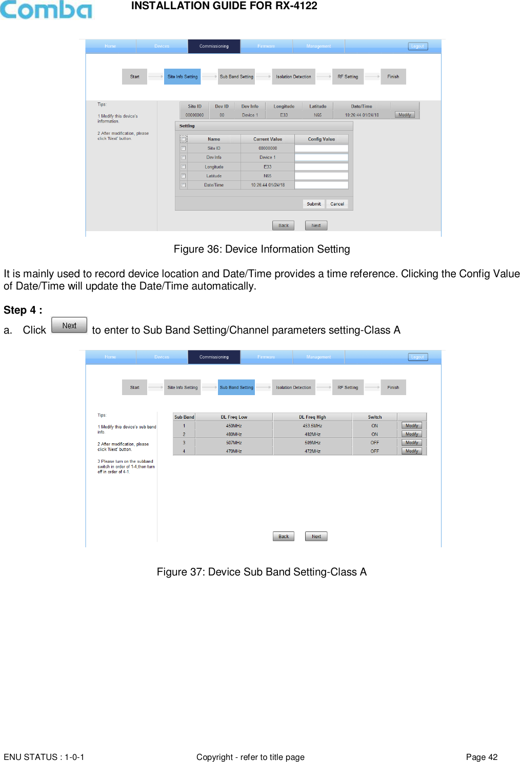
![INSTALLATION GUIDE FOR RX-4122 ENU STATUS : 1-0-1 Copyright - refer to title page Page 43 Figure 38: Channel parameters setting-Class A Reminder: Make sure the frequency of sub-bands match the actual frequency of filters, or BDA cannot work normally. If the frequency is within [450MHz,470MHz], the bandwidth between DL Freq Low and DL Freq High can be adjusted from 0.2 to 5MHz only. If the frequency is within[ 470,512], the bandwidth between DL Freq Low and DL Freq High can be adjusted from 0.2-3MHz. The frequency edges of two sub bands can be overlap, but they cannot be cross-contained. The total channel quantity is 32CH within 4 sub-bands. The channel center frequency must be within the frequency range of its relative sub-band, if it is not within the range, the system will show a reminder window to show the setting unsuccessful. If the sub band is off, all the channels belong to the sub band are auto set to off. The procedure of sub band switch on: sub band 1 is first, and then 2, 3, 4. The procedure of sub band switch off: sub band 4 is first, and then 3, 2, 1. And the isolation use sub band 1 to test, so make sure sub band 1 is always on when BDA is working. b. Click to enter to Sub Band Setting/Channel parameters setting-Class B](https://usermanual.wiki/Comba-Telecom/RX4122-B/User-Guide-3847467-Page-43.png)
![INSTALLATION GUIDE FOR RX-4122 ENU STATUS : 1-0-1 Copyright - refer to title page Page 44 Figure 39: Device sub-band setting-Class B Reminder: Make sure the frequency of sub-bands match the actual frequency of filters, or BDA cannot work normally. If the frequency is within [450MHz,470MHz], the bandwidth between DL Freq Low and DL Freq High can be adjusted from 0.2 to 5MHz only. If the frequency is within[ 470,512], the bandwidth between DL Freq Low and DL Freq High can be adjusted from 0.2-3MHz. The frequency edges of two sub bands can be overlap, but they cannot be cross-contained. NOTE: Make sure the device is connected with appropriate donor and service antennas before proceeding to step 5. Step 5: Click to enter to Isolation Detection Screen. Figure 40: Commissioning Procedure – Isolation Detection Click to start Isolation Detecting, then a [Confirm] window will pop-up.](https://usermanual.wiki/Comba-Telecom/RX4122-B/User-Guide-3847467-Page-44.png)