Comba Telecom TS-19-12XXXXXX 1900 MHz Tower Bottom System User Manual
Comba Telecom Ltd. 1900 MHz Tower Bottom System
Contents
- 1. User manual
- 2. User manual new
User manual

MCPA TBS SYSTEM USER MANUAL
ENU:1-0-0 Copyright Comba Telecom Ltd., March 2009. All rights reserved Page1-1
Comba 1900MHz MCPA TBS
SYSTEM
User Manual
May 2009
Let Communication Be Available

MCPA TBS SYSTEM USER MANUAL
ENU:1-0-0 Copyright Comba Telecom Ltd., March 2009. All rights reserved Page1-2
COPYRIGHT DECLARATIONS
This is an unpublished work the copyright in which vests in Comba Telecom Ltd. ("Comba").
All rights reserved. The information contained herein is confidential and the property of Comba
and is supplied without liability for errors or omissions. No part may be reproduced, disclosed
or used except as authorised by contract or other written permission. The copyright and the
foregoing restriction on reproduction and use extend to all media in which the information may
be embodied.

MCPA TBS SYSTEM USER MANUAL
ENU:1-0-0 Copyright Comba Telecom Ltd., March 2009. All rights reserved Page1-3
FCC COMPLIIANCE
z This device complies with Part 15 of the FCC Rules. Operation is subject to the condition
that this device does not cause harmful interference.
z Changes or modifications not expressly approved by the party responsible for compliance
could void the user’s authority to operate the equipment.
z NOTE: This equipment has been tested and found to comply with the limits for a Class A
digital device, pursuant to Part 15 of the FCC Rules. These limits are designed to provide
reasonable protection against harmful interference when the equipment is operated in a
commercial environment. This equipment generates, uses, and can radiate radio
frequency energy and, if not installed and used in accordance with the instruction manual,
may cause harmful interference to radio communications. Operation of this equipment in
a residential area is likely to cause harmful interference in which case the user will be
required to correct the interference at his own expense.
z To comply with FCC RF exposure requirements, the device and the antenna for this
device must be installed to ensure a minimum separation distance of 15.81 metres or
more from a person's body.
Other operating configurations should be avoided.

MCPA TBS SYSTEM USER MANUAL
ENU:1-0-0 Copyright Comba Telecom Ltd., March 2009. All rights reserved Page1-4
ABOUT THIS DOCUMENT
Purpose of this document
This document provides training and guide for the installation of Comba MCPA TBS system.
Reader of this document
This document will be used and read by operator who will or is going to do Comba MCPA TBS
system installation or for people who will or is going to do site service, such as commissioning,
maintenance, troubleshooting, etc.
Contents of this document
This document consists of system introduction, system installation and system initial startup. In
system installation, it includes the site preparation, installation instruction of each module, and
all kinds of cable connection.
Suggestion for this document
Whilst every endeavor is made to ensure the accuracy of this and all Comba documents, there
is always the possibility that an inaccuracy or omission could occur. In order that any
amendment/remedial action can be carried out promptly, we would appreciate your
co–operation in filling out and returning a photocopy of this customer reply sheet as soon as
possible. Please refer to Appendix A.

MCPA TBS SYSTEM USER MANUAL
ENU:1-0-0 Copyright Comba Telecom Ltd., March 2009. All rights reserved Page1-5
CONTENTS
Section Page
COPYRIGHT DECLARATIONS ............................................................................................................. 1-1
COPYRIGHT DECLARATIONS ............................................................................................................. 1-2
FCC COMPLIIANCE .............................................................................................................................. 1-3
ABOUT THIS DOCUMENT .................................................................................................................... 1-4
CONTENTS 1-5
ISSUE CONTROL .................................................................................................................................. 1-6
ISSUE CONTROL .................................................................................................................................. 1-6
0.1 SAFETY LABELLING......................................................................................................... 1-7
0.2 IMPORTANT SAFETY NOTICE ........................................................................................ 1-8
1 SYSTEM INTRODUCTION.............................................................................................. 1-11
1.1 PURPOSE OF MCPA TBS SYSTEM .............................................................................. 1-12
1.2 MODELS COMPLIANCE ................................................................................................. 1-13
2 SYSTEM INSTALLATION................................................................................................ 2-15
2.1 GERNERAL INTRODUCTION......................................................................................... 2-15
2.2 INSTALLATION SITE REQUIREMENT........................................................................... 2-16
2.3 POWER SUPPLY REQUIREMENT................................................................................. 2-17
2.3.1 TEMPERATURE AND HUMIDITY REQUIREMENT ....................................................... 2-17
2.3.2 UNPACKING AND INSPECTION .................................................................................... 2-19
2.3.3 INSTALLATION TOOLS REQUIREMENT....................................................................... 2-20
3 SYSTEM POWER ON AND OFF .................................................................................... 3-21
3.1 CONTROLS AND INDICATORS ..................................................................................... 3-22
3.1.1 MCPA CONTROL AND INDICATOR............................................................................... 3-22
3.1.2 CONTROL MODULE CONTROL AND INDICATORS .................................................... 3-23
3.2 SYSTEM DC POWER ON AND OFF PROCEDURES.................................................... 3-24
4 APPENDICES .................................................................................................................. 4-26
4.1 APPENDIX A: SUGGESTION FOR THE DOCUMENT................................................... 4-26
4.2 APPENDIX B: SERVICE POLICY AND RETURN OF EQUIPMENT .............................. 4-27
4.3 APPENDIX C: RMA (RETURN MATERIAL AUTHORIZATION) FORM ......................... 4-29

MCPA TBS SYSTEM USER MANUAL
ENU:1-0-0 Copyright Comba Telecom Ltd., March 2009. All rights reserved Page1-6
ISSUE CONTROL
Change No. ENU Date of Change Details Of Change
1 0-0-1 March 2009 Initial Draft
2 1-0-0 March 2009 Original Issue.
MCPA TBS SYSTEM USER MANUAL
ENU:1-0-0 Copyright Comba Telecom Ltd., March 2009. All rights reserved Page1-7
0.1 SAFETY LABELLING
This document contains safety and note labels in accordance with appropriate standards as
following:
DANGER
WARNING
CAUTION
In the interests of conformity with the territory standards for the country concerned, the
equivalent territorial admonishments are also shown.
DANGER
These draw the attention of personnel to hazards which will cause death or severe injury to the
operator or others. Examples of use are cases of high voltage, radiation emission, toxic
substances, point of high temperature, etc. The format is as following:
DANGER
Text describing the hazards conditions/damage, and instructions for proper
operation
WARNING
These draw the attention of personnel to hazards which can cause death or severe injury to
the operator or others. The format is as following:
WARNING
Text describing the hazards conditions/damage, and instructions for proper
operation
CAUTION
These draw attention to hazards which may cause minor personal injury, or cause damage to
the equipment where there is a possibility of property loss or seriously impairing its
performance. The format is as following:
CAUTION
Text describing the matters where that have possibility of minor injury or
property loss or impairing equipment performance, and instruction for proper
operation
MCPA TBS SYSTEM USER MANUAL
ENU:1-0-0 Copyright Comba Telecom Ltd., March 2009. All rights reserved Page1-8
0.2 IMPORTANT SAFETY NOTICE
Before the installation, please read this section carefully and follow on all detailed
safety instructions. A safe and successful installation relies on your careful reading and
following.
1. GENERAL SAFETY INSTRUCTIONS
DANGER
Follow on following instruction can avoid severe injury or critical damage to the
equipment:
z Before the installation or system operation, review the hazards which could
occur during mechanical installation, RF and electricity connections.
z The rack or outdoor cabinet is setup at a flat ground or platform.
z Do not force to install equipment onto the rack or cabinet which can’t
support its weight.
z Do not do any operation for TBS system when your hands are wet.
z Do not do cleaning for equipment with wet cloth, liquid cleaner, solvent or
aerosol cleaner.
z In order to avoid electrical shock, do not recover circuit packs or touch DC
terminals without any protection.
z In order to avoid strong radiation, please switch off the RF input from BTS.
Before startup TBS system, RF input cables and RF output feeder lines are
properly connected to Passive Module.
z Check the voltage and current request and do not connect the wrong
voltage power source.
z Check the power cable requirement for right voltage and current.
z Do not do power connection before main breaker is still on.
z Do not expose the equipment to liquid, moisture, or oily or water vapor of
any kind, under any conditions.
z Do not put your hands into the running blade of cooling fans.
WARNING
Follow on following instruction can avoid and eliminate the possibility for
personal severe injury or damage to equipment:
z Read and review the site preparation and assure good ventilation for heat
dissipation.
z Avoid to knock at some hard things and hurt your body, make sure the
move direction and sight is clear when move equipment,
z Have enough support or lift capability when do mechanical installation
which is beyond one person’s ability.
z Check the labels carefully and install the right modules in right system.
z Do not expose the equipment to direct sunlight or a high temperature
place.
z Install blank panel for empty slots.
z Do not put hands or other things into empty slots.
z Do not place other things on the top of equipment.

MCPA TBS SYSTEM USER MANUAL
ENU:1-0-0 Copyright Comba Telecom Ltd., March 2009. All rights reserved Page1-9
z Do not slam modules into Subrack or rack directly.
z Switch off circuit breaker or disconnect power supply when do operation
z Use profession installation tools to do mechanical installation RF and
power connection.
z Check whole equipment is well grounded before startup.
CAUTION
Follow on following instruction can avoid and eliminate the possibility for
personal minor injury or damage to equipment :
z Please make sure you have got professional training and you understand
the procedures clearly. Otherwise you need professional technician site
support.
z Do not start installation when you find the equipment package is damaged,
please contact forwarder.
z Do not start installation when you find some components/materials are
missing, please contact forwarder.
z Make sure installation tools are all available and properly.
z Do not place any magnet or magnetic static material near to equipment.
z Do not tear the seals on equipment which is still in warranty period.
2. SITE SERVICE REQUEST
When site service request includes the activities as following:
Equipment need to move
Alarm or fault can’t be solved and need troubleshooting
Equipment can’t work and need troubleshooting
Water leakage into equipment
Equipment damage (such as drop or fall)
Equipment maintenance, such as cleaning, visual inspection, RF and power cable
connection checking, etc
Module replacement
Please contact with field engineer or Comba local office (Appendix B) for site service. Only
personnel who have been professionally trained and authorized can provide the service. And
please follow on following instructions for site service.
WARNING
z Before operation, please read the general safety instructions and make
sure you know the hazards and understand the working procedures.
z Do not remove covers of any circuit pack or modules. Only personnel
who have been professionally trained and authorized.
z Do not disassemble modules and cable connections. Only personnel
who have been professionally trained and authorized can do it.
z Do not do cleaning for equipment with wet cloth, liquid cleaner, solvent or
aerosol cleaner. For dust or dirt accumulation on air vents or filters, use
compressed air or a brush with soft bristles to loosen and remove it. And

MCPA TBS SYSTEM USER MANUAL
ENU:1-0-0 Copyright Comba Telecom Ltd., March 2009. All rights reserved Page1-10
please take some eye protection when you use compressed air to do
cleaning.
z Do not tear the seals on equipment which is still in warranty period.
z When replace fault cooling fans, please make sure the DC power is
disconnected for the fan. And do not place hands, wire, screws or other
things into the running fans.
z When do troubleshooting, do not disconnect RF cable before the RF
signal from BTS is switched off.
Note: z Inspect the module which is used for replacement. If any damage to the
package or connectors, please contact with forwarder.
z For equipment problems, please contact with field engineer or Comba local
office for site support.
z Do not return fault equipment before you contact with Comba local office
for shipping instruction.
z Do not return fault equipment without suitable package. Try to use original
package.
End of section

MCPA TBS SYSTEM USER MANUAL
ENU:1-0-0 Copyright Comba Telecom Ltd., March 2009. All rights reserved Page1-11
1 SYSTEM INTRODUCTION
This section includes the following contents:
Purpose of MCPA TBS System
Models compliance
In this section, reader can understand the purpose of Comba MCPA TBS system and the
definition of different configurations.

MCPA TBS SYSTEM USER MANUAL
ENU:1-0-0 Copyright Comba Telecom Ltd., March 2009. All rights reserved Page1-12
1.1 PURPOSE OF MCPA TBS SYSTEM
BTS coverage extension and network optimization
The system is designed to enhance the downlink output power to a high power and make up
for the cable loss between antenna and BTS. Working together with Tower Mounted Amplifier
(TMA) at the top of tower which can improve the BTS receiver sensitivity, the whole system
can provide more balance both for uplink and downlink budget. So the system can help
network optimization and improve network KPI.
CAPEX cutting and flexible for traffic capacity expansion
With integrated high power MCPA module, wireless operators can combine downlink signals
together without worrying about the power loss and coverage are shrinking. This can help
wireless operators decrease the investment of feeder lines and antennas dramatically.
Meanwhile, our customers can do traffic capacity easily and don’t concern the number of
carriers, spacing of carriers and the intermodulation interference which is caused in SCPA
system.
OPEX cutting and easy for maintenance
Deploying MCPA technology, it can help decrease the number and the power of active
modules in BTS system so that it can improve the MTBF. And compared to the efficiency of
using SCPA, the system can improve the overall BTS system efficiency with lower power
consumption. The features will help customer cut their operation expense.
MCPA TBS SYSTEM USER MANUAL
ENU:1-0-0 Copyright Comba Telecom Ltd., March 2009. All rights reserved Page1-13
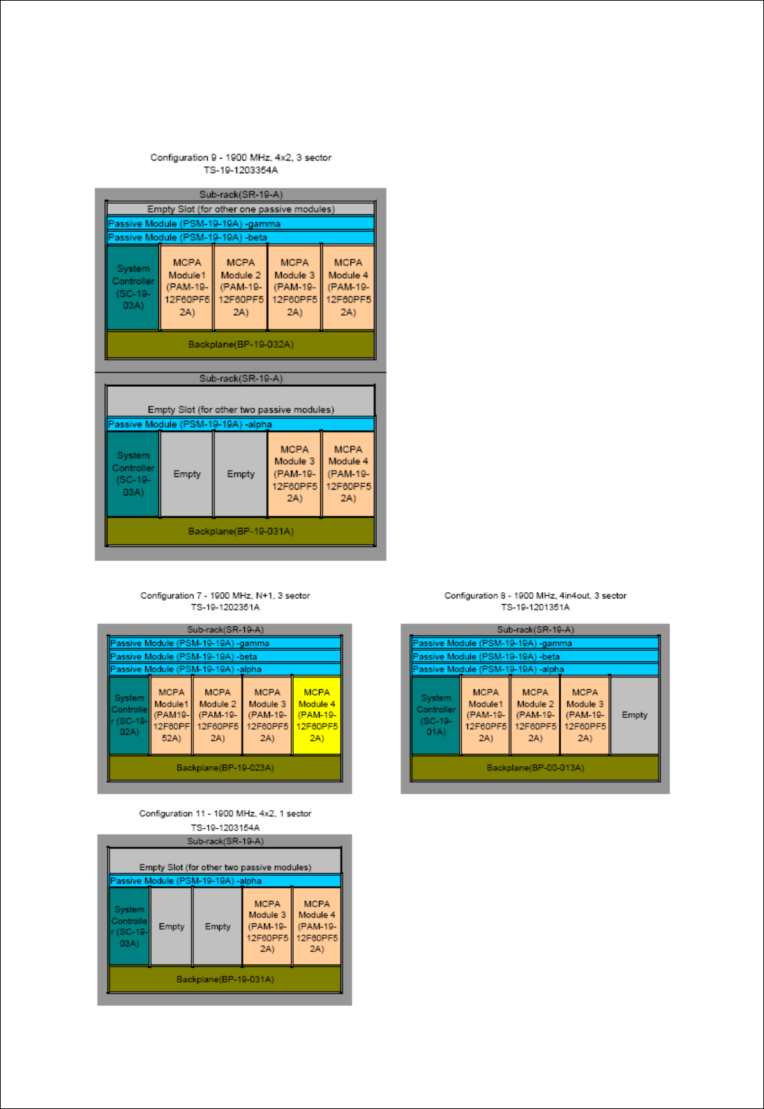
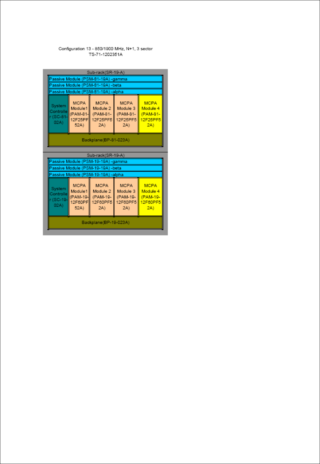
1.2 MODELS COMPLIANCE
According to FCC KDB 754507, FCC test of TS-19-1203354A can meet the FCC requirement
to cover models TS-19-1203354A , TS-19-1202351A, TS-19-1201351A, TS-19-1203154A.
MCPA TBS SYSTEM USER MANUAL
ENU:1-0-0 Copyright Comba Telecom Ltd., March 2009. All rights reserved Page1-14
FCC ID TS-19-1202351A (configuration 7,N+1,3 sectors) can cover the 1900MHz part of
dualband system TS-71-1202351.
End of section

MCPA TBS SYSTEM USER MANUAL
ENU:1-0-0 Copyright Comba Telecom Ltd., March 2009. All rights reserved Page2-15
2 SYSTEM INSTALLATION
2.1 GERNERAL INTRODUCTION
This section introduces the detailed installation procedures of Comba MCPA TBS system. And
before installation, pre-site survey, unpacking inspection and tools preparation are also
included. In order to eliminate the wrong operation and shorten system installation time, this
section and concerned regulation/standard issued by local government should be read
carefully.
For installation procedures of each configuration, it will include contents as following:
Installation Site Requirement
Power Supply Requirement
Temperature and Humidity Requirement
Unpacking and Inspection
Installation Instruction
MCPA TBS SYSTEM USER MANUAL
ENU:1-0-0 Copyright Comba Telecom Ltd., March 2009. All rights reserved Page2-16
2.2 INSTALLATION SITE REQUIREMENT
DANGER
Do not force to install equipment onto the rack which can’t support the weight
of TBS system.
MCPA TBS system is installed on 19’’ rack. The following table is mechanical specifications of
all configurations:
Table 1: Mechanical Specifications of Configurations
Configuration Dimensions(HxWxD,inch) Weight (lbs,approx.)
N+1 26.25x19.00x20.00 251
4 in 4 out 26.25x19.00x20.00 226
4x2, 3 sectors 42.00x19.00x20.00 341
4x2, 1 sector 19.25x19.00x20.00 127
N+1, dualband 52.50x19.00x20.00 502
4x2,dualband 68.25x19.00x20.00 642
Please check the front and rear space of rack to make sure there’s enough clearance space
for easy cabling and quick installation.
MCPA TBS SYSTEM USER MANUAL
ENU:1-0-0 Copyright Comba Telecom Ltd., March 2009. All rights reserved Page2-17
2.3 POWER SUPPLY REQUIREMENT
The power cable selection should rely on the distance between rectifier and Backplane. At the
power terminal of Backplane for MCPA and Cooling Fans, a 27+/-1Vdc is needed.
CAUTION
z The AC or DC power source must be connected to dedicated lightning
arrestor to avoid damage to TBS system in case of lightning.
z All modules of TBS system should be well grounded.
Normally each MCPA needs 35amps (maximal). The voltage and current requirement for each
power terminal (refer to section 2.3.6.6) is as following table:
Table 2: Voltage and Current Requirement
Power Terminal
at Backplane
DC Input
Power (Vdc)
Maximal
Current (A)
Remark
MCPA 1 26-28Vdc 41 6amps (maximal) for System Controller,
Passive Module and cooling fans.
MCPA 2 26-28Vdc 35
MCPA 3 26-28Vdc 35
MCPA 4 26-28Vdc 35
2.3.1 TEMPERATURE AND HUMIDITY REQUIREMENT
MCPA TBS system can operate at -5 to +50 degrees Celsius and 5%-95% relative humidity
ambient. The HVAC requirement is as following:
Table 3: Total HVAC Requirement for MCPA TBS
Subrack
Quantity
MCPA
Quantity
Total HVAC Requirement For Subrack
Assembly and MCPA Module (BTU/hr)
1 3,915
2 7,194
3 10,474
1
4 13753
5 17,669
6 20,948
7 24,228
2
8 27,508
9 31,422
10 34,702
11 37,981
3
12 41,261

MCPA TBS SYSTEM USER MANUAL
ENU:1-0-0 Copyright Comba Telecom Ltd., March 2009. All rights reserved Page2-18
Based on BTS room temperature and relative humidity conditions, a site survey and heat
dissipation evaluation should be processed to make sure whether extra air conditioning is
needed for TBS system. The following table is used for the extra air conditioner selection
Note: It’s recommended that keep the ambient at room temperature.

MCPA TBS SYSTEM USER MANUAL
ENU:1-0-0 Copyright Comba Telecom Ltd., March 2009. All rights reserved Page2-19
2.3.2 UNPACKING AND INSPECTION
TBS system was factory tested, inspected, packed, and delivered to the carrier with utmost
care. When the equipment is delivered to installation site, go through the following unpacking
and inspection process.
1: Carefully unpack and check each package/container against the packing list. For any
shortage, double confirm with carrier. Do not remove items from packing materials until
installation.
2: Visually inspect the enclosure, connectors, and cables for damage caused by improper
shipment. Try to check whether there is evidence for water leakage, bent or wrapped chassis,
loose screws or nuts, or extraneous packing material in the connectors or fans. Inspect male
connectors on modules and harnesses for bent connector pins.
Note: 1. If the equipment is damaged or something is missing, do not accept shipment
from carrier until the carrier's agent endorses a statement of the irregularity on the
face of the carrier's receipt. Without documentary evidence, a claim cannot be
processed.
2. After confirm with carrier and delivery person, if the equipment needs to be
returned to factory, contact with Comba local office (see Appendix B) to get a return
authorization and go through RMA process (Refer to Appendix C)

MCPA TBS SYSTEM USER MANUAL
ENU:1-0-0 Copyright Comba Telecom Ltd., March 2009. All rights reserved Page2-20
2.3.3 INSTALLATION TOOLS REQUIREMENT
Table 4: Tools and Equipment Requirement
Tools/Equipment Function Quantity Provider
Telecommunication installer kit
Tools necessary for cables installation, voltmeter
and safety equipment per installer (such as hard
hat and gloves), etc.
As needed Installer
Wrenches, Screwdrivers
SMA -0.5 to 0.7 N-m wrench
N – 1.3 to 1.7 N-m wrench
7/16 DIN- 25 to 30N-m wrench
Captive Screws- Philip Screwdriver
Hand tools
As needed Installer

MCPA TBS SYSTEM USER MANUAL
ENU:1-0-0 Copyright Comba Telecom Ltd., March 2009. All rights reserved Page3-21
3 SYSTEM POWER ON AND OFF
This section introduces the process of system power on and off process. And the introduction
of visual controls and indicators of MCPA and System Controller is used to check whether the
mechanical installation is proper.
The contents are as following:
Controls and Indicators of System Controller and MCPA module
System power on and off
MCPA TBS SYSTEM USER MANUAL
ENU:1-0-0 Copyright Comba Telecom Ltd., March 2009. All rights reserved Page3-22
3.1 CONTROLS AND INDICATORS
Before system initial startup, to understand the controls and indicators is very important for
operator. TBS system provides Circuit Breaker and Enable Switch and some LED indicators
on the front panel of MCPA Module and System Controller.
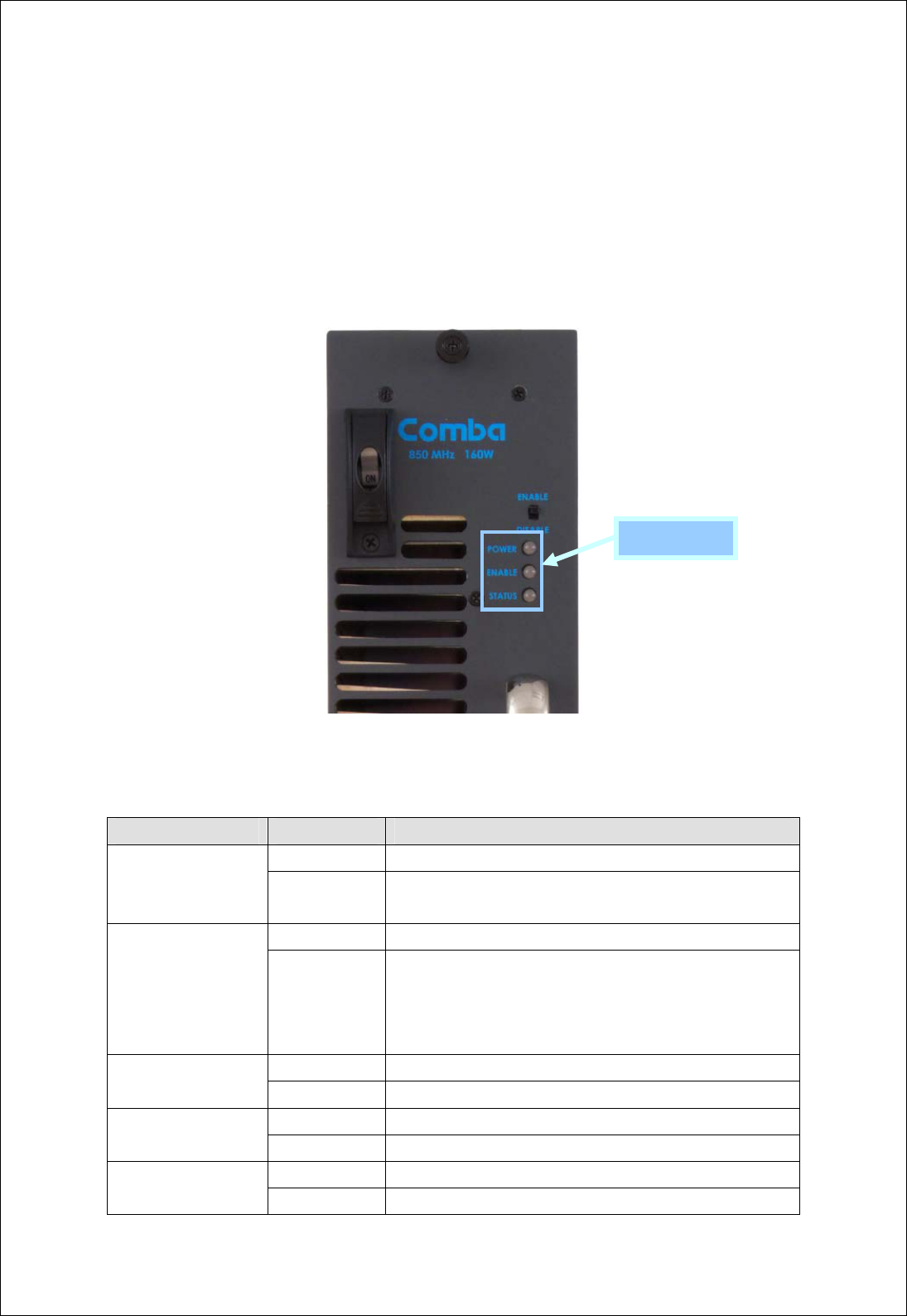
3.1.1 MCPA CONTROL AND INDICATOR
On the Front panel of MCPA Module, the controls and LED indicators are showed in following
figure. The function is explained in table 1.
Figure 1: Controls and Indicators on Front Panel of MCPA Module
Table 5: Functions of Controls and Indicators on MCPA Module
Control/Indicators Status Functions
ON Provide DC power to MCPA
Circuit Breaker
OFF
Shut the DC power to MCPA. Before plug out MCPA, the Circuit
Breaker should be push to OFF status
ENABLE Turn on RF output from MCPA. The Enable LED is in green color
Enable Switch
DISABLE
Turn off RF output power from MCPA, but System Controller can
still detect MCPA and feedback the status. Before turn off Circuit
Breaker, the switch had better to turn to DISABLE status. The
Enable LED is in black color
Green 27VDC power supply is normal
Power LED
Black (OFF) 27Vdc power supply is not available.
Green The PA is at ENABLE status
Enable LED
Black (OFF) The PA is at DISABLE status
Green MCPA is in normal operation, no alarms Status LED
Amber MCPA is abnormal and there should be some Minor Alarm
LED Indicators
MCPA TBS SYSTEM USER MANUAL
ENU:1-0-0 Copyright Comba Telecom Ltd., March 2009. All rights reserved Page3-23
Red MCPA is abnormal and there should be some Major alarm
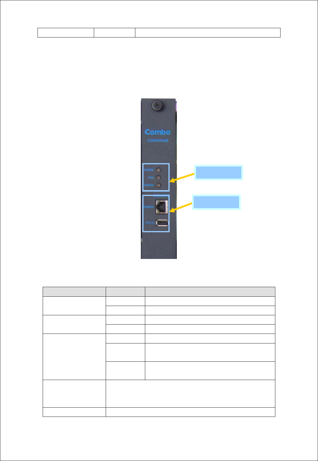
3.1.2 CONTROL MODULE CONTROL AND INDICATORS
Except the status of MCPA can be visually monitored and controlled, the front panel of System
Controller also have LED indicators and interfaces for system diagnosis and commissioning.
The front panel is shown as following. The function and purpose are explained in table 3-x.
Figure 2: Indicators and Interface on Front Panel of System Controller
Table 6: Functions of Indicators and interfaces of System Controller
Indicators/Interfaces Status Functions
Green +27DC power to the system is normal
POWER LED
Black (OFF) +27Vdc power supply is unavailable.
Green All 6 cooling fans are in normal running.
FAN LED
Orange Minor Alarm: Cooling Fan is abnormal.
Green The system is in normal operation, no alarms.
Orange
The system is abnormal and there should be some minor
alarm.
Status LED
Red
The system is abnormal and there should be some major
alarm.
Ethernet Port
Used for local PC connection for commissioning and monitoring. This port is
also reversed to connect to BTS controller for TBS system remote
commissioning and monitoring.
USB Port Factory use
LED Indicators
PC Interface
MCPA TBS SYSTEM USER MANUAL
ENU:1-0-0 Copyright Comba Telecom Ltd., March 2009. All rights reserved Page3-24
3.2 SYSTEM DC POWER ON AND OFF PROCEDURES
The following procedures are for TBS system DC power on and off.
1. Test the antenna system and ensure the echo loss within working frequency is less than
-14dB (VSWR<1.5).
DANGER
z Do not turn on the power supply from Rectifier.
z Do not turn on input power from BTS.
2. Visually inspect the power connection within the equipment. Ensure that the power cable is
correctly and securely connected.
3. Check grounding connection and verify that the ground resistance is less than 5Ω.
4. Check all circuit breaker of MCPA modules have been set to OFF. And Enable Switch has
been set to DISABLE position.
5. Before turn on MCPA Module, use power meter to test the input composite power from BTS
is not more than 43dBm.
WARNING
z Do not input >43dBm power into MCPA.
z Before applying power from BTS, please make sure the MCPA has been
properly terminated at 50 ohms.
6. Turn on the power from Rectifier and verify the input voltage for MCPA is in the range of
26-28Vdc on the power terminals at the back of Backplane. After power on, the cooling fans
will run and LED indicators on System Controller front panel will become stable without red or
amber color.
7. Turn on power of MCPA one by one (set Circuit Breaker to ON and push Enable Switch to
ENABLE). Check the LED indicators and there’s not red or amber color.
Note: After this step, all LED indicator status on the front panel of System Controller and
MCPA modules are in normal color (refer to table 21 & 22). If there are any alarms,
please contact with field engineer.
8. Push Enable Switch to DISABLE and push Circuit Breaker to OFF. Turn off power supply to
MCPA and rectifier. Write down installation record and check with field engineer for system
commissioning.

MCPA TBS SYSTEM USER MANUAL
ENU:1-0-0 Copyright Comba Telecom Ltd., March 2009. All rights reserved Page3-25
Note: After this step 7, if the system needs to be put into service, please go to ‘Comba
MCPA TBS system operation and maintenance manual’ Section 2& 3.
End of section
MCPA TBS SYSTEM USER MANUAL
ENU:1-0-0 Copyright Comba Telecom Ltd., March 2009. All rights reserved Page4-26
4 APPENDICES
4.1 APPENDIX A: SUGGESTION FOR THE DOCUMENT
Customer Information:
Name
Title
Company
Date
Address
Telephone Number
Customer Comments:
Equipment title
ENU
Page number
Paragraph number
Line number
Figure number
Details of inaccuracies
Other comments
Contact points:
E-mail: document@Comba-telecom.com
FAX: +852-21166055

MCPA TBS SYSTEM USER MANUAL
ENU:1-0-0 Copyright Comba Telecom Ltd., March 2009. All rights reserved Page4-27
4.2 APPENDIX B: SERVICE POLICY AND RETURN OF EQUIPMENT
The repair of individual units and modules of this equipment is not considered practicable
without factory facilities. It is, therefore, the policy of Comba whereby faulty units or modules
are returned to the local agent for repair. To enable an efficient, prompt after sales service to
be provided for the diagnosis, repair and return of any faulty equipment, please comply with
the following requirements.
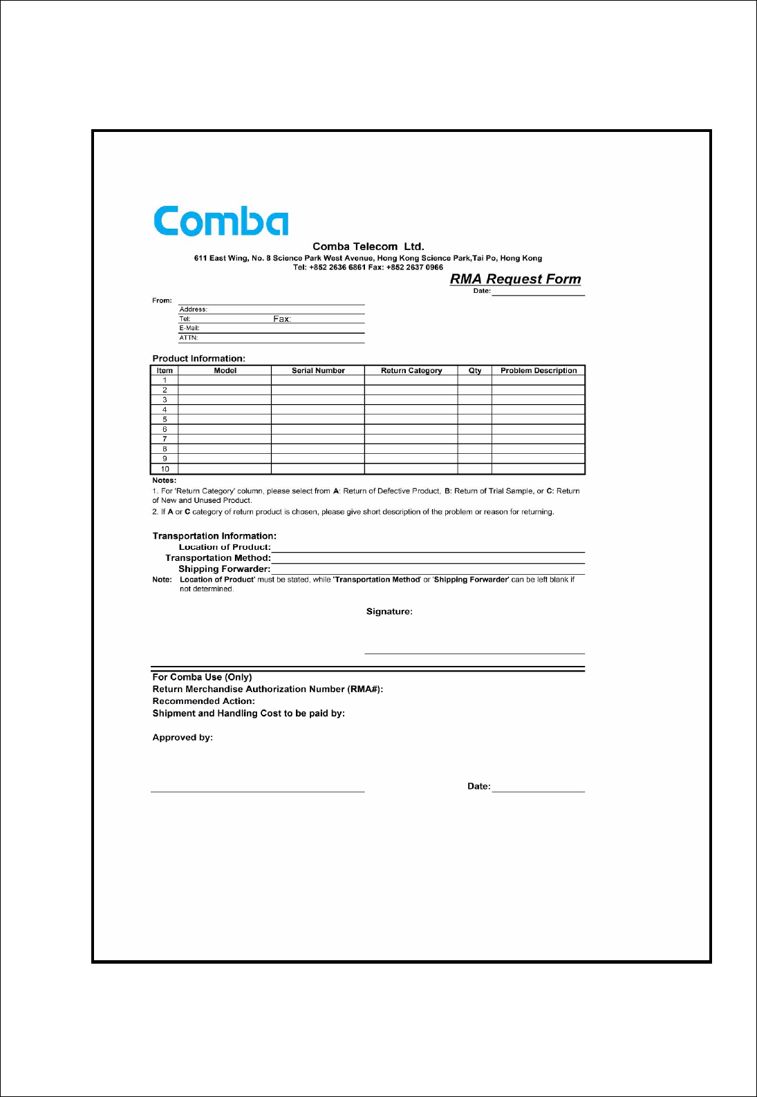
Items to be sent for repair should be packaged so as to provide both electrostatic and physical
protection and a Repair Material Authorization (RMA) should be completed giving the required
information. A sample RMA form is provided in Appendix C.
This request must be included with the item for repair, items for repair should be sent to the
nearest Comba office:
COMBA TELECOM LTD.
USA Office
Address: 2390 Bering Drive, San Jose, CA 95131, USA
Tel: +1 408 526 0180
Fax: +1 408 526 0181
Email: combausa@comba-telecom.com
Hong Kong Office
Address: 611 East Wing, No. 8 Science Park West Avenue, Hong Kong Science Park,
Tai Po, Hong Kong.
Tel: +852 2636 6861
Fax: +852 2637 0966
Email: combahk@comba-telecom.com
Singapore Office
Address: 865 Mountbatten Road, Katong SC #05-43, Singapore 437844
Tel: + 65 6345 4908
Fax: + 65 6345 1186
Email: combasg@comba-telecom.com
Thailand Office
Address: 3rd Floor, T. Shinawatra Building, 94 Sukhumvit Soi 23, Sukhumvit Road,
Klongtoeynua, Wattana, Bangkok 10110
Tel: +66 2664 3440
Fax: +66 2664 3442
India Office
Address: Suite No. 2, E-172, TSH House, Greater Kailash – I, New Delhi – 110 048, India
Tel: + 91 11 5173 9997 / 8
Fax: + 91 11 5173 9996

MCPA TBS SYSTEM USER MANUAL
ENU:1-0-0 Copyright Comba Telecom Ltd., March 2009. All rights reserved Page4-28
Email: comba@comba-telecom.com
Sweden Office
Address: Gustavslundsvagen 147, S- 167 51 Bromma, Stockholm, Sweden
Tel: +46 8 25 38 70
Fax: +46 8 25 38 71
Email: info@comba-telecom.se
Brazil Sales Office
Avenida Engenheiro Luiz Carlos Berrini 1297, cj 122, sala 03 04571-090 São Paulo, Brazil
Tel: +55 11 55050549
Fax: +55 11 55050549 ext 7
China Office
Address: No.10, Shenzhou Road, Guangzhou Science City, Guangzhou, China
Tel: + 86 20 2839 0000
Fax: + 86 20 2839 0136
Email: combagz@comba-telecom.com
MCPA TBS SYSTEM USER MANUAL
ENU:1-0-0 Copyright Comba Telecom Ltd., March 2009. All rights reserved Page4-29
4.3 APPENDIX C: RMA (RETURN MATERIAL AUTHORIZATION)
FORM
End of section
End of Document