Comeup 882756 Wireless Remote Control User Manual
Comeup Industries Inc. Wireless Remote Control
Comeup >
User Manual

Wireless Receiver Model NO:882756
I.Specifications
1. Transmission range: 15 ~ 27 m (50 ~ 90 ft)
2. Receiver operation voltage: 8 - 24 V
3. Protection: IP 66
4. Operating temperature range: -20°C ~ +65°C
III Operation
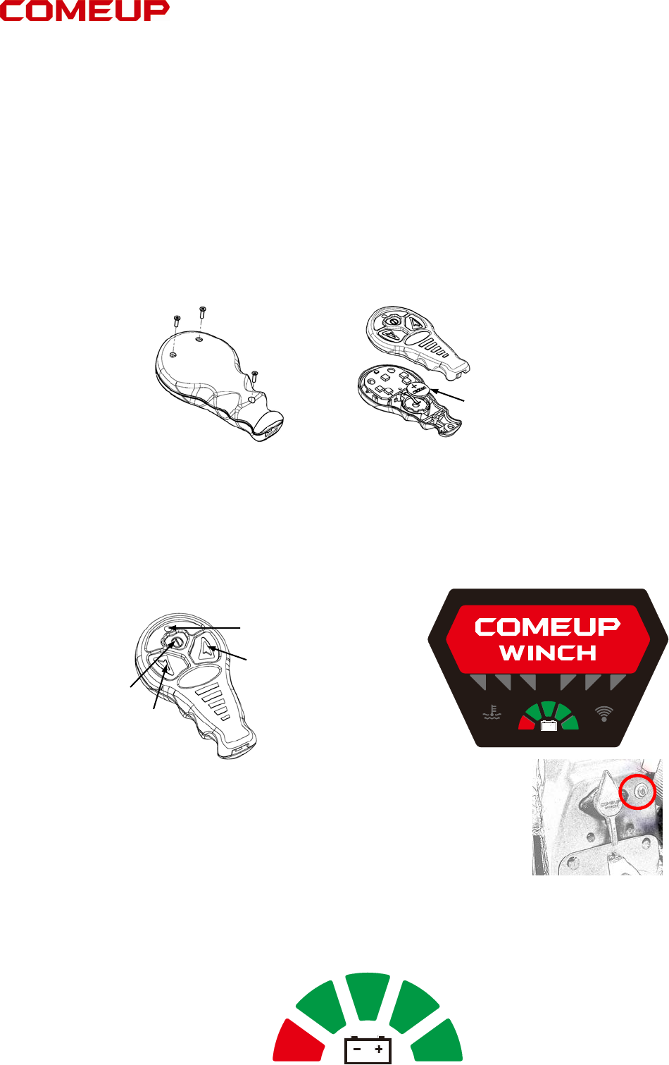
1. Install and replace battery.
a. Remove the three screws from the wireless transmitter.
b. Separate the top section and remove the old battery and dispose it.
c. Insert new battery and join the top section with the bottom section.
d. Make sure to fasten the three screws.
2. Start
a. Attach the red(+) and black(-) battery leads to battery set on the vehicle. Press the
Cutout switch , then the buzzer alarms for decoding and all LED flash.
b. Hold the Power Button of the transmitter for about 5 seconds,then the LED Indicator
lights permanently.
c. Hold either Cable In Button or Cable Out Button of the transmitter, then the buzzer
alarms long sound lasting for 5 seconds.
d. Only flashing LED on Logo and Vehicle Battery Life..
e. The wireless remote control is now workable.
1. Cutout Switch
Your Seal Gen2 9.5i/9.5si /9.5rsi Winches have a cutout switch to
activate or deactivate the winch.
The cutout switch on the Seal Gen2 9.5rsi models also deactivate the
wireless receiver to prevent parasitic draw.
2. Vehicle Battery Life
Your Seal Gen2 9.5i/9.5si/9.5rsi Winches indicate the status of vehicle battery level.
The fan-shaped out Vehicle Battery Level indicate the status of your vehicle battery level by
locating block and changing color。 If your battery level at an extreme low level, your must
charge the battery immediately. The minimum requirement for a 12 V vehicle battery is 650
cold cranking amps。
1st Icon (Green): Fully charged about 12V level
2nd Icon (Green): Fair charged about 11V
3rd Icon (Green): Fair charged about 10 V
4th Icon (Green): Low charged about 9V
5th Icon (Red): extreme low below 8V
Wireless Remote Module
Lithium Battery: CR2032 (3V)
Cable OUT
Cable IN
Power Button
LED Indicator
IDB
1

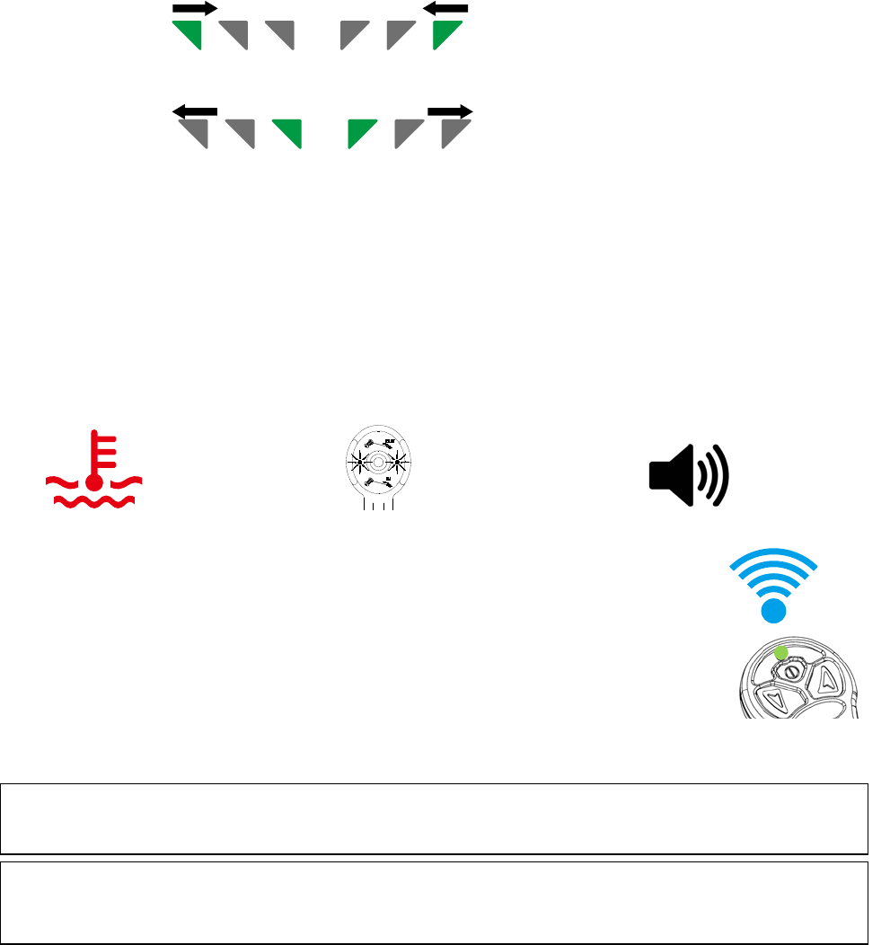
3. Cable IN/OUT Direction Indicators:
The green triangle icons on the Intelligence Dashboard (IDS) for your Seal Gen2 9.5rsi will
light sequentially to indicate the rope winding direction。
3.1 Cable IN: The green triangle icons moved from the outside toward the center indicate the
rope winding-in direction.
3.2 Cable OUT: The green triangles icons moved from the center toward the outside indicate
the rope winding-out direction.
3.3 The green triangles icons will turn to red triangles if the motor is over-heating, but the
direction remains unchanged.
4. Thermal Protection
There are three kinds of thermal protection function to protect the motor and control from
damaged or personal injury:
4.1 Temperature warning: The flashing red temperature icon on the intelligence Dashboard
(IDB) of your Seal Gen2 9.5rsi winch indicates the motor is over-heating.
4.2 Handheld Remote Warning: The two green LED indicators on the wired remote control
will change to the red if the motor is over-heating.
4.3 Buzzer warning:, The Seal Gen 2 9.5rs/9.5rsi/12.5rs include an audible buzzer alarm that
alerts if the motor is over-heating.
Temperature Warning Handheld Remote Warning Buzzer warning
5. Wireless Remote Control Icon
5.1 The intelligence Dashboard (IDB) of your Seal Gen2 9.5rsi includes a
blue wireless signal icon that is continuously illuminated to confirm the
wireless remote is paired with thewinch。
5.2 The solid green LED indicators on the wireless transmitter indicates
goodsignal strength,but a flashing red LED indicates a weak signal。
6. Wireless transmitter’s battery life
The solid green LED indicators on the wireless transmitter show a fair internal
battery life, but a flashing green LED indicator indicates a low battery level。 The battery should
be replaced immediately if a weak or no signal status found。
FEDERAL COMMUNICATIONS COMMISSION INTERFERENCE STATEMENT
This equipment has been tested and found to comply with the limits for a Class B digital device, pursuant to part 15 of the FCC Rules。
These limits are designed to provide reasonable protection against harmful interference in a residential installation. This equipment
generates uses and can radiate radio frequency energy and, if not installed and used in accordance with the instructions, may cause
harmful interference to radio communications。
However, there is no guarantee that interference will not occur in a particular installation. If this equipment does cause harmful
interference to radio or television reception, which can be determined by turning the equipment off and on, the user is encouraged to try
to correct the interference by one or more of the following measures:
- Reorient or relocate the receiving antenna.
- Increase the separation between the equipment and receiver.
- Connect the equipment into an outlet on a circuit different from that to which the receiver is connected.
- Consult the dealer or an experienced radio / TV technician for help.
CAUTION:
Any changes or modifications not expressly approved by the grantee of this device could void the user's authority to
operate the equipment。
CE Mark Warning
• This is a Class B product, in a domestic environment, this product may cause radio interference, in which case the user may be
required to take adequate measures。
FCC and Industry Canada (IC) Warning:
• This device complies with Part 15 of the FCC Rules。 Operation is subject to the following two conditions: (1) This device may not
cause harmful interference, and (2) this device must accept any interference received, including interference that may cause
undesired operation。
2