CommScope of North Carolina AIRBRIDGE-AP UNII Transmitter User Manual Users guide
CommScope, Inc. of North Carolina UNII Transmitter Users guide
Users guide

33
P.O. Box 1729
Hickory, NC 28603
Phone: (800) 982-1708 or (828) 324-2200
Fax: (828) 431-2504 (Domestic Sales)
Fax: (828) 323-4989 (International Sales)
Fax: (828) 328-3400 (Customer Service)
Version 2, 19 October 2005

32
Appendix D: Firmware Upgrades
The most recent version of firmware may be made available by contacting CommScope.
MICROCONTROLLER FIRMWARE UPGRADE
To download a new firmware from a computer to the AP microcontroller, it is necessary to have a TFTP
client capable of sending a binary file. The parameters to send the firmware are:
Target filename: APP
Transfer mode: binary (octet)
Target port: 70
Block size: 512
Note: The file to be downloaded must be the .bin
(binary) image, not the hex version! File size should
be 69,376 bytes.
ETHERNET CONTROLLER FIRMWARE UPGRADE
To download a new firmware from a computer to the AP Ethernet interface controller, it is necessary to
have a TFTP client capable of sending a binary file. The parameters to send the firmware are:
Target filename: X1
Transfer mode: binary (octet)
Target port: 69
Block size: 512
Note: The file to be downloaded must be the .ROM
(binary) image, not the hex version! File size should be
32768 or 65536 bytes.
31
C.5 Private IP networks and the Internet
If your network is not connected to the Internet and there are no plans to make such a connection, you
may use any IP address you wish. However, if you are not connected to the Internet and have plans to
connect to the Internet, or you are connected to the Internet and want to operate your SNMP interface on
an Intranet, you should use one of the following sub-networks for your network:
Class A 10.x.x.x
Class B 172.16.x.x
Class C 192.168.0.x
These network numbers have been reserved for such networks. If you have any questions about IP
address assignment ask your Network Administrator.

30
Appendix C: IP Addresses, Netmask, Etc.
C.1 IP Addressing
An IP address is a 32-bit value, divided into four octets of eight bits each. The standard representation is
four decimal numbers (in the range of 0...255), divided by dots. Example: 192.2.1.123. This is called
decimal-dot notation. The IP address is divided into two parts: a network and a host part. To support
different needs, three “network classes“ have been defined. Depending on the network class, the last
one, two or three bytes define the host, while the remaining part defines the network. In the following
text, ‘x’ stands for the host part of the IP address:
Class A network
IP address 1.x.x.x to 127.x.x.x
Only 127 different networks of this class exist. These have a very large number of potential
connected devices (up to 16777216).
Example: 10.0.0.1, (network 10, host 0.0.1)
Class B network
IP address 128.0.x.x to 191.255.x.x
These networks are used for large company networks. Every network can consist of up to
65534 devices.
Example: 172.1.3.2 (network 172.1, host 3.2)
Class C network
IP address 192.0.0.x to 223.255.255.x
These network addresses are most common. Most smaller companies’ networks are class C
networks. These networks can consist of a maximum number of 254 hosts.
Example: 192.7.1.9 (network 192.7.1, host 9)
Class D network
IP address 224.x.x.x to 239.x.x.x
These addresses are used as multicast addresses.
Example: 224.7.1.9 (network 224, host 7.1.9)
Class E network
IP address 240.x.x.x to 254.x.x.x
These addresses are reserved.
C.2 Network Address
An address with all host bits set to "0" is used to address the network as a whole (in routing
entries, for example).
C.3 Broadcast Address
An address with the host part bits all set to “1“ is the broadcast address, meaning “for every station.“
Network and Broadcast addresses must not be used as a host address (e.g. 192.168.0.0 identifies the
entire network, 192.168.0.255 identifies the broadcast address).
C.4 IP Netmask
The netmask is used to divide the IP address differently from the standard defined by the classes A, B, C.
By entering a netmask, it is possible to define how many bits from the IP address are to be taken as the
network part and how many bits are to be taken as the host part.
Standard IP Network Netmask: Class A 8 (network) 24 (host) 255.0.0.0 (mask)
Class B 16 (network) 16 (host) 255.255.0.0 (mask)
Class C 24 (network) 8 (host) 255.255.255.0 (mask)
29
Appendix B: Setting Auto Mute Threshold
The upstream mute threshold is limited by the SNR. At lower levels, the noise level becomes closer to
the signal level. Therefore, as the threshold level is dropped, the muting will start to be activated by the
noise. This happens closer to the signal level when the signal is lower.
The upstream noise level is proportional to the receive gain setting. With a high enough gain and a low
enough mute threshold setting, the noise may be high enough to prevent the detection circuitry in the AP
from muting. To ensure this does not happen, the threshold should be set no lower than 30 dB below the
gain setting (i.e. Gain - 30 dB). So for gains of 36/46/56/66/76 dB, the threshold should be set no lower
than 10/16/26/36/46 dBmV. This puts a lower limit on the threshold for a given gain setting.
The upper limit of the threshold is based on the upstream signal level. While a setting of 45 dBmV is
guaranteed to work with an output level of 45 dBmV, the signal level may change due to CATV plant gain
variations. Note that upstream gain variations of the RF link have little effect since the CMTS causes the
CM to compensate for upstream gain changes. So it would be recommended to set the threshold at least
3 or 4 dB below the desired output.
For example, for a gain of 55 dB and an output level of 35 dBmV, the threshold should be set to between
25 (55 - 30) and 31 dBmV (35 - 4).

28
Appendix A: Specifications
AP5800 Specifications
DOWNSTREAM
Transmit RF frequency band 5799 to 5823 MHz
Transmit EIRP +15 to +28 dBm rated maximum
IF input frequency range 91 to 857 MHz (channel center frequencies)
IF input level range 0 to +20 dBmV per channel
Downstream modulation One 6 MHz 64QAM or 256QAM channel, typical
Downstream flatness 1 dB p-p over 5 MHz, typical
UPSTREAM
Receive RF frequency band 5727 to 5751 MHz
Noise figure (at RF connector) 6 dB max at max gain
Image rejection 90 dB minimum
IF output frequency band 18 to 42 MHz
Gain range 36 ± 2 dB to 76 ± 2 dB at mid band
IF level 17 to 50 dBmV
Gain flatness (frequency response) ±0.5 dB over 3.2 MHz, 2.5 dB p-p full band
Spectral inversion No spectral inversion
Return loss (IF) 13 dB min: 5 to 42 MHz and 88 to 860 MHz
GENERAL
Upstream ingress mitigation Automatic upstream IF mute
Upstream gain control
Upstream mute control via remote access
Upstream power detector
IF connector F female, 75 ohms, SCTE compliant
IF connector torque 20 in-lb
Power requirements 35 to 90 VAC, 60 Hz
Power consumption 27 W maximum
Management Remote and local status monitoring and control
SNMPv1.1 remote access
RS232 command line local interface
Operating temperature range -40 to +60 °C
Antenna Integrated (“Normal” configuration), 60° horizontal and 30°
vertical beamwidth
EMC compliance FCC CFR 47, Part 15, Subparts A and B
FCC Part 15, Subpart E, Section 15.401
FCC 47 CFR, Part 76, Subpart K (76.605)
Configurations Strand mount, utility pole mount, pipe mount
(options STRAND, POLE, PIPE)
Size 60.2 x 22.3 x 12.4 cm (23.7” x 8.8” x 4.9”)
Weight 7.1 kg (15.6 lbs)
Specifications subject to change without notice.
27
5.6.4 Community Strings
The SNMP read and write communities are user definable strings. SNMP community strings are
like a user ID or password that allows access to a device's statistics. An SNMP Manager sends
the community string along with all SNMP requests. If the community string is correct, the device
responds with the requested information. If the community string is incorrect, the device simply
discards the request and does not respond. Refer to Section 4.6.6 for information on viewing and
changing the SNMP community strings.
26
which you are working. Once there is at least one entry in the ARP table, use the commands shown
above to ARP an IP address to the AP interface.
b) Open a Telnet connection to port number 1. This connection will fail, but the AP Ethernet interface will
change its IP address to the IP address assigned to the MAC address used by the arp –s command.
The following example opens a Telnet connection to IP address 10.10.10.11 port 1:
telnet 10.10.10.11 1
c) Open a Telnet connection to port 23 and set all required parameters. The following example opens a
Telnet connection to IP address 10.10.10.11 port 23:
telnet 10.10.10.11
d) When the Telnet connection is established, navigate through the menus until the Ethernet Settings
menu is reached (See Section 4.5 for navigating menus). Enter Ethernet IP address, netmask and
gateway. Refer to Section 4.6.6 for further information on the Ethernet parameters available. The
temporary IP address set in the above procedure is cleared after every power cycle of the AP Ethernet
interface. Be sure to enter configuration data as described in Section 4.6.6 to make the change
permanent! The AP Ethernet interface configuration is stored in nonvolatile memory and is retained
without AC power. The configuration can be changed any time.
5.5 Telnet
The steps required to enable Telnet operation are as follows:
1. Configure the Network Interface as described in Section 5.4 above.
2. Login remotely using a shell, terminal, browser, or Telnet application window, refer to Section 4 for
further information on using the command line interface via Telnet.
5.6 SNMP
5.6.1 Operation
The steps required to enable SNMP operation are as follows:
1. Configure the Network Interface as described in Section 5.4 above.
2. Configure SNMP settings using the command line interface (as described in Section 4.6.6)
either locally or remotely via Telnet.
The steps required for configuring an SNMP Management Station to manage an SNMP enabled
access point are as follows:
1. Load and compile the 2 supplied MIB files (supplied on disk) into the MIB database on the
Management station. The supplied MIB files are described in Section 5.6.2.
2. Refer to the documentation that accompanied the Management station for information on
Compiling Private MIB files, adding devices to manage, etc.
5.6.2 Supplied MIBs
There are 2 Private MIB files that are used by the SNMP agent. These files are provided on disk.
These files must be compiled into the MIB used in the SNMP management station that will be
managing the AP unit. The two files must be added in order. The file named csGlobal.mib must
be added first followed by the file named csAP5800.mib. These MIB files have been tested with
SNMPc V5.0 from Castlerock software, MG-SOFT MIB Browser Professional, and with HP
OpenView from Hewlett Packard.
5.6.3 Configuration
SNMP can be enabled or disabled via the AP interface (locally or remotely), refer to section 4 for
details.

25
5.0 Remote Access
5.1 Description
Remote access of the AP is available through Telnet and SNMPv1. TFTP is available for remote
firmware upgrades.
5.2 Supported Network Protocols
The AP Ethernet interface uses several TCP/IP protocols for network communication. The supported
standards are ARP, UDP, TCP, ICMP, Telnet, TFTP and SNMP. The electrical interface is fully compliant
with IEEE 802.3 10-Base-T Ethernet and
100BASE-TX (auto-sensing)
.
5.3 Network Hardware Address
The hardware address of the AP Ethernet interface is printed on a label on the unit. This address is
unique for each unit and consists of 6 two digit hexadecimal values. The hardware address can also
be obtained via the interface (See Section 4.6.6). An example address is: 00:20:4A:52:3A:34
5.4 Assigning an IP Address
The unit's IP address must be configured before a network connection is available. You have the
following options for assigning an IP to the unit:
1) Local Interface
2) DHCP
3) ARP and Telnet
LOCAL INTERFACE
The unit's Ethernet IP address, netmask, and gateway IP address can be assigned via the local interface,
refer to section 4.6.6 for further information on configuring available Ethernet parameters.
DHCP
The unit ships with a default IP address of 0.0.0.0, which automatically enables DHCP. Provided a DHCP
server exists on the network, it will provide the unit with an IP address, gateway address, and subnet
mask when the unit boots up or the Ethernet interface is renewed (See Section 4.6.6 for enabling DHCP
mode and renewing the Ethernet interface).
ARP AND TELNET
The following procedure sets a temporary IP address so that setup over the network can be
done:
a) Set a static ARP route with the desired IP address using the hardware address of the AP
Ethernet interface, which is printed on a label on the module. In Windows, a static route can be
set from the DOS prompt using the ARP command. The following example command sets a
default route to the IP address 10.10.10.11 via hardware address 00-20-4A-52-3A-34:
arp -s 10.10.10.11 00-20-4A-52-3A-34
-The IP address 10.10.10.11 is used here as an example only. This address must be replaced by
one that is valid for the target network in order for this procedure to function properly. The IP address
assigned must be on the same subnet as the computer doing the initial configuration. A network
administrator can supply the proper values for these parameters. Refer to Appendix C, IP Addresses,
Netmask, etc. for more information on IP address selection.
-In order for the ARP command to work in Windows, the ARP table on the PC must have at least
one IP address defined other than its own. Type “arp –a” at the DOS command prompt to verify that
there is at least one entry in the ARP table. If there is no other entry besides the local machine, ping
another IP machine on your network to build the table. This has to be a host other than the machine on

24
Enter the new IP address or press ENTER to use the current value.
Renew Ethernet Interface In order to activate any changes to the Ethernet settings, the interface needs
to be restarted. To Renew the Ethernet Interface, type “4”. The prompt will change to:
Renew Ethernet Interface [Y/N](N)>_
Enter Yes to renew the Ethernet interface or enter No or press ENTER to abort.
SNMP Enable This setting allows the user to enable Simple Network Management Protocol. To change
the SNMP Enable, type “5”. The prompt will change to:
SNMP Enable[0 disable, 1 enable](1)>_
Enter the new values or press ENTER to use the current value.
SNMP Manager IP Address This address is used to send SNMP traps. To change the SNMP Manager
IP address, type “6”. The prompt will change to:
SNMP Manager IP Address [] (10.10.10.10)>_
Enter the new IP address or press ENTER to use the current value.
SNMP Read Community To change the SNMP read community string, type “7”. The prompt will change
to:
SNMP Read Community [32 chars max] (public)>_
Enter the new community string or press ENTER to use the current value.
SNMP Write Community To change the SNMP write community string, type “8”. The prompt will change
to:
SNMP Write Community [32 chars max] (private)>_
Enter the new community string or press ENTER to use the current value.

23
gain cannot be set by the user.
4.6.6 Ethernet Settings
The Ethernet Settings Menu provides access to the Ethernet settings and options. To access this
menu from the Main Menu, type “6” to display the Ethernet Settings Menu. Note: These settings
would normally come from your Network Administrator or IT Department.
Figure 4.10: Ethernet Settings Menu
*** AirBridge AP Ethernet Settings ***
MAC Address 00:20:4A:52:3A:34
1)IP Address 10.10.10.11
2)Netmask 255.255.255.0
3)Gateway IP Address 10.10.10.10
4)Renew Ethernet Interface
5)SNMP Enable Enabled
6)SNMP Manager IP Address 10.10.10.10
7)SNMP Read Community public
8)SNMP Write Community private
X)Exit
ENTER)Refresh
Select>_
MAC Address This address is unique for each unit and consists of 6 two digit hexadecimal values.
IP Address The IP address must be set to a unique value in your network. Refer to Appendix C if you
are not familiar with IP addresses. If set to 0.0.0.0, DHCP mode is automatically enabled. Provided a
DHCP server exists on the network, it will provide the unit with an IP address, gateway address, and
subnet mask when the unit boots up. To change the IP address, type “1”. The prompt will change to:
IP Address [] (10.10.10.11)>_
Enter the new IP address or press ENTER to use the current value.
Netmask A netmask defines how many bits from the IP address are to be taken as the network part and
how many bits are to be taken as the host part (Reminder: standard class A 8/24 (net/host), class B
16/16, class C 24/8 bits). The netmask is shown in standard format “255.255.xxx.xxx”. To change the
netmask, type “2”. The prompt will change to:
Netmask [] (255.255.255.0)>_
Enter the new netmask or press ENTER to use the current value.
Gateway IP Address The router/gateway address is needed to communicate to other LAN segments.
The default gateway must be set to address the router that connects these segments. This address must
be within the local network. If in doubt, your network administrator should be consulted. To change the
Gateway IP address, type “3”. The prompt will change to:
Gateway IP Address [] (10.10.10.10)>_

22
From your terminal emulator program send the modulator file using Xmodem protocol with CRC or
press CONTROL-D to abort. In HyperTerminal, you send the modulator file by going to “Transfer”
“Send File…” Upon successful upgrade, the unit will reset and the password> prompt will be
displayed. In general, the firmware and modulator upgrades are independent unless it is otherwise
indicated. That means that one may be upgraded without changing the other.
Reset Unit The reset menu option does a software reset of the AP (i.e. reboot). To reset the unit, type
“5”. The prompt will change to:
Reset Unit [Y/N](N)>_
Enter Yes to reset the unit or enter No or press ENTER to abort.
Load Factory Defaults
The Load Factory Defaults allows the user to put all the radio settings into a
known state. The settings are:
Downstream Settings
RF Frequency (MHz) 5802.000
Output EIRP (dBm) 28.0
Downstream Modulation 256QAM
Downstream Interleaver 16,8
Output Mute Unmuted
Upstream Settings
Gain (dB) 50.0
Output Mute Muted (Manual)
Output Auto Mute Threshold (dBmV) 30.0
Output Alarm Threshold (dBmV) 50.0
Output Alarm Threshold Enable Disabled
General Settings
Change Password [no password]
User Message [no message]
Ethernet Settings
IP Address 0.0.0.0
SNMP Enable Disabled
SNMP Manager IP Address 192.168.0.1
SNMP Read Community public
SNMP Write Community private
To load the factory defaults, type “6”. The local interface prompt will change to:
Load Factory Defaults [Y/N](N)>_
Enter Y to load factory defaults or press ENTER to select No.
Antenna Gain (dB) The antenna gain line shows the current antenna gain. It is factory set to 12 dBi for
the internal antenna. These values reflect the effective gain and include cable and radome loss. The

21
3)Upgrade Firmware 2.16b
4)Upgrade Modulator 0.22
5)Reset Unit
6) Load Factory Defaults
Antenna Gain (dB) 12.0
X)Exit
ENTER)Refresh
Select>_
Change Password The access password is user settable and restricts unauthorized access to the AP
interface. To change the access password, type “1”. The prompt will change to:
Change Password [0 = empty string](***)>_
Enter the new password or press ENTER to use the current value.
If a new password is entered, the user will be prompted to re-enter the same password (for verification).
Confirm Password [0 = empty string](***)>_
User Message The user message is a user definable string that is displayed at the password menu.
To change the user message, type “2”. The prompt will change to:
User Message [32 chars max](112 Pine Street)>_
Enter the new message or press ENTER to use the current value.
Upgrade Firmware The upgrade firmware menu option allows upgrading the application and bootloader
flash areas via the interface. Remote upgrades cannot be done through a Telnet session but can be
accomplished via TFTP over Ethernet. Note: Ethernet controller firmware can only be upgraded by
TFTP. See Appendix D for information on upgrading firmware via TFTP. To upgrade the firmware, type
“3”. The prompt will change to:
Upgrade Firmware [Y/N](N)>_
Upon selecting Yes, the unit will wait for the firmware image. The prompt will change to:
Waiting For Data [Ctrl-D to Abort]...>_
From your terminal emulator program send the firmware file using Xmodem protocol with CRC or
press CONTROL-D to abort. In HyperTerminal, you send the firmware file by going to “Transfer”
“Send File…” Upon successful upgrade, the unit will reset and the password> prompt will be
displayed.
Upgrade Modulator The Upgrade Modulator menu option allows upgrading the firmware for the QAM
modulator via the local interface. Remote upgrades cannot be done through a Telnet session but can be
accomplished via TFTP over Ethernet. To upgrade the modulator, type “4”. The local interface prompt
will change to:
Upgrade Modulator [Y/N](N)>_
Upon selecting Yes, the unit will wait for the modulator file. The local interface prompt will change to:
Waiting For Data [Ctrl-D to Abort]...>_

20
Unmuted – force the output to be enabled
Muted – force the output to be disabled
Auto – output is controlled by the system based upon received upstream signal level. Note that
the Output Mute setting will be overridden by active alarm conditions (i.e. output will be muted when an
alarm condition is active)
To change the Upstream Output Mute state, type “2”. The prompt will change to:
Output Mute [0 unmute, 1 mute, 2 auto](2)>_
Enter the new value or press ENTER to use the current value.
Output Auto Mute Threshold (dBmV) This setting allows the user to set the upstream output auto mute
threshold level. When the upstream output state is set to “Auto” the detection circuitry will unmute the
output when a level has been detected above the set threshold. There is some hysteresis with this
function so that once the output is unmuted it will stay unmuted until the output level drops a few dB lower
than the output mute threshold. Valid levels are multiples of 0.5 dBmV. If the level is within the setting
limits but the step size is not correct, the level will be rounded to the nearest valid step size boundary. To
change the Upstream Output Auto Mute Threshold, type “3”. The prompt will change to:
Output Auto Mute Threshold [10.0 to 55.0 dBmV](30.0)>_
Enter the new threshold or press ENTER to use the current value.
Output Alarm Threshold (dBmV) This setting allows the user to set the upstream output alarm threshold
level. Thresholds are used to provide an alarm indication that the level is no longer within an acceptable
range. Should the signal level exceed the specified threshold level, an alarm condition will be triggered
and the upstream output muted. Valid levels are multiples of 0.5 dBmV. If the level is within the setting
limits but the step size is not correct, the level will be rounded to the nearest valid step size boundary. To
change the Upstream Output Alarm Threshold, type “4”. The prompt will change to:
Output Alarm Threshold [17.0 to 50.0 dBmV](40.0)>_
Enter the new threshold or press ENTER to use the current value.
Output Alarm Threshold Enable This setting allows the user to enable threshold detection on the
upstream output. Thresholds are used to provide an alarm indication that the level is no longer within an
acceptable range. Should the signal level exceed the specified threshold level and threshold is enabled,
an alarm condition will be triggered and the upstream output muted. To change the Upstream Output
Threshold Enable, type “5”. The prompt will change to:
Output Alarm Threshold Enable[0 disable, 1 enable](1)>_
Enter the new values or press ENTER to use the current value.
4.6.5 General Settings
The General Settings Menu provides access to the general settings and options. To access this
menu from the Main Menu, type “5” to display the General Settings Menu.
Figure 4.9: General Settings Menu
*** AirBridge AP General Settings ***
1)Change Password ***
2)User Message 112 Pine Street

19
either let the internal cable modem lock on to a channel by itself, or the configuration file for the modem
used by the CMTS may be written to direct the cable modem to a specific downstream channel. If the
cable modem is not locked to a valid channel, the CATV Frequency will indicate “No Channel”.
Downstream Demod\Mod Status
Indicates the lock status of the downstream demodulator. It will display
Locked or Not Locked. If the demodulator is not locked, this may indicate that there is no valid signal or
the signal quality is too low for proper operation. Check also that the modulation (64 QAM or 256 QAM)
is set to the correct value.
Downstream Demodulator SNR Indicates the estimated downstream Signal to Noise Ratio as seen by
the demodulator. The best signals will result in SNR values of 35 dB or more, however good operation
will be maintained to SNR values of 30 dB or less. Lower SNR values indicate poor signal conditions,
which may include interference or low signal level. The indicated SNR is an instantaneous reading, so
the value of the SNR will vary from reading to reading.
4.6.4 Upstream Settings
The Upstream Settings Menu provides access to the settings used to configure the upstream
chain. To access this menu from the Main Menu, type “4” to display the Upstream Settings
Menu.
Figure 4.8: Upstream Settings Menu
*** AirBridge AP Upstream Settings ***
1)Gain (dB) 46.0
Output Level (dBmV) 23.0 (Stale)
2)Output Mute Auto
3)Output Auto Mute Threshold (dBmV)
20.0
4)Output Alarm Threshold (dBmV) 30.0
5)Output Alarm Threshold Enable Disabled
X)Exit
ENTER)Refresh
Select>_
Gain (dB) This setting allows the user to set the upstream gain level. Valid levels are multiples of 0.5 dB.
If the gain setting is within the setting limits but the step size is not correct, the setting will be rounded to
the nearest valid step size boundary. To change the Upstream Gain, type “1”. The prompt will change to:
Gain [36.0 to 76.0 dB](46.5)> _
Enter the new gain or press ENTER to use the current value.
Output Level (dBmV) This level gives an indication of the peak upstream output level. Because
upstream signals are time-division multiplexed, the measured level is only valid while the signal is
present. As a result, the peak measured level of the current signal will be latched and will remain the
same until the signal is detected again. Upon detection of the new signal, the peak level will be
measured and a new value returned. If a signal is not detected in 30 seconds, the value returned will
remain unchanged, but will be marked “(Stale)” to indicate that a signal has not been detected in 30
seconds. The range of values returned is 17 dBmV to 50 dBmV.
Output Mute This setting allows the user to set the upstream output mute state. There are three valid
output states:

18
frequency of the carrier). Valid frequencies are 5802.000, 5808.000, 5814.000, and 5820.000 MHz. If
the frequency is within the setting limits but the step size is not correct, the frequency will be rounded to
the nearest valid step size boundary. To change the Downstream Output Frequency, type “1”. The
prompt will change to:
RF Frequency [5802.000 to 5820.000 MHz](5802.000)>_
Enter the new frequency or press ENTER to use the current value.
Output EIRP (dBm) This setting allows the user to set the downstream output EIRP (Effective Isotropic
Radiated Power). Valid levels are multiples of 0.5 dBm. If the level is within the setting limits but the step
size is not correct, the level will be rounded to the nearest valid step size boundary. To change the
Downstream Output EIRP, type “2”. The prompt will change to:
Output EIRP[15.0 to 28.0 dBm](26.0) _
Enter the new level or press ENTER to use the current value.
Downstream Modulation
This setting allows the user to set the downstream modulation to either 64 QAM
or 256 QAM. Valid inputs are 64 or 256. To change the Downstream modulation, type “3”. The local
interface prompt will change to:
Downstream Modulation[64, 256 QAM](64) _
Enter the new modulation or press ENTER to use the current value. Note that the symbol rate
automatically sets along with the modulation. Symbol rates are 5.05964 Msym/sec for 64 QAM and
5.36054 Msym/sec for 256 QAM.
Downstream Interleaver
This setting allows the user to set the length of the interleaver for the
downstream modulation. Valid inputs are 128,1; 64,2; 32,4; 16,8; and 8,16. To change the Downstream
Interleaver length, type “4”. The local interface prompt will change to:
Downstream Interleaver[128,1 64,2 32,4 16,8 8,16](16,8) _
Enter the new interleaver length or press ENTER to use the current value. The values entered into the
interleaver represent the I,J values in the convolutional interleaver. Longer lengths such as 128,1 provide
more protection against burst errors since it spreads the errors out over a longer period of time, and it is
more likely that the error correction can correct them. The cost is an increased delay time. For the longer
interleaver depths, it is possible that the cable modem will be unable to lock due to delay limits set in the
CMTS, so they should be used with caution. The AP is shipped with the interleaver set to 16,8 which
provides adequate protection while keeping delay low. Delays from the interleaver vary (for 64/256 QAM)
from 8/5.6 ms for 128,1 to 0.44/0.30 ms for 8,16. The cable modem at the subscriber side will
automatically adjust to the selected interleaver value.
Output Mute This setting allows the user to mute the downstream output. If the setting is set to “Muted”,
the output will remain muted until the setting is changed to “Unmuted” and no alarm condition exists. To
change the Output Mute state, type “5”. The prompt will change to:
Output Mute [0 unmute, 1 mute](1)>_
Enter the new value or press ENTER to use the current value.
CATV Frequency (MHz)
This indicates the center frequency of the downstream CATV channel to which
the AP is tuned. This value is automatically configured by the AP to match the internal cable modem
downstream frequency. Note that the value can not be changed directly by the user. The user may

17
S: Strand mount
P: Pole mount
H: Horizontal polarization
V: Vertical polarization
B: Bi-directional
R: Return path only
6: Downstream channel
Therefore, model AP5800-SHB6 is a strand-mounted, horizontally polarized, bi-directional with a 6 MHz
channel.
Vendor Name Company name of AP vendor.
Serial Number Serial Number of AP unit.
Model Number Model Number of AP unit.
Hardware Revision Number Hardware Revision of AP unit.
Software Revision (Boot) Software revision number of AP unit microcontroller bootloader section.
Software Revision (App) Software revision number of AP unit microcontroller application section.
Software Revision (Mod) Software revision number of AP unit downstream modulator.
Software Revision (Eth) Software revision number of AP unit Ethernet controller.
4.6.3 Downstream Settings
The Downstream Settings Menu provides access to the settings used to configure the
downstream chain. To access this menu from the Main Menu, type “3” to display the
Downstream Settings Menu.
Figure 4.7: Downstream Settings Menu
*** AirBridge AP Downstream Settings ***
1)RF Frequency (MHz) 5802.000
2)Output EIRP (dBm) 26.0
3)Downstream Modulation 64QAM
4)Downstream Interleaver 16,8
5)Output Mute Unmuted
CATV Frequency (MHz) 609.000
Downstream Demod\Mod Status Locked\Not Locked
Downstream Demodulator SNR 0.00 dB
X) Exit
ENTER)Refresh
Select>_
RF Frequency (MHz) This setting allows the user to set the downstream output frequency (center

16
Downstream Output Indicates current state of the downstream output. There are three valid output
states: Muted (Manual) indicates that user has forced the output to be disabled, Muted (Alarm) indicates
that the output has been muted by an alarm condition, Unmuted indicates that the output is enabled.
Downstream Modulation Indicates the selected downstream modulation. It will indicate 64QAM or
256QAM.
Downstream Interleaver
Indicates the selected downstream interleaver setting. Valid settings are 128,1;
64,2; 32,4; 16,8; and 8,16. See the Downstream Settings menu section for details on interleaver settings.
Downstream Demod/Mod Status
Indicates the lock status of the downstream demodulator. It will display
Locked or Not Locked. If the demodulator is not locked, this may indicate that there is no valid signal or
the signal quality is too low for proper operation.
Downstream Demodulator SNR Indicates the estimated downstream Signal to Noise Ratio as seen by
the demodulator. The best signals will result in SNR values of 35 dB or more, however good operation
will be maintained to SNR values of 30 dB or less. Lower SNR values indicate poor signal conditions,
which may include interference or low signal level. The indicated SNR is an instantaneous reading, so
the value of the SNR will vary from reading to reading.
Upstream Gain (dB) Indicates the gain setting the AP is set to.
Upstream Level (dBmV) Indicates the estimated upstream signal level. The indicated level is an
instantaneous reading, so the value of the signal level will vary from reading to reading. If a signal is not
detected in 30 seconds, the value returned will remain unchanged, but will be marked “(Stale)” to indicate
that a signal has not been detected in 30 seconds.
Upstream Output Indicates current state of the upstream output. There are four valid output states:
Muted (Manual) indicates that user has forced the output to be disabled, Muted (Alarm) indicates that the
output has been muted by an alarm condition, Auto indicates that mute is controlled by the system,
Unmuted indicates that the output is enabled.
4.6.2 Vendor Information
The Vendor Information Menu provides access to factory model and revision history. To access
this menu from the Main Menu, type “2” to display the Vendor Information Menu.
Figure 4.6: Vendor Information Menu
*** AirBridge AP Vendor Information ***
Vendor Name CommScope, Inc. of North Carolina
Serial Number 685517
Model Number AP5800-SHB6
Hardware Revision PC3B0104
Software Revision (Boot) 2.16b
Software Revision (App) 2.16b
Software Revision (Mod) 0.22
Software Revision (Eth) 5.93
X)Exit
ENTER)Refresh
Select>_

15
Figure 4.5: Status Information Menu
*** AirBridge AP Status Information ***
Temperature (deg F) 81
Over Temperature Alarm OK
Hardware Failure Alarm OK
Downstream CATV Signal Validation Signal Invalid
Upstream Output Threshold Alarm OK
Downstream CATV Frequency (MHz) 543.000
Downstream RF Frequency (MHz) 5802.000
Downstream Transmit EIRP Setting (dBm)
28.0
Downstream Output Muted (Alarm)
Downstream Modulation 256QAM
Downstream Interleaver 16,8
Downstream Demod/Mod Status Not Locked\Not Locked
Downstream Demodulator SNR 0.00
Upstream Gain (dB) 36.0
Upstream Level (dBmV) 4.0(Stale)
Upstream Output Muted (Manual)
X)Exit
ENTER)Refresh
Select>_
Temperature Indicates the internal temperature of the AP.
Over Temperature Alarm When active, indicates that the internal temperature exceeds the
recommended operating limits for reliable operation (>75° C, 167° F).
Hardware Failure Alarm When active, indicates that a component in the AP has failed. The hardware
failure alarm is the summary for unlock alarms from three local oscillators on the PC board. Contact
customer support.
Downstream CATV Signal Validation The signal is “OK” when the internal cable modem is fully registered
on the CMTS. The unit will be muted if it is “Signal Invalid”.
Upstream Output Threshold Alarm When active, indicates that the upstream signal level exceeds the
Output Threshold Alarm level that was set under Upstream Settings.
Downstream CATV Frequency (MHz) CATV frequency that the AP is tuned to.
Downstream RF Frequency (MHz) Over-the-air frequency.
Downstream Transmit EIRP Setting (dBm) Over-the-air output power of the AP.
14
• Downstream settings
• Upstream settings
• General settings
• Ethernet settings
4.5 Using the Interface
4.5.1 Command Line Prompt
The command line prompt consists of one of three forms:
1) Password prompt, Password>
2) Option prompt, Select>
3) Setting prompt, Setting [] ()>, see Modifying Settings from the Interface section (Section
4.5.5) below for details of the setting prompt.
4.5.2 Entering Commands
Commands can be entered in upper or lower case. To clear typed entries or an entry mistake
and start again, press CONTROL-H or the backspace key to make corrections. If you enter an
invalid value, the value will be rejected and the current menu and prompt will be displayed again.
4.5.3 Conventions Used
The interface uses the following conventions:
• Ranges of permitted values are depicted with square braces “[ ]”.
• A letter or number followed by a parenthesis, “1)”, indicates a user-settable option.
• Fields without a letter or number preceding it are status/information fields.
4.5.4 Exiting from the Interface
You can exit every menu by using the “X” command. Each time you type “X”, you return to
the next higher (previous) menu. At the Main Menu, typing “X” exits you from the interface
and logs you off.
4.5.5 Modifying Settings from the Interface
Submenu items preceded by a letter or number followed by a parenthesis are user-settable
options and allow that particular setting to be changed. Upon selecting desired setting, the
interface prompt will change to a setting prompt. A setting prompt consists of the setting name,
the setting limits (shown in [ ] braces), and the current value (shown in ( ) parentheses). The new
setting can be entered at the prompt or ENTER can be pressed to continue to use the current
value. If a new setting is entered that is not within range of the limits specified, “Error” will be
returned and the setting prompt will be displayed again. For example, the following figure
illustrates entering an invalid Downstream RF Frequency:
Figure 4.4: Setting Prompt
RF Frequency [5802.000 to 5820.000 MHz](5808.000)>5790.000
Error
RF Frequency [5802.000 to 5820.000 MHz](5808.000)>_
4.6 Submenus
From the Main Menu, other functions such as status and configuration are accessed through the
submenus.
4.6.1 Status Information
The Status Information Menu provides access to unit status and alarms. To access this menu
from the Main Menu, type “1” to display the Status Information Menu.
13
Exiting From Telnet
Exit from the shell and close the Telnet connection by returning to the password prompt.
4.2 Logon Menu
Figure 4.2: Logon Menu
***CommScope, Inc. AirBridge Access Point ***
Serial Number 6855176
112 Pine Street
Password>_
The password prompt is: password> If you are accessing the AP for the first time, press ENTER at the
password prompt. Until you change it, the ENTER key is the default password. If you have changed
the password, type the correct password (up to sixteen characters). The screen will display
placeholders (******) as you type the password. Press ENTER. The local interface Main Menu displays.
As an extra level of security to the password operation, the AP incorporates a lockout feature to make
access more difficult for someone not in possession of the correct password. If five successive invalid
passwords are entered in a row, the AP will enter a password lockout state. The prompt will change to:
Password (Lockout Active)>
This prompt will be active for approximately 5 minutes, during which the AP will not process any further
passwords. At the end of the interval, the AP reverts back to the regular password prompt and will again
accept passwords.
4.3 Timeout
The local interface will time out after 5 minutes of inactivity and automatically return to the password>
prompt. If accessing the unit via Telnet, the session will disconnect.
4.4 The Main Menu
Figure 4.3: Main Menu
*** AirBridge AP Main Menu ***
1)Status Information
2)Vendor Information
3)Downstream Settings
4)Upstream Settings
5)General Settings
6)Ethernet Settings
X)Exit
ENTER)Refresh
Select>_
4.4.1 Interpreting the Main Menu
The Main Menu shown in Figure 4.3 provides access for:
• Status information
12
4.0 Accessing AP Menus
The AP may be controlled via the local RS232 interface connector or remotely via Ethernet. There are 3
modes of operation: VT100 Terminal Emulation Mode (HyperTerminal) via RS232, Telnet over Ethernet,
or SNMP v.1 over Ethernet.
4.1 Setting up
The connection between an ASCII terminal and the AP may be direct or through Telnet. If you plan to
use Telnet, you can first use a direct connection to set up network parameters.
4.1.1 Direct Connection
The local interface can be accessed through a direct connection to the AP. From an ASCII
terminal or PC with a terminal emulator program (e.g. HyperTerminal), proceed as follows:
1. Connect the ASCII terminal to the 9-pin RS232 port located on the base plate. Use a standard
9-pin serial cable.
2. Go to the terminal settings screen of your terminal or terminal emulator.
3. Set your terminal parameters to the following values:
• 9600 bit/s baud rate
• 8 data bits
• no parity
• one stop-bit
• no flow-control
• X-ON, X-OFF disabled
• Local Echo should be disabled for the terminal (the AP will echo the characters)
• The terminal type can be TTY or VT100 or similar
• CR -> CR/LF mapping should be disabled for both inbound and outbound traffic
• The only special characters that are implemented are carriage return (0x0D, ^M), linefeed (0x0A,
^J), and destructive backspace (0x08, ^H). All other characters are processed as part of the
message
• The maximum message length is 80 characters
4.1.2 Telnet
Telnet access is available for the AP. Prior to accessing the AP using Telnet, you must configure
the Ethernet IP address and related network parameters. The local interface can be used to set
the network parameters, DHCP can be used, or a static ARP path can be setup (see section 5.4
Assigning an IP Address).
In a shell, terminal, browser, or Telnet application window, use a command similar to the following
(substitute the IP address of the desired AP):
C:\> telnet 10.10.10.11
A message indicates you have connected to the AP:
Figure 4.1: Telnet Session Connecting
Establishing Connection...
*** CommScope, Inc. AirBridge Access Point ***
Serial Number 6855176
112 Pine Street
Password>_
11
3.2.3 Upstream Muting
The upstream muting has three modes: Unmuted, Muted and Automatic.
The Unmuted setting is used to bypass the upstream noise mitigation circuitry. In this
mode, the upstream output is always on.
The Muted setting is used to manually turn off the AP upstream signal. This may be used,
for example, if the unit is put out of service. Manually muting the upstream output does not
affect the internal cable modem, so communications and control are unaffected.
The Automatic Mute setting may be used to reduce the impact of the upstream noise on the cable
system. In the Automatic Mute mode, the upstream output is muted unless there is a signal
above the Output Auto Mute Threshold level. When a signal above the threshold is detected, the
upstream output is turned on only for the duration of the upstream burst. The Output Level
reading in the Upstream Settings group indicates the approximate measured level of the
upstream burst signal. The threshold is typically set near that level or up to a few dB lower. The
threshold setting is important since if the threshold is set too low, noise may keep the output
unmuted, while setting the threshold too high will not allow a valid signal to turn on the output.
Generally, you should set the threshold 3 dB below the upstream output level. See Appendix B
for more details.
10
3.0 Connectors & Configurations
3.1 AP Connection
The only required connection to the AP is made through the F-connector. Connect a coaxial cable, such
as CommScope cable F677TSVV, from the power passing tap to the F-connector on the AP. You
should use a drip loop and a coax weather boot on the connection to the AP. Note the power and
voltage requirements as mentioned in the Power Requirements section (Section 2.3).
3.2 AP Configuration
The AP status and configuration may be monitored and modified either remotely via Ethernet or locally
via the local interface. For local control of the radio, use the 9-pin RS232 local interface located on the
base plate of the unit with settings as described in the Direct Connection section of this manual (Section
4.1.0). Since the AP is capable of providing a wide range of upstream gains and downstream transmit
levels, the setting of these levels is very important to maintain optimal performance.
3.2.1 Downstream Transmit EIRP
The downstream transmit EIRP is normally set to the maximum value of 28 dBm EIRP. For very
short distances, the transmit power should be reduced to prevent overdriving of the CM at the
customer site. When operating normally, the status will show the downstream output as
“Unmuted.” The AP automatically mutes if there is a problem, such as the internal cable modem
unable to register on the system, no valid signal for the downstream demodulator, or a hardware
problem indicated by a Hardware Failure alarm. It will indicate “Muted (Alarm)” under these
conditions. If it shows “Muted (Manual),” this indicates that the output has been manually muted
by the user. It can be unmuted in the downstream menu. The downstream power may also be
adjusted to optimize subscriber CM receive SNR (Signal-to-Noise Ratio) if desired. On all but the
longest links, reducing the transmit EIRP by a few dB may improve downstream receive SNR by
improving transmit linearity.
3.2.2 Upstream Gain
The upstream gain setting is used both to compensate for the link distances and to enable the
upstream signal to meet the required level into the tap. Note that the broadband noise level in the
18 to 42 MHz upstream band is directly proportional to the upstream gain setting, so in general, it
is desirable to operate with the lowest practical gain setting to minimize the noise level. The initial
setup of a link should be performed with the upstream mute set to “Muted,” so that excessive
noise is not injected into the plant when the AP is powered on for the first time.
The CM may not be able to register with the initial gain settings. The upstream gain can be
increased in 10 dB increments until the subscriber CM registers, allowing time for registration at
each gain change. When registration is achieved, the upstream gain should be optimized by
setting it to a value that has the subscriber CM transmitting between 40 dBmV and 50 dBmV.
The optimal gain setting for a specific link will depend on both the link distance and the upstream
level required at the tap. Lower upstream gain settings will cause the CM to transmit harder to
maintain the same level at the tap. This may improve the SNR, but will also reduce margin to
compensate for gain variations in the path between the CM and the CMTS. Conversely, higher
upstream gains will cause the subscriber CM to reduce its transmit power to maintain the same
level at the tap, and this may degrade the upstream SNR.
9
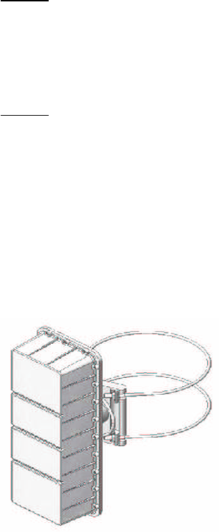
Pipe/Pole Mounting
With the pipe or pole mount option, the AP must be mounted vertically on a wooden or metal utility pole
up to 14.5” in diameter or a pipe with a diameter greater than 4". Ensure the unit is oriented so that the
text on the label is upright. This puts the internal antenna in the correct orientation, which is horizontal
polarization. Mounting the radio with a non-vertical orientation will prevent proper operation of the
system.
STEP 1 An adapter bracket is used to attach the AP to the pole clamp. Use a 1/2” wrench and the four
hex-head bolts with lock washers to attach the adapter bracket to the pole clamp. The bolts go through
the pole clamp holes, through the outside of the adapter bracket, and are secured on the inside of the
bracket with the lock washers and nuts. This assembly can then be attached to the AP base plate using
the two sets of four screws and lock washers. Ensure that the AP is oriented with the labels reading right-
side-up.
STEP 2 A cable is used to strap the radio mount to the pole or pipe. First loosen the two 4-bolt clamps
near the loop end of the cable so the cable can slide free through them. Wrap the two ends of the cable
around the pole or pipe and place the ends in the two notched sections of the mount. Then pull the loop
end of the cable to take up any slack and tighten the two 4-bolt clamps with a 1/2” wrench to secure the
cable. The nuts at the ends of the cable can then be tightened using a 5/8” wrench to cinch the cable
around the pole or pipe to the desired tension. If necessary, adjust the bracket rotation using the 5/8”
wrench on the two bolt heads.
Ensure all bolts are tight and the cable loop will not rattle against the unit in windy conditions. If the latter
is a problem, secure the loop of the cable to one of the ends of the cable with a cable-tie.
Figure 2.4B shows the AP with cables attached.
Figure 2.4B: AP Pipe or Pole Mounting

8
2.0 Installation
2.1 Unpacking the Unit
Carefully remove the equipment from its packing material and set it on a solid surface, such as a table
or desk. If it appears damaged in any way, notify the carrier and keep all packing materials for
inspection by the carrier’s agent.
2.2 Operating Environment
The AP is designed to operate in an outdoor environment at temperatures ranging from –40° to +60°C
(-40° to +140°F). As with all electrical equipment, operation outside specified temperature ranges will
accelerate the deterioration of components.
2.3 Power Requirements
The equipment has an auto-ranging internal power supply, which allows it to be powered from the 35-90
VAC 60 Hz power passing tap on the strand. This power passing tap must be capable of delivering a
minimum of 27 watts per AP. The AP will also work with a 48 VDC power source or 35-90 VAC 50 Hz.
Note: Most power passing taps are current limited and will shut off when the current gets above a certain
level. Care must be taken to ensure that under the worst case conditions of elevated temperature and
long lines between power supply and AP, that the AP can receive enough current without tripping the
overcurrent switch and shutting off the power. The AP also has an internal 2 amp slow-blow fuse.
2.4 Radio Mounting
Strand Mounting
There are two mounting brackets supplied. These are to be installed on the back of the AP using the
supplied screws and lock washers. With the brackets installed to the AP, secure the AP to the strand
using the two clamps provided. See figure 2.4A for details. A directional mounting bracket is also
available that allows the AP to be rotated 30° in either direction while on the strand.
Figure 2.4A: Strand Mounting
Note: If the strand mount option is selected, the radio must be mounted horizontally on the strand as
shown.

7
1.0 General Information
1.1 Overview
AirBridge™ is a wireless access solution designed to extend DOCSIS
®
or other services via strand or
pole mounted access points. The radio system consists of an access point (AP) and a subscriber unit
(SU). The AP mounts to the strand (CATV cable) and provides a point-to-point or point-to-multipoint radio
link in the 5.8 GHz UNII (Unlicensed National Information Infrastructure) band to several SUs located
about a mile away. The AP functionality includes powering from the strand, remote control and
monitoring via SNMP, and transmission and reception of standard DOCSIS
®
or other signals at the levels
found at a regular cable tap point. The SU will interface with a standard cable modem.
The AirBridge™ system provides a wireless entry point to the HFC (hybrid fiber/coax) network, extending
access to locations that may, due to cost or time constraints, be unable to connect to the system.
The
AP5800 includes an integrated DOCSIS 1.1 cable modem for communications and control. Note that
the data passing over the wireless network does NOT pass through the cable modem, so the cable
modem does not limit data rate or features available over the wireless link. In the downstream direction,
the AP5800 includes a repeater that demodulates the downstream data, removes noise and errors, and
remodulates. This ensures a top quality signal on the wireless link, independent of the quality of the
CATV signal.
1.2 Module Features
• Average 1-mile range
• Wide upstream gain range
• Excellent upstream noise figure performance
• Downstream output mutes if there is no valid input signal
• Reports power level of burst upstream signal
• Upstream can be set to auto mode, which minimizes noise put onto the cable system by keeping the
upstream output muted until there is a signal to transmit
• High reliability, state of the art design using microstrip MMIC (Monolithic Microwave Integrated Circuit)
and surface mount technology
• Conservative component derating and 100% burn in help ensure reliable operation
• Automatically tunes to downstream CATV frequency
• Internal modulator/demodulator regenerates signal for optimum downstream SNR
1.3 System Features
• Local control via RS232 command line interface
• Remote control via SNMP v1.1 (Simple Network Management Protocol)
• Flash memory for easy firmware upgrades
• Firmware upgradeable via TFTP (Trivial File Transfer Protocol)
• Internal power supply requires only 35-90 VAC power supplied on strand for operation
1.4 Options
The AP is available with the following options:
Mounting:
Strand This includes brackets and clamps to mount the radio in a horizontal orientation to the
cable strand. The internal antenna is mounted to produce a horizontal polarization by default.
Pole This option includes a mounting bracket and cable-based clamp to secure the radio to a
wooden or metal utility pole from 4” to 14.5” diameter, in a vertical orientation. The internal antenna is
mounted to produce a horizontal polarization by default.
Pipe This option is the same as the pole mount, except a shorter cable-based clamp is provided.
An internal antenna is provided in the radio. The antenna is oriented based on the type of mounting
selected. By default, the antenna is horizontally polarized, 60° horizontal beamwidth and 30° vertical
beamwidth. The antenna has a 14 dBi nominal gain, but with cable and radome loss, the effective gain is
12 dBi.
6
5.6 SNMP....….........................................................................................................................................26
APPENDIX A: Specifications...…………………………………………………………..…..……. 28
APPENDIX B: Setting Auto Mute Threshold……………………………………………………. 29
APPENDIX C: IP Addresses, Netmask, Etc…...…………………............................................30
APPENDIX D: Firmware Upgrades.....….................................................................................32

5
CONTENTS
1.0 GENERAL INFORMATION............................................................................….....................7
1.1 Overview.......................................................................................…................................................. 7
1.2 Module Features.................................................................…............................................................7
1.3 System Features................................................................................................................................7
1.4 Options...............................................................................................................................................7
2.0 INSTALLATION...................…...……................................................................….............….8
2.1 Unpacking the unit........................................................................................................................….8
2.2 Operating Environment.................. .............................................................................................….8
2.3 Power Requirements....................................................................................................................….8
2.4 Radio Mounting..............................................................................................................................…8
3.0 CONNECTORS & CONFIGURATION………………………………...…………………………10
3.1 AP Connection…………...................................................................................................................10
3.2 AP Configuration……...……............................................................................................................10
4.0 ACCESSING AP MENUS..……………………………………………………………………….12
4.1 Setting up……………………............................................................................................................12
4.2 Logon Menu.....................................................................................................................................13
4.3 Timeout.............................................................................................................................................14
4.4 The Main Menu.................................................................................................................................14
4.5 Using the Interface.…......................................................................................................................14
4.6 Submenus........................................................................................................................................14
5.0 REMOTE ACCESS...........…………......................................................................................25
5.1 Description.......................................................................................................................................25
5.2 Supported Network Protocols.…...................................................................................................25
5.3 Network Hardware Address.....…...................................................................................................25
5.4 Assigning an IP Address.…............................................................................................................25
5.5 Telnet.......…………………................................................................................................................26
4
INFORMATION TO USER
In accordance with FCC rules
“This device complies with Part 15 of the FCC Rules. Operation is subject to the following two conditions:
(1) This device may not cause harmful interference, and (2) This device must accept any interference
received, including interference that may cause undesired operation.”
“This equipment has been tested and found to comply with the limits for a Class A digital device, pursuant
to part 15 of the FCC Rules. These limits are designed to provide reasonable protection against harmful
interference when the equipment is operated in a commercial environment. This equipment generates,
uses, and can radiate radio frequency energy and, if not installed and used in accordance with the
instruction manual, may cause harmful interference to radio communications. Operation of this equipment
in a residential area is likely to cause harmful interference in which case the user will be required to
correct the interference at his own expense.”
CAUTION: Any changes or modifications not expressly approved by CommScope could void the user’s
authority to operate the equipment.
WARNING:
In order to comply with the FCC radio frequency exposure limits of Part 1.1310, this equipment must be
installed in such a way as to provide a minimum separation distance of 2 ft. from the transmitting antenna
to persons nearby.

3
SAFETY PRECAUTIONS
1. Before installing and operating this equipment, read all Safety, Installation and Operating sections.
Retain this manual for future reference.
2. Follow all instructions — Failure to do so may result in damage to the unit or severe personal injury.
3. The user should not attempt servicing. There are no user serviceable parts inside. Refer all servicing
to factory-qualified personnel.
4. Cleaning — Do not use liquid or aerosol cleaners. Use a damp cloth for cleaning.
WARNING!
Do not work on the system or connect or disconnect cables during periods of
lightning activity.
2
AirBridge™ Access Point Manual; Manual AirBridge™ AP (October 2005)
© 2005 CommScope, Inc. of North Carolina. All rights reserved.
No part of this publication may by reproduced in any form or by any means or used to make any
derivative work (such as translation, transformation or adaptation) without written permission from
CommScope.
CommScope reserves the right to revise this publication and to make changes in content from time to
time without obligation on the part of CommScope to provide notification of such revision or change.
CommScope provides this guide “as is,” and without representation or warranty of any kind. CommScope
disclaims all warranties, express or implied, with respect to the documentation and information set forth
herein including, but not limited to, any warranties as to its non-infringement of third party rights,
merchantability and / or fitness for a particular purpose. In no event will CommScope be liable for any
damages (including consequential, incidental or special damages) or for any claim by any third party
resulting from the publication, distribution or use of the information contained herein. CommScope may
make improvements to or changes in the product(s) described in this manual at any time.
Information and specifications included in this publication are subject to change without notice.
Printed in Canada.

Broadband Wireless Access Point
AP5800
INSTALLATION AND OPERATION MANUAL