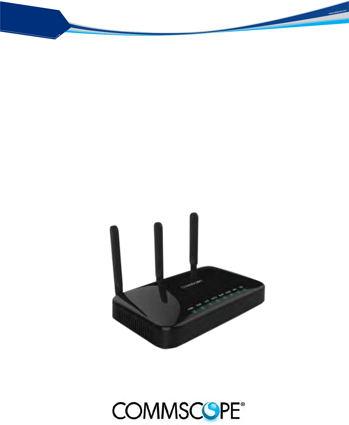
CommScope of North Carolina C1004W 10G GEPON ONU User Manual C604GR
CommScope, Inc. of North Carolina 10G GEPON ONU C604GR
User Manual
solution
PON
C1004W - 10G EPON ONU
Installation and Professional’s Guide
Version 1.4
* This manual should be provided to professional installers educated and
trained with product installation method and product composition method.

solution
PON
C1004W Installation Guide
III
Table of Contents
Table of Contents ........................................................................................................... III
Safety Precautions ......................................................................................................... 1
Product Introduction ....................................................................................................... 3
Features ............................................................................................................................ 3
Appearance ...................................................................................................................... 4
Ports ................................................................................................................................. 5
LEDs ................................................................................................................................. 6
Contents of the Package ................................................................................................... 7
Installation ....................................................................................................................... 8
LED Indicator .................................................................................................................. 10
Web GUI configuration setting ...................................................................................... 11
Default configuration setting ........................................................................................... 11
Web Login ....................................................................................................................... 11
VLAN assignment ........................................................................................................... 12
Device Info .................................................................................................................... 15
Advanced Setup / WAN Service ................................................................................... 17
Advanced Setup / Interface Grouping .......................................................................... 22
Wireless / Basic ............................................................................................................ 24
Wireless / Security ........................................................................................................ 25
Wireless / Advanced ..................................................................................................... 27
Troubleshooting ............................................................................................................ 28
Specification ................................................................................................................. 30
solution
PON
C1004W Installation Guide
1
Safety Precautions
Warning
Before you install the C1004W unit, read this section. Product installation should be
conducted only by professional installer who has been accurately trained.
Electrical safety
Always use caution whenever handling live electrical material and
contacts.
Do not install electrical equipment in wet or damp conditions.
Ensure that the power source for the unit is adequately rated to assure
safe operation and provides current overload protection.
Do not allow anything to be put on the power cable, and do not place
this unit where people will stand or walk on the power cable.
This unit should be used with the approved power adaptor which is
included in the product package.
Warning
Do not open the enclosure without Commscope’s permission and technical support, which
voids the warranty.
Laser safety
Use of controls or adjustments, or performance of procedures other
than those specified herein may result in hazardous laser radiation
exposure.
To avoid exposure to radiation, do not stare into the aperture of a fiber-
optic port. Invisible radiation might be emitted from the aperture of the
port when no fiber cable is connected.
Do not bend the optic fiber cables severely, which may damage the
fiber or prevent the signal from being transmitted properly.
Always keep unused fiber-optic ports capped with a clean dust cap.
Warning
Invisible laser radiation may be emitted from disconnected fibers or connectors. Never stare
into beams or look directly to optical connectors.
Preventing EMI
When you run wires for any significant distance in an electromagnetic
field, electro magnetic interference (EMI) can occur between the field
and the signals on the wires.
Bad plant wiring can result in radio frequency interference (RFI).
If Strong EMI occurs in the installation place, consult RFI experts to get
rid of it.
solution
PON
2
Accessibility Safeguards
Warning Never use “Administrator” nor “Operator” login account except professional installer!
Warning
Supplier will not be liable for any damage or misoperation caused from incautious
configuration attempted by end user who tries with “Administrator” or “Operator” login
account.
Grade on accessibility
Three login accounts are available as per their own authority and
capability.
“Administrator” account gives the top most authority and “User”
account gives the least.
The account information is presented in this manual but this does not
mean any end user may dare to configure the unit.
This product must be installed and configured by professional installer
only.
Should there be any mis-configuration made upon the device (e.g. RF
band selection or country selection) by end user the device would not
operate properly.”

solution
PON
C1004W Installation Guide
3
Product Introduction
C1004W is a single family unit type ONU which has a 10G EPON uplink and 4 Gigabit Ethernet
ports for service as well as dual band WiFi interfaces. Each service port can support upto 1 Gbps
bandwidth meanwhile WiFi interface supports IEEE 802.11 b/g/n/ac. Besides, OAM functions like
remote detection/configuration via ACS, web configuration and QoS control features are also
obtainable for smoother operation and maintenance.
Features
Various speed combination supported
Diverse Downstream/Upstream speed sets for the uplink segment are available
- 10Gbps / 10Gbps
- 10Gbps / 1Gbps
- 2Gbps / 1Gbps (Turbo mode) - planned
- 1Gbps / 1Gbps - planned
Uplink segment means the portion between OLT and ONU.
[Note] 2Gbps / 1Gbps (Turbo mode) and 1Gbps / 1Gbps are only available provided that
appropriate optic module is equipped at the corresponding OLT port.
Compliant to cablelab’s DPoE specification
Right for the MSOs who want to migrate to EPON technology
Management via efficient OAM
Remote detection and configuration by way of TR-069 (planned)
EPON OAM
Authentication
Charging
Dualband wireless access in concurrent manner
IEEE 802.11 ac as well as b/g/n are supported.
- At 2.4 GHz: IEEE 802.11 b/g/n
- At 5 GHz: IEEE 802.11 ac
Local Configuration via web GUI
For monitoring and settings
solution
PON
4
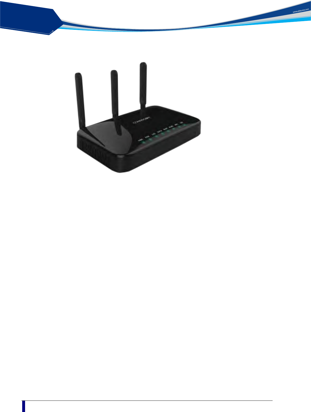
Appearance
Figure 1 Front view of C1004W
Designed to be installed either wall mount or the desk placement.
Physical dimension & weight
- 288.50(W) x 186.6(D) x 150.00(H) mm
- 820g
Power adapter
- Input: 100 ~ 200VAC, 50 ~ 60 Hz
- Output: 12VDC, 3A
solution
PON
C1004W Installation Guide
5
Ports
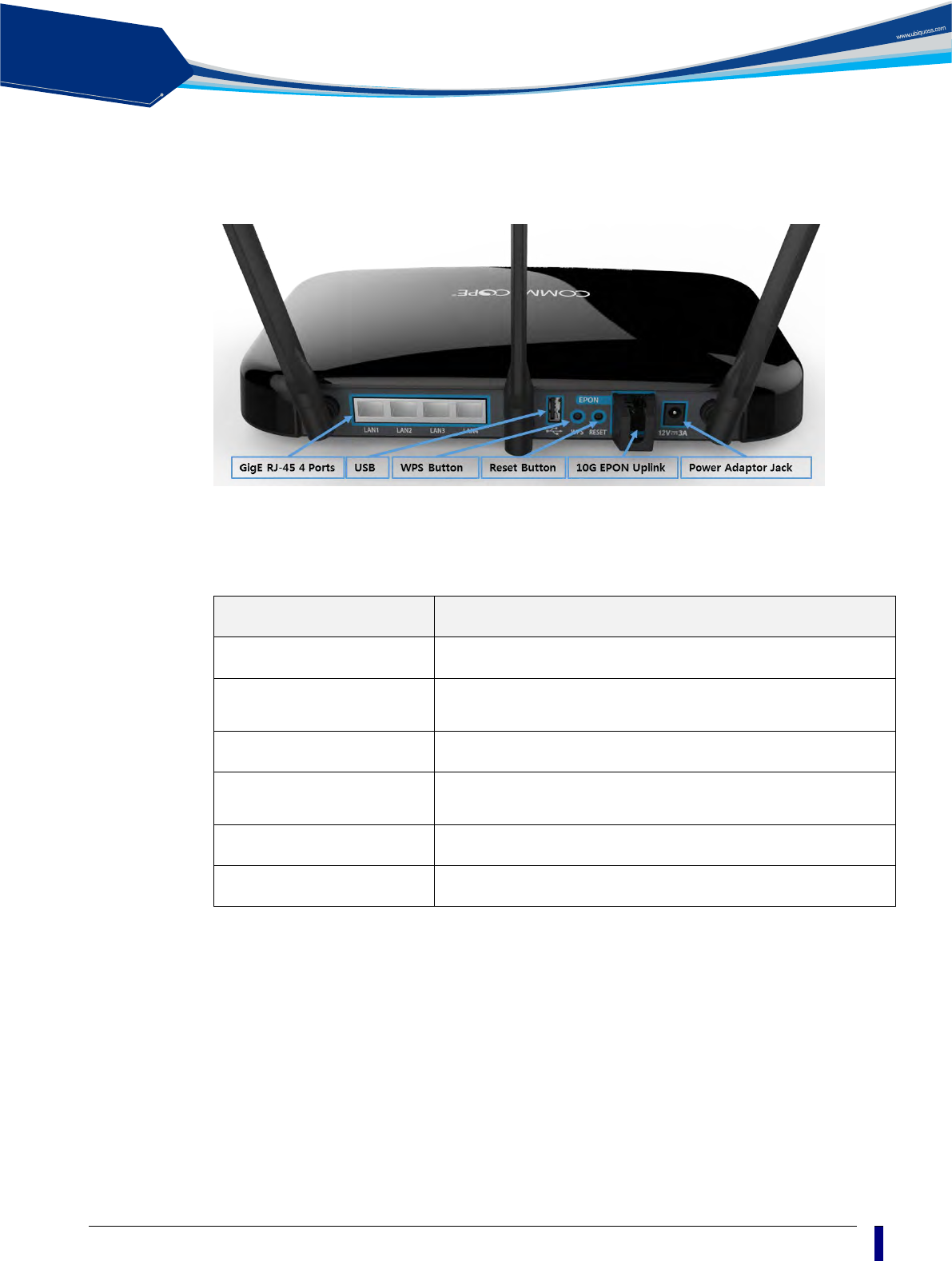
Figure 2 Rear view of C1004W
Table 1 Descriptions of the ports on the rear panel of the C1004W
Port and Button Function
Four Gigabit Ethernet ports Four 10/100/1000Base-TX ports used for service connection
USB port
Updated system image is downloaded via this.
(To be operational in MP version)
WPS button Activate Wi-Fi Protected Setting
Reset button
Press for 1~3 seconds to reset the unit.
Press for more than 15 sec to get back to factory default setting.
10G EPON Uplink 10G EPON ports (SFP+ type) used for uplink connection
Power adapter jack Hole for the power inlet from PA.
solution
PON
6
LEDs
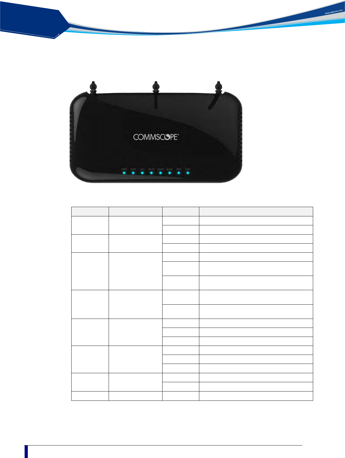
Figure 3 Top view of C1004W
Table 2 Descriptions of the LEDs on the front panel of the C1004W
Silk Screen
Name
Status
Indication
PWR Power supply LED
Green On
Power is fed.
OFF
No power is fed.
PON Authentication LED
Green On
10G Link On
OFF
Link Off
LOS Loss of Signal
Purple On
Optic transceiver is NOT equipped.
Red On
PON Link is NOT established properly.
Or, continuous optic signal is detected.
OFF
PON Link is established properly. I.e. in
normal status.
DATA Data port LED
Blue Blink
Packets are being transmitted between OLT
and ONU.
OFF
No packets are being transmitted between
OLT and ONU.
WLAN1 WLAN1 port LED
Blue On
5G Wi-Fi is in Active status.
Blue Blink
5G WPS is in operation.
OFF
5G Wi-Fi is in Inactive status
WLAN2 WLAN2 port LED
Blue On
2.4G Wi-Fi is in Active status.
Blue Blink
2.4G WPS is in operation.
OFF
2.4G Wi-Fi is in Inactive status.
WPS WPS port LED
Blue Blink
WPS is in operation
Off
WPS is NOT in operation
USB
USB port LED
Blue On
USB device is attached
solution
PON
C1004W Installation Guide
7
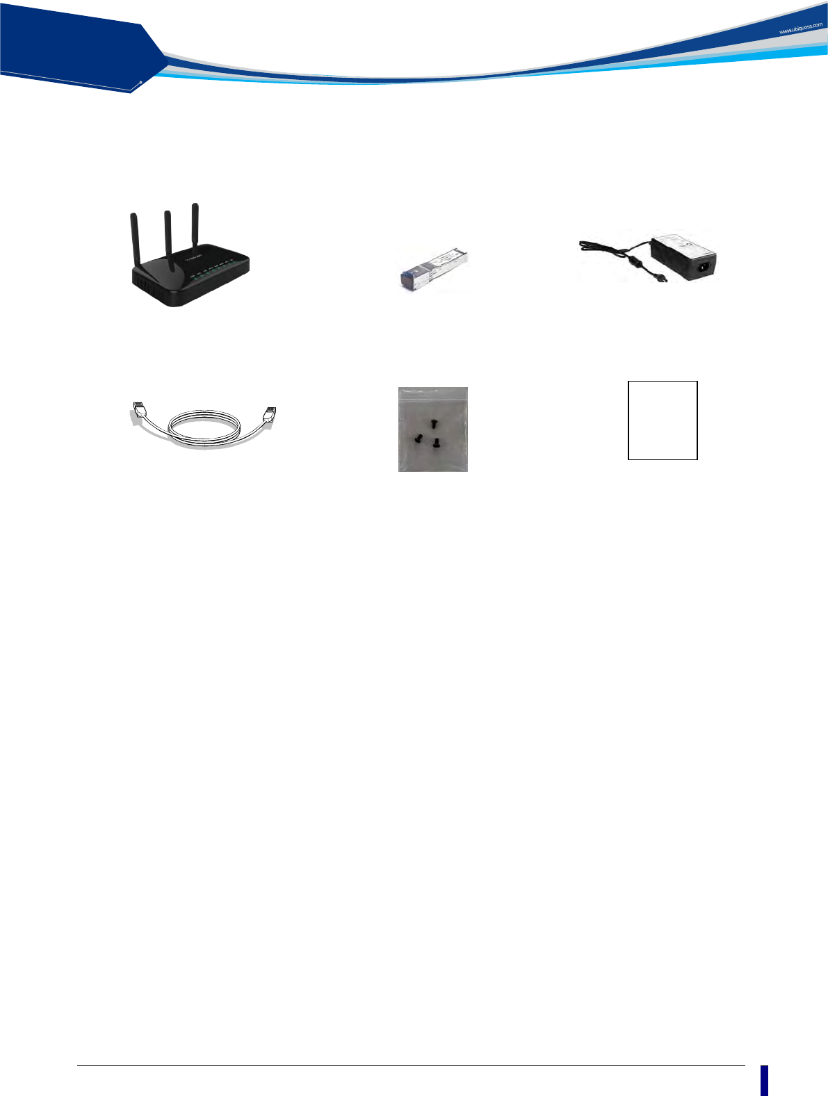
Contents of the Package
C1004W
Ethernet Cable
Installation
Guide
Transceiver module
Power Adapter
Star-shaped screws
Quick Install Guide
solution
PON
8
Installation
Warning
Invisible laser radiation may be emitted from disconnected fibers or connectors. Do not stare into
beams or view directly with optical instruments.
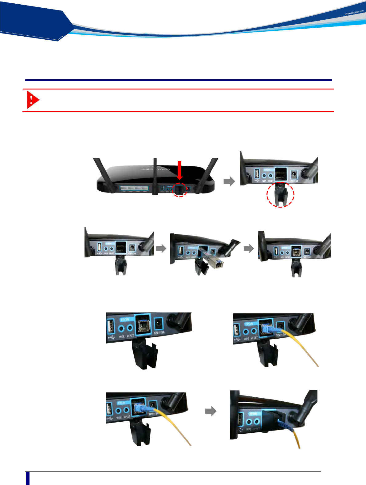
The sequence of installation is described from step 1 to 9 as below:
Step 1: Push gently down the hinged cover to connect the 10G SFP+ optic module.
Step 2: Slide the 10G SFP+ optic module into the socket on the ONU.
Step 3: Connect the SC/APC connector on one end of a single-mode optical fiber into the
optical terminal of the optical outlet (it could be a splitter or PIM card of an OLT) and
the other end into the PON port of C1004W by pushing it until a click sound is heard.
Step 4: Lift the hinged cover back into its position with care.
solution
PON
C1004W Installation Guide
9
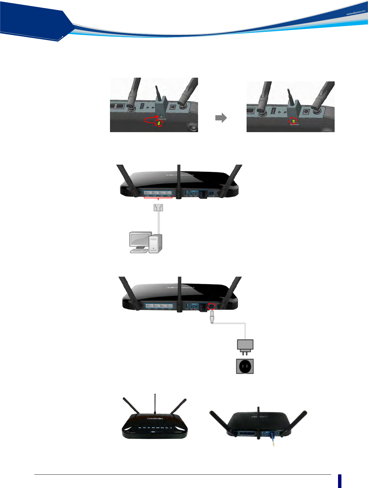
Step 5: Fix the hinged cover by fastening the enclosed screw at the screw hole at the bottom
using 6-lobe star wrench (a special tool which is not enclosed).
Step 6: Connect any LAN port of C1004W and a PC with an Ethernet cable which has RJ-45
plug head. Up to 4 PCs or its equivalent (e.g. IP phone) can be accommodated.
Step 7: Connect the rated power adaptor (12VDC 3A) to the power jack in the unit.
Step 8: Raise the antennas positioning for the best WiFi performance.
Step 9: Now you are ready to use.
solution
PON
10
LED Indicator
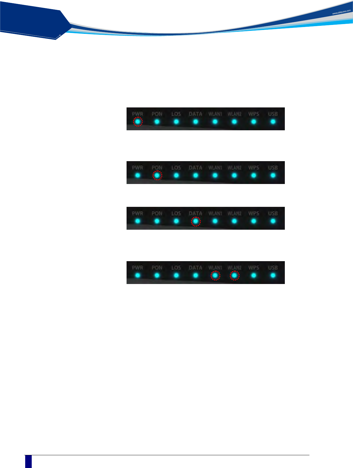
The following steps can be referenced to see if the unit is in normal status when all the necessary
connection for the unit is completed.
Make sure that the POWER LED is ON.
Make sure that the PON LED is ON in several seconds or minutes. If
PON LED is red, the optical signal is very low, so please contact your
service provider.
If everything is installed properly, the user can see the DATA LED blink
while Internet data is being sent or received.
If you set the wireless configuration properly, the user can see the
applicable wireless device WLAN LED blink while data is sent or
received.
solution
PON
C1004W Installation Guide
11
Web GUI configuration setting
Default configuration setting
When the installation of C1004W hardware is finished it is operable to get on internet access
via wireline and wireless ports.
The uplink interface of 10G EPON is configured to operate as NAT mode as its default.
Therefore once the uplink interface is properly connected all the LAN ports and wireless
interface work out. In this case each LAN port will be assigned private address for the
internal routing within C1004W.
If any changed mode of operation is required other than default configuration, web GUI
configuration work will be needed. The actual modification will vary according to operator’s
requirement or service policy. An example of most frequently used configuration setting
regarding VLAN assignment is presented later in this section.
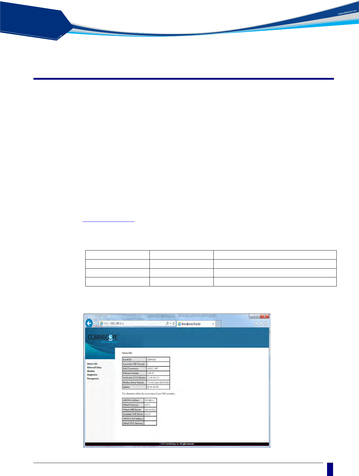
Web Login In order to configure C1004W via Web GUI page, connect your PC to any port of C1004W
service ports with the enclosed RJ-45/UTP cable. After connecting PC on a LAN port, type
http://192.168.1.1 in the URL window of your Web Browser.
C1004W provides 3 accounts as follows:
Account
Id / password
Usage
Administrator Login
admin / admin
For both changing and viewing the setting
Operator Login
support/support
Used when accessing the unit remotely
User Login
user / user
For viewing only
When you connect the unit via Web Browser, the following screen will show up as its starting
page.
solution
PON
12
Note
If it does not work, after pushing RESET button at the rear of system,
then wait one or two minutes and try it again.
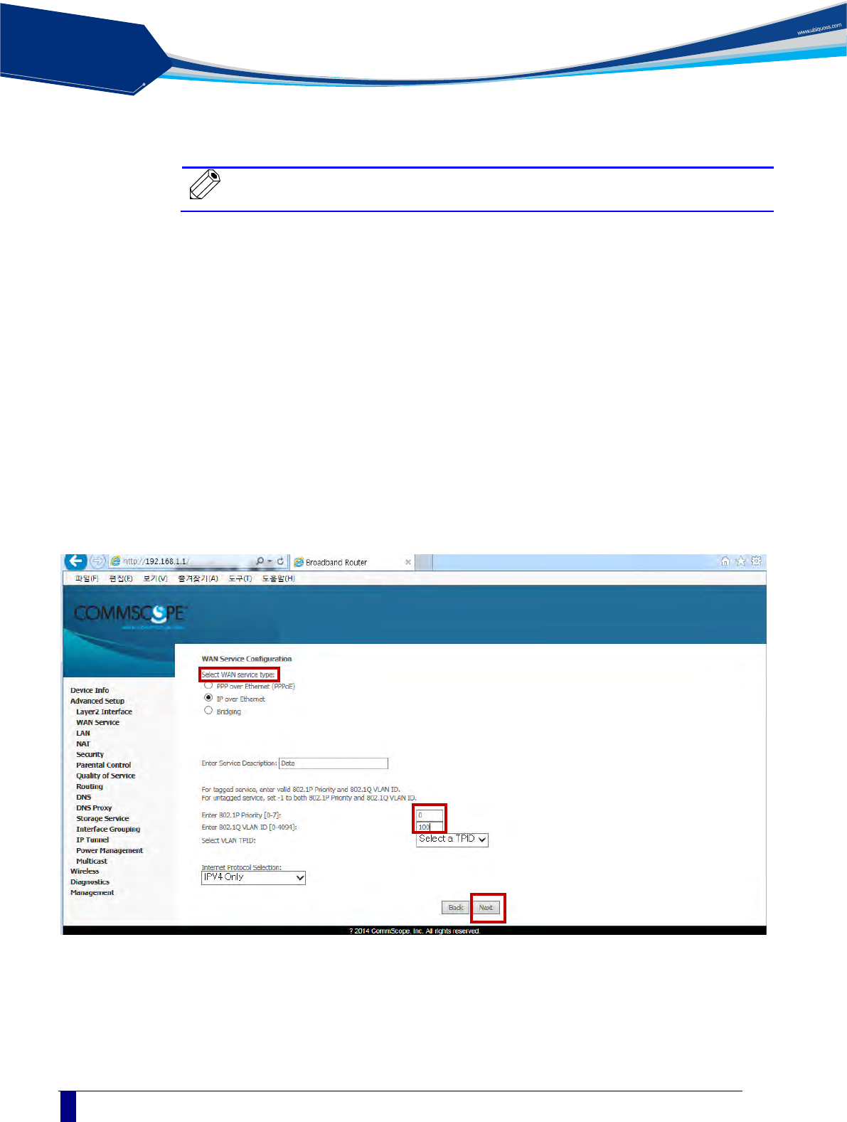
VLAN assignment
Go to the menu item in the left side of starting window.
- Select ‘Advance setup’ -> ‘Wan Service’
- Configure interface and Vlan setup
- With respect to ‘WAN Service Configuration’
IP over Ethernet is for NAT mode
Bridging is for Bridge mode
- Assign the COS value and VLAN ID to be used
solution
PON
C1004W Installation Guide
13
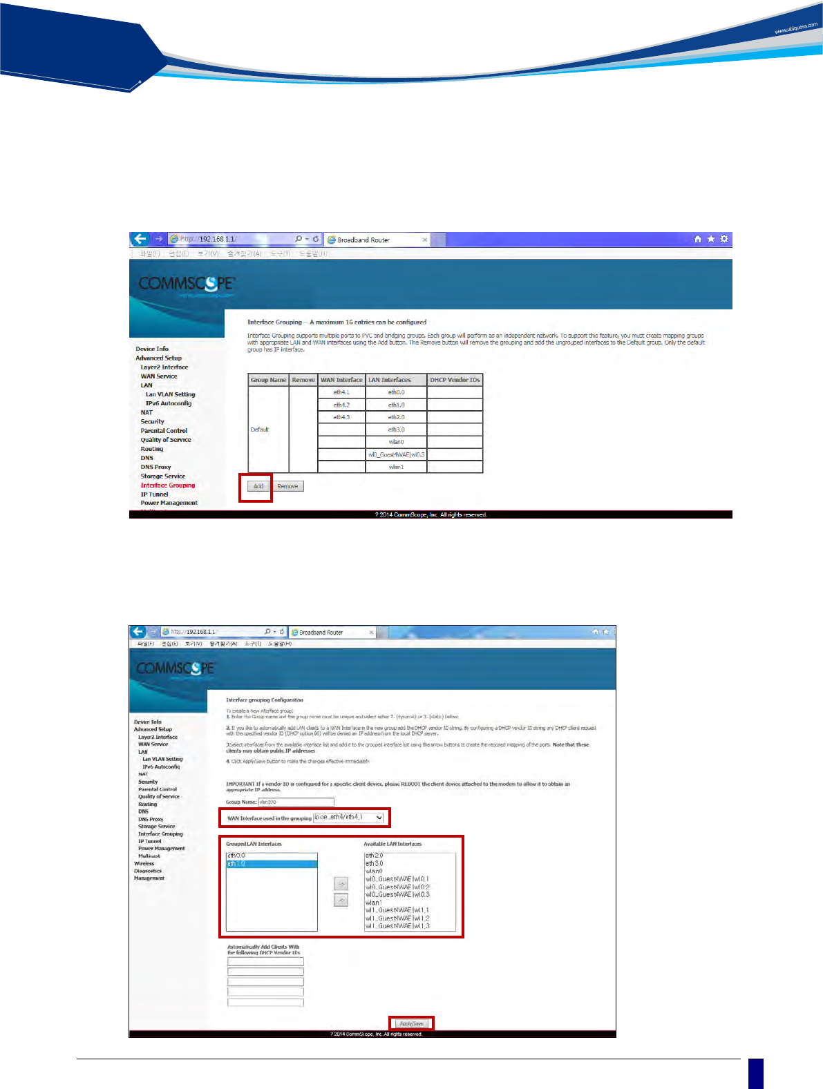
- Select ‘Advance setup’ -> ‘Interface Grouping’
- Click ‘Add’ button.
- Select an entry among ‘WAN Inteface used in the grouping’ menu.
- Move as many interfaces as wish from the right box to left. Then the moved interface will be
assigned to the newly created VLAN Id.
solution
PON
14
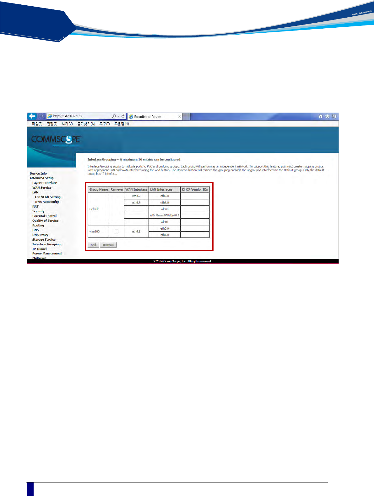
In the example two physical interfaces of port 1 and port 2 are moved to ‘Group LAN Interface’.
- Check out to see if VLAN 100 is associated with port 1 and port 2 in the table shown below. (you may
again select ‘Advance setup’ -> ‘Interface Grouping’)
solution
PON
C1004W Installation Guide
15
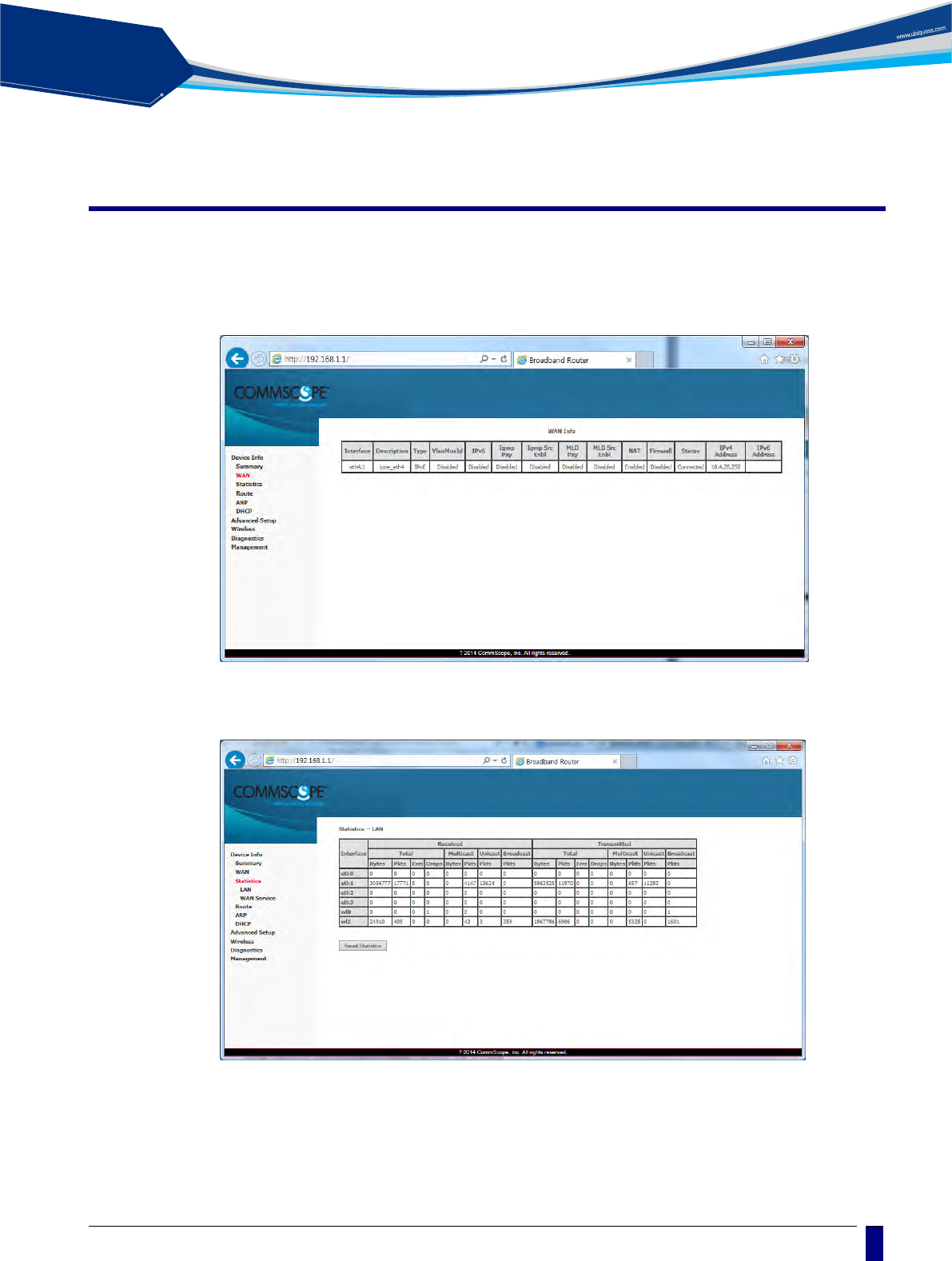
Device Info
Device Info shows the basic information about ONU. The information to be able to search is
as follows:
WAN status and IP Information
Statistics information about WAN / LAN / WLAN
solution
PON
16
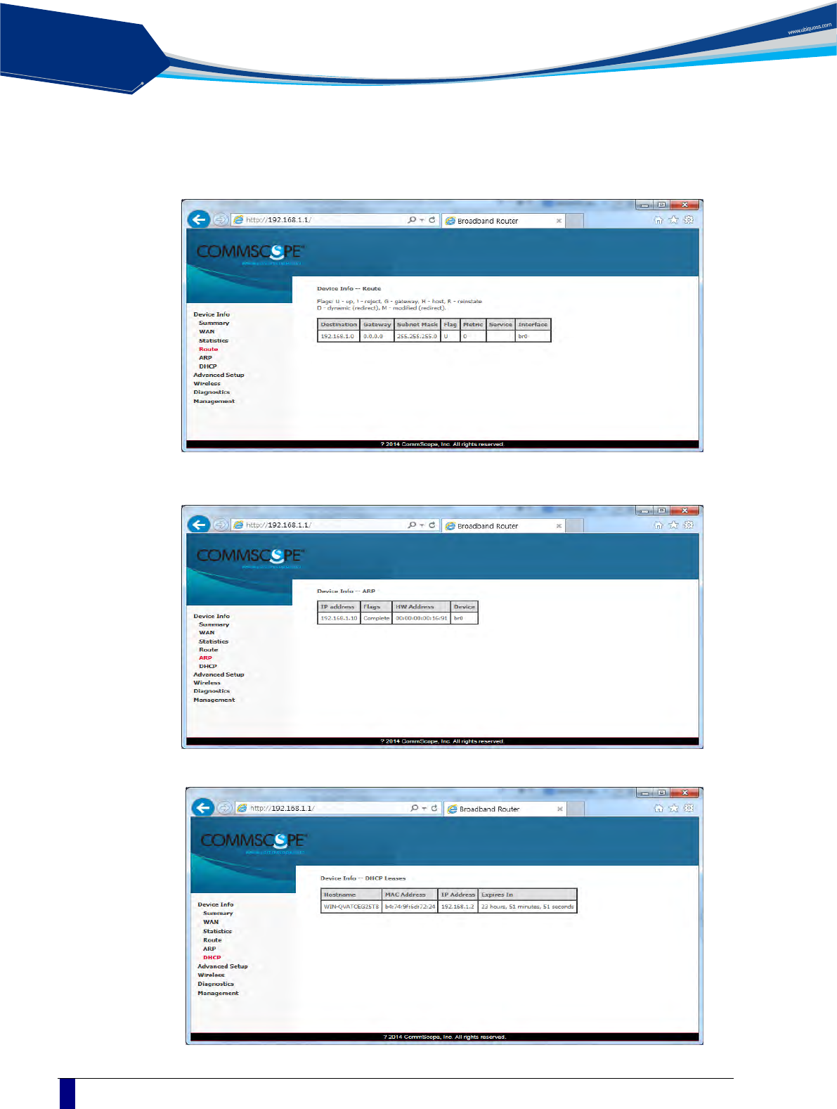
Route Information
ARP Information
DHCP Information assigned with LAN / WLAN
solution
PON
C1004W Installation Guide
17
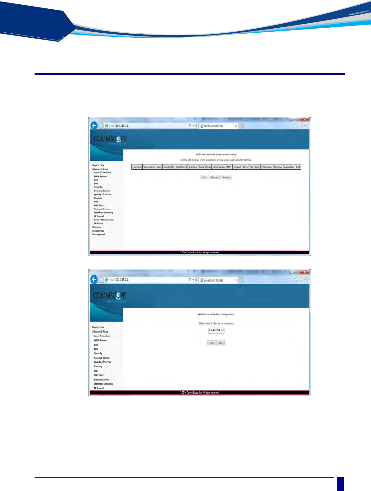
Advanced Setup / WAN Service
You can create the Interface for various WAN service based on the assigned WAN Physical
Port.
To create WAN Service Interface, click [Add] button on [WAN Service Setup Display].
solution
PON
18
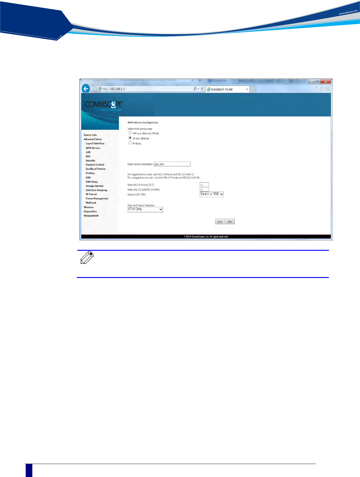
If you click [Next] button, you can assign VLAN ID about 802.1Q and a priority about WAN
service type and 802.1P.
Note
In case of assigning as Untagged Service from WAN Service Interface,
you must set it as ‘-1’.
solution
PON
C1004W Installation Guide
19
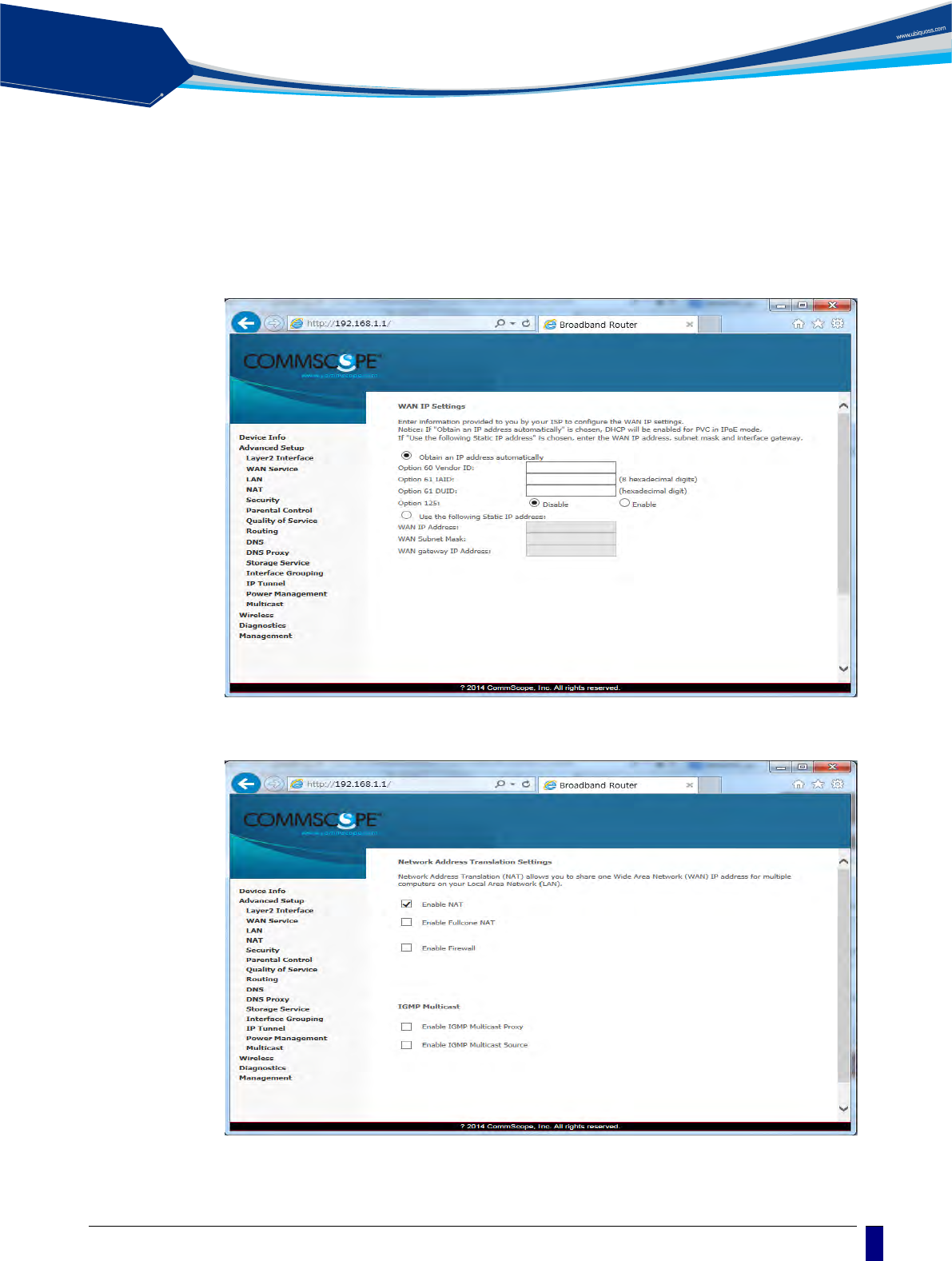
If you click [Next] button, you can set IP about WAN Service Interface. When the system
needs to obtain an IP address automatically from DHCP server connected with WAN
network, select [Obtain an IP address automatically] radio button.
When the system uses the static IP address on WAN Service Interface, select [Use the
following Static IP address]. Then set Static IP Address, Subnet Mask and Gateway IP
Address.
If you click [Next] button, you can enable NAT and Multicast function on the WAN service
Interface.
solution
PON
20
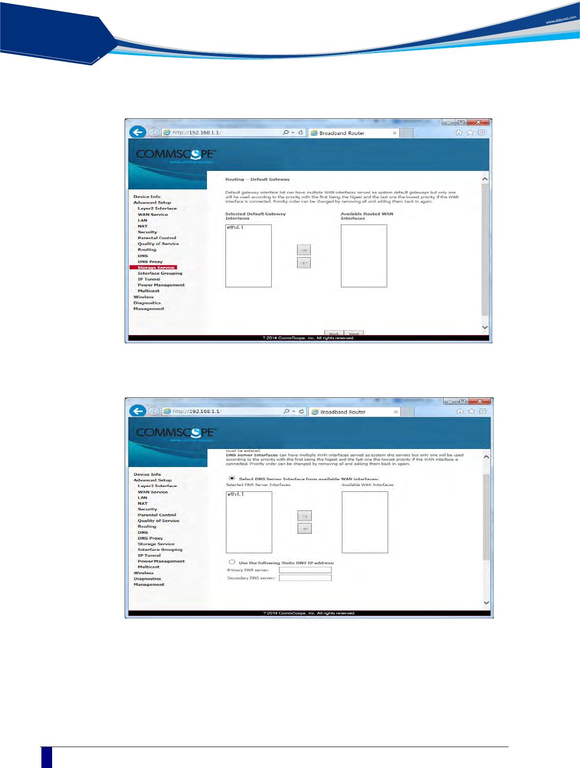
If you click [Next] button, you can assign Default Gateway about WAN Service Interface.
If you click [Next] button, you can set DNS Server about WAN Service Interface.
solution
PON
C1004W Installation Guide
21
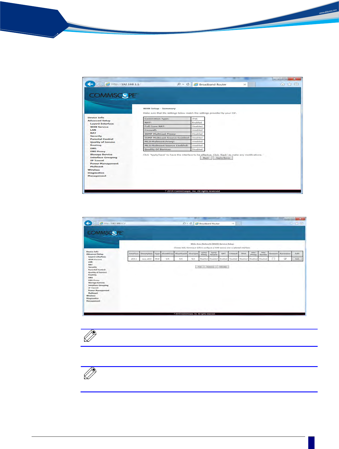
When the above procedure is done, it shows the information about WAN Service to be
applied finally.
When you click [Apply/Save] button, the information of the set WAN Service Interface is
listed and it is done about WAN Service Interface.
Note
If you change 802.1P, 802.1Q on the created WAN Service Interface,
you must register again after deleting WAN Service.
Note
In case that you assign 802.1Q VLAN-ID individually on the several
WAN Service and do grouping LAN Interfaces, refer to Interface
Grouping setting on Advanced Setup Section.
solution
PON
22
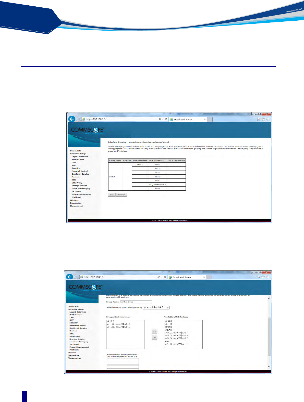
Advanced Setup / Interface Grouping
By creating several groups, you can manage several LAN Interfaces with Interface grouping
provided from Advanced setup.
By default, one default group includes all LAN Interfaces.
To create Interface Group, click [Add] button on [Interface Group Display]
Set Group Name with easy name to acknowledge. To set WAN Interface for using to create
Group, select list box. After selecting WAN Interface, select LAN Interface for including to
group to create.
Select LAN Interface to move on the [Available LAN Interfaces] BOX.
If you click arrow button, it moves to the [Grouped LAN Interfaces] BOX.
solution
PON
C1004W Installation Guide
23
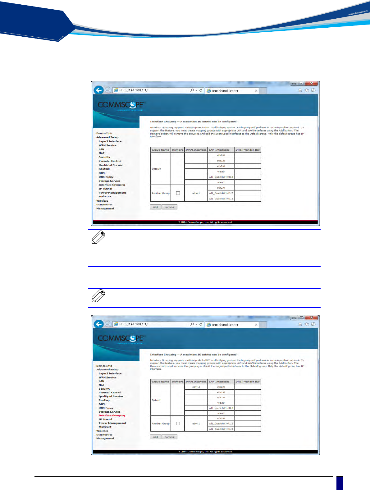
After the creating Group by clicking [Apply/Save] button, the Group is created like following
screen.
Note
To process incoming traffic after applying VLAN ID per each
Group, one WAN interface per Group system is applied. Thus,
to set like the following screen, you must add WAN interface
before creating Group.
Note
To know the way of adding WAN Interface, refer to [Advanced
Setup / WAN Service].
solution
PON
24
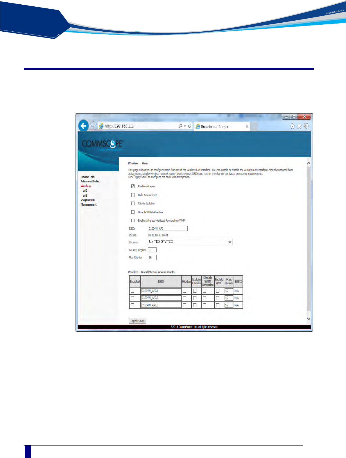
Wireless / Basic
You can set the basic Wireless configuration. It provides 4 Wireless interfaces and you can
set each WLAN activation and Scanning activation from network list. It is possible to set
SSID and a nation for wireless channel.
solution
PON
C1004W Installation Guide
25
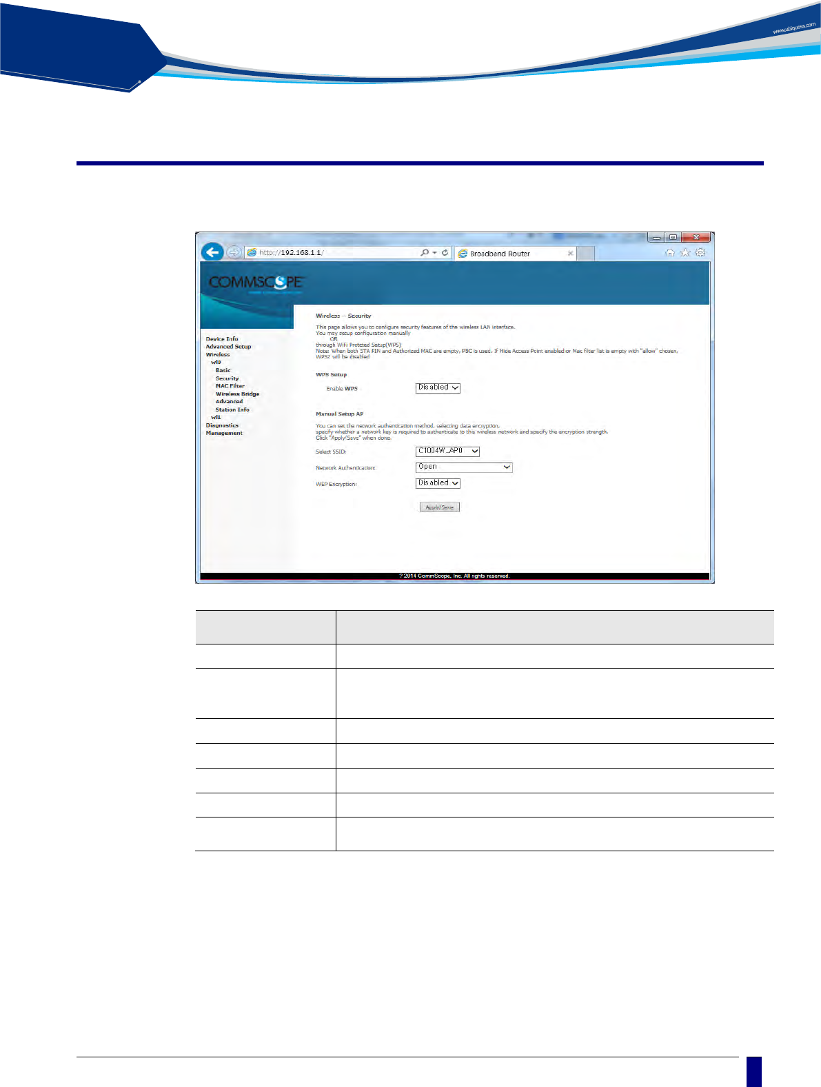
Wireless / Security
You can set the security of wiress. It is possible to apply the specific network authentication
per each SSID. It is also possible to set the key encryption for authentication or not.
Network authentication Way
Authentication
way
Description
Open No Encryption.
Shared
WEP
64Bit : 5 or 10 numbers security key
128Bit : 13 or 26 security key
802.1X Uses Radius Server / WEP key
WPA2 Advanced WPA
WPA2-PSK WPA / WAPI passphrase Key
Mixed WPA2 /WPA Mixed WPA and WPA2
Mixed WPA2 / WPA-
PSK
Mixed WPA-PSK and WPA2-PSK
solution
PON
26
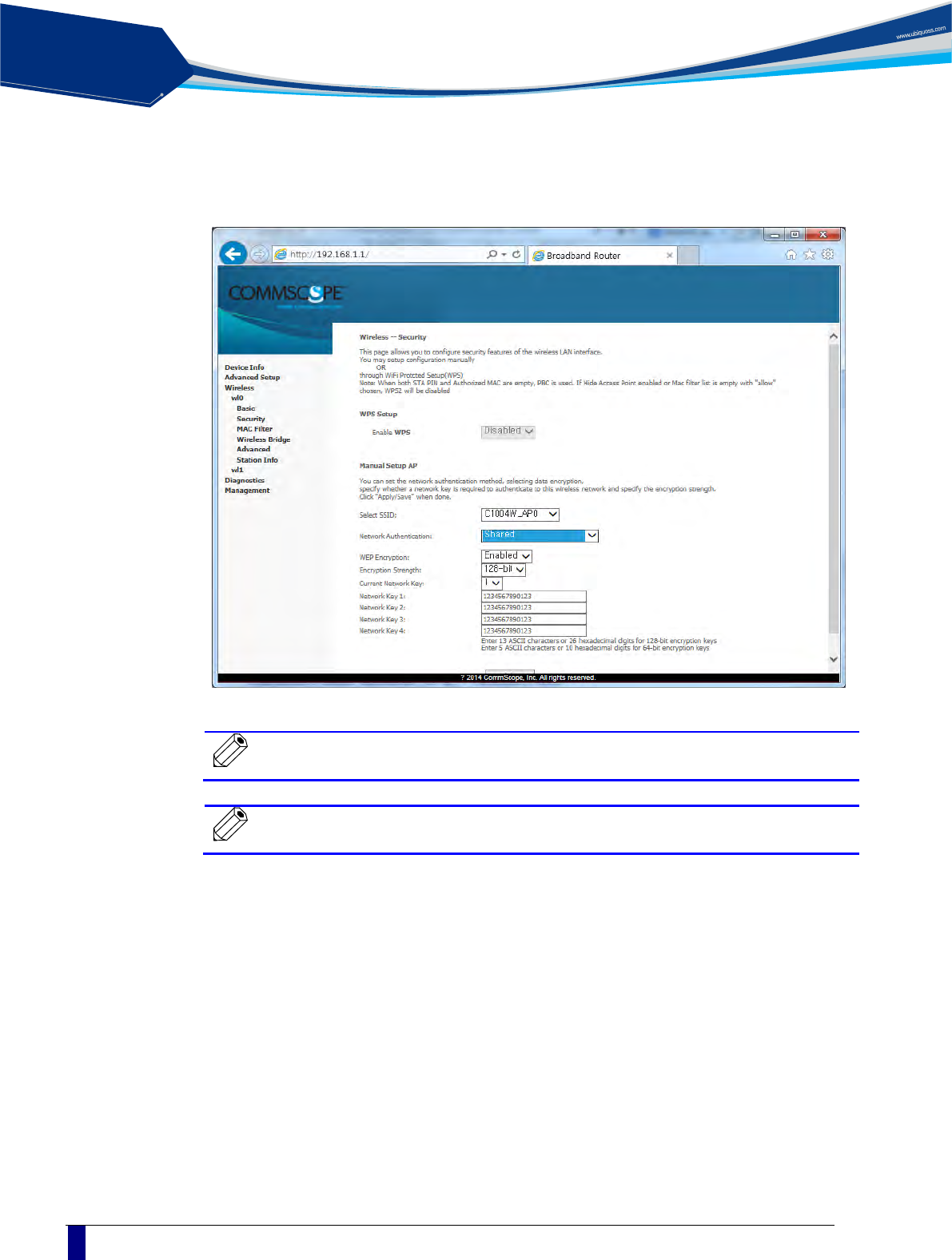
To apply “Shared” that is the most basic Network Authentication way, Select “Shared” on the
Authentication Select Box.
Note
When you select each Network Authentication way, the screen shows
the different setting options.
Note
You can select Current Network Key among 1~4. We recommend
changing a new Network key value instead of default value.
solution
PON
C1004W Installation Guide
27
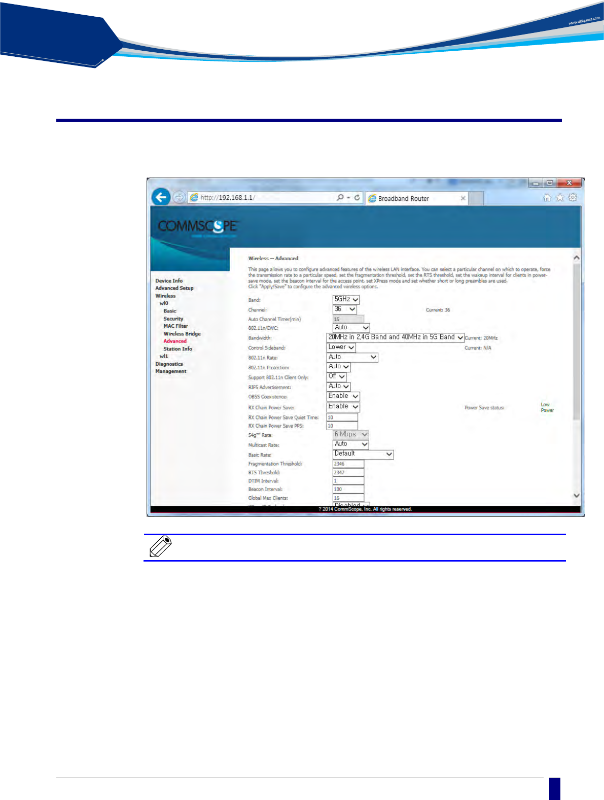
Wireless / Advanced
It is possible to set the advanced setting about Wireless LAN Interface. You can set the
specific channel to want to run. You can set the transmission speed according to bandwidth
and Beacon interval f or A P.
Note
You can use 2.4GHZ Band in wl1, 5GHZ Band in wl0.

solution
PON
28
Troubleshooting
Possible troubles and its quick remedy:
Symptom 1: “Can not access to the Internet” -
Step 1 Make sure that the ONU is turned on. Once you turn on the power, the
POWER LED on the front panel of C1004W should be lit. If the POWER
LED is not lit, please check if the power cable is connected to the power
inlet of ONU properly. If the problem persists, please call Service
Provider.
Step 2 Make sure that the optical line is connected properly. Once the optic
fiber is connected, the PON LED on the front panel of C1004W should
be lit on within few seconds. If the PON LED blinks, call Service
Provider to check the optical line connection.
Step 3 Make sure that the LAN cable is connected properly. Once the LAN
cable is connected and user PC is turned on, LAN LED should be lit on.
If the LED is not lit, check the cable connection.
Step 4 Make sure that network setting of your PC is correct. Select “set to
‘Obtain IP address automatically’.
Symptom 2: “All the cables are connected, but still can not obtain IP address”
Step 1 Look for the Network Neighborhood or My Network Places icon in your
PC. If it is not there, try your Start Menu.
Step 2 Right-click the Network Neighborhood/My Network Places icon. A drop-
down menu will appear.
Step 3 Choose the "Properties" option, which is generally found at the bottom
of the menu.
Step 4 Look for an icon named "Local Area Connection". The icon looks like a
pair of computer connected by a link. Double-click this icon.
Step 5 Click the "General" tab, if it is not already selected. You will see a list of
protocols to choose.
Step 6 Scroll down and choose Internet Protocol (TCP/IP), and then click the
button that is labeled "Properties".
Step 7 Again, click the "General" tab, it is not already selected. You will see
two choices:
1) "Obtain an IP address Automatically"
2) "Use the following IP address..."
Step 8 Choose option “1)”
Step 9 Click OK

solution
PON
C1004W Installation Guide
29
Symptom 3: “WiFi access to the unit is not available”
Step 1 Make sure DPoE provisioning has been finished normally by checking
out PON LED.
Step 2 Power cycle the unit to reboot.
Symptom 4: “DPoE Provisioning for the unit is not finished properly, i.e. the PON LED on
C1004W does not light up or blink”
Step 1 Connect to the console port or management port of the associated OLT.
Step 2 Execute the following CLIs to diagnosis the status of the C1004W.
CLI
Target action
show cable modem
To see if the unit is on-line
show cable modem
mac_address vervose
To retrieve the DDMI information which proves its
integrity
show cable modem cpe
To check out CPE information (e.g. IP address,
MAC address)
show epon onu
To see if the unit is on-line
show 10gpon olt ddmi
slot/port mac_address
To check out the strength of the RX signal from
C1004W
show slot
To check out the active status of PIM slot
show epon olt
To get the MAC address of 10G PIM card
show cable firmware
To get the cable firmware information (Xenu)
show logging cable
To see the DML log to find the reason why
provisioning hasn’t worked out right
show bundle
To see the DHCP server configuration whether it
works out properly
tcpdump interface
vlan4001
To look into the packets that flows through the
default bundle
Step 3 If the diagnosis result of step 2 says that C1004W has got any fault at
its uplink interface(i.e. Xenu), then reboot the uplink interface part of the
unit.
Use the CLI of ‘clear cable modem all reset’ to reboot the unit.

solution
PON
30
Specification
Item
Description
Standard
IEEE 802.1q
System Architecture
Type
Desktop
Size (mm)
288.50(W) x 186.60 (D) x 150.00(H) (incl. antenna)
Weight
820g
Power
Input: 100 ~ 220VAC, 50~60Hz
Output: 12VDC, 3A (The input terminal that a power adaptor is connected to)
Consumption: Max 34W
Available Interface
PON interface
10/10, 10/1, 2/1, 1/1 Gbps supported
User interface
Four 10/100/1000base-Tx, MDI/MDIX Auto-Negotiation
Wi-Fi Interface
802.11b/g/n/ac compliant
Environmental
Condition
Operating Temperature/humidity: 0℃ ~ 50℃
Storage Temperature/humidity: -20
℃
~ 60
℃
In compliance with EMI/EMC Class
Function and
Performance
EPON
IEEE802.3ah MPCP, OAM compliant
802.1Q VLAN
Per LLID Filtering/Classification
Supports up to four Logical Link IDs (LLID)
AES-128 Downstream decryption
Dying Gasp
Automatic Plug and Play function for WAN PON Port (Discovery and
Authorization)
L2 Features
IEEE802.1Q VLAN(Tagged, untagged by Port) for WAN Port
Maxumum 16 active VLAN
VLAN ID range of 1~4094
Support up to 64 MAC Address
L3 Features
DHCP Client/Server
In NAT mode, IP will be assigned from the IP Pool of the device, and in
Bridge mode, the IP will be assigned from the DHCP server in the
network
Support DNS/DNS Proxy
Multicasting
IGMP v1/v2/v3
IGMP proxy/snooping for IPTV service
IGMP Immediate Leave on/off
32 Multicast Group entry
Multicast throughput 1Gbps
NAT/NAPT
Selectable between NAT mode and bridge mode
Dynamic/static private IP in NAT mode
Port Forwarding and DMZ Host function
Maximum 8K bi-directional concurrent sessions(full-wire-speed)
QoS
Rate limiting (±10%)
QoS for both upstream and downstream
Rate limiting
Security & filtering
Broadcast storm control
MAC filtering
IP filtering
WiFi
IEEE 802.11b/g/n/ac
Automatic Fallback

solution
PON
C1004W Installation Guide
31
Manual or automatic selectable channel
Mixed use of 802.11b, 802.11g, 802.11n, 802.11ac
Support 11n/11ac dual current mode
Encryption (Keys such as Hex, ASCII, special character should be
supported)
64/128bit Static WEP Key
WPA/WPA2/WPA-PSK/ WPA2-PSK
4 or more Virtual AP (Multi SSID), and each SSID supports different
encryption
SSID should support alphabet, numeric, special character
Hidden SSID
Support WMM(Wireless LAN QoS function: IEEE 802.11e)
IEEE 802.1x
EAP MD5/EAP TTLS/PEAP
RADIUS Client function
Support TR-069
WDS
WMF
Client isolation
Support WPS with hardware PUSH button and 'configured' mode.
O&M
System or module LED.
Memory structure that allows to save or modify Configuration File
Memory should keep the contents of the memory even when power
supply is stopped.
Local and remote Firmware Upgrade (The existing Image should be
kept when upgrade fails).
Normal session for system management even when CPU overload
Remote Management
Remote access through Telnet(RFC 854, 855)
CPE Management Server
Device Reset
Setting and changing Config
Firmware download only through Web Server by TR069
Time sync through NTP Server
Device status and performance management
Support storage function and SAMBA by USB
IPv6
Support Dualstack
Support DHCP Server and IPv6 addressing type: SLAAC (Stateless
Address)
Using DHCP Server and IPv6 addressing type: Stateful
Support ICMPv6
Support IPv6 Filtering
System Operation and
Maintenance Link Measurement and
diagnostic
Support OAM Remote Loop back test.
OLT detects EPON Signal Strength to check the status of ONU signal
received/transmitted based on
Physical
Characteristics
Optical characteristics
Transmission distance: 10Km or 20Km(Optional)
Transmission quality: BER 10-10 or lower
Transmission level : -1~4dBm
Dielectric resistance 100Mohm or higher (based on DC 500V)
solution
PON
32
Technical Standard
and Protocol
IEEE Std 802.3™-2002 Carrier sense multiple access with collision detection (CSMA/CD) access
method and physical layer specifications
IEEE Std 802.11n: Wireless Local Area Networks
IEEE Std 802.1D, 1998 Edition Media Access Control (MAC) Bridges
IEEE Std 802.1Q, 2003Edition Virtual Bridged Local Area Networks
IEEE Std 802.1w-2001 Media Access Control (MAC) Bridges — Amendment 2: Rapid
Reconfiguration
IEEE Std 802.1s™-2002 Virtual Bridged Local Area Networks— Amendment 3: Multiple
Spanning Trees
IEEE Std 802.1X-2001 Port-Based Network Access Control
IEEE Std 802.3ah.-2004 Carrier Sense Multiple Access with Collision Detection (CSMA/CD)
Access Method and Physical Layer Specifications Amendment:
Media Access Control Parameters, Physical Layers, and Management Parameters for Subscriber
Access Networks
IEEE P802.1ad/D6.0 Draft Standard for Local and Metropolitan Area Networks—Virtual
FCC STATEMENTS
Caution : Any changes or modifications in construction of this device which are not expressly approved by the
party responsible for compliance could void the user's authority to operate the equipment.
This device complies with part 15 of the FCC Rules. Operation is subject to the following two conditions:
(1) This device may not cause harmful interference, and
(2) this device must accept any interference received, including interference that may cause undesired
operation.
Note : This equipment has been tested and found to comply with the limits for a Class B digital device, pursuant
to part 15 of the FCC Rules. These limits are designed to provide reasonable protection against harmful
interference in a residential installation This equipment generates, uses and can radiate radio frequency energy
and, if not installed and used in accordance with the instructions, may cause harmful interference to radio
communications, However, there is no guarantee that interference will not occur in a particular installation. If this
equipment does cause harmful interference to radio or television reception, which can be determined by turning
the equipment off and on, the user is encouraged to try to correct the interference by one or more of the
following measures:
- Reorient or relocate the receiving antenna.
- Increase the separation between the equipment and receiver.
- Connect the equipment into an outlet on a circuit different from that to which the receiver is connected.
- Consult the dealer or an experienced radio/TV technician for help.
The antenna(s) used for this transmitter must be installed to provide a separation distance of at least 20 cm
from all persons and must not be co-located or operating in conjunction with any other antenna or transmitter.
End-Users must be provided with transmitter operation conditions for satisfying RF exposure compliance.
Changes or modifications not expressly approved by the party responsible for compliance could void the user’s
authority to operate the equipment. Indoor use only.

solution
PON
C1004W Installation Guide
33
Manual Information to the End User
The integrator has to be aware not to provide information to the end user regarding how to install or remove this
AP in the user’s manual of the end product which integrates this module.
The end user manual shall include all required regulatory information/warning as show in this manual.
Professional installation instruction
1. Installation personal
This product is designed for specific application and needs to be installed by a qualified personal who has RF
and related rule knowledge. The general user shall not attempt to install or change the setting.
2. Installation location
The product shall be installed at a location where the radiating antenna can be kept 20cm from nearby person in
normal operation condition to meet regulatory RF exposure requirement.
3. External antenna
Use only the antennas which have been approved by the applicant. The non-approved antenna(s) may produce
unwanted spurious or excessive RF transmitting power which may lead to the violation of FCC/IC limit and is
prohibited.
4. Installation procedure
Please refer to professional’s manual for the detail.
5. Warning
Please carefully select the installation position and make sure that the final output power does not exceed the
limit set force in relevant rules. The violation of the rule could lead to serious federal penalty.