CommScope of North Carolina C1004W2 10G GEPON ONU User Manual C604GR
CommScope, Inc. of North Carolina 10G GEPON ONU C604GR
UserManual.wiki
>
CommScope of North Carolina
>
C1004W2 User Manual
User Manual
Navigation menu
Upload a User Manual
Namespaces
Wiki Guide
HTML
PDF
Info
Views
User Manual
Discussion / Help
Navigation
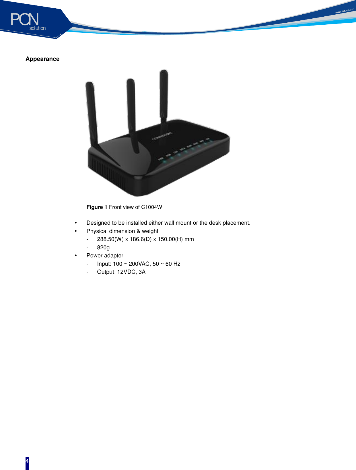
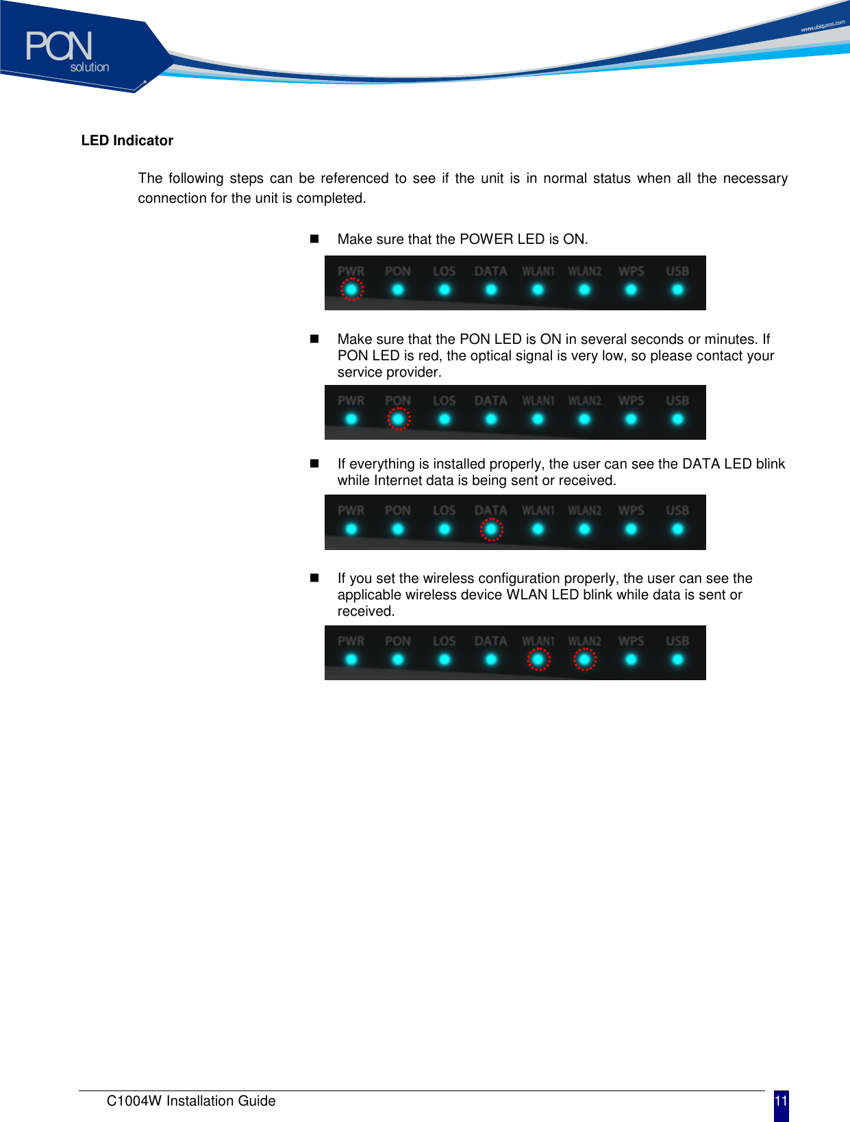
![solutionPON C1004W Installation Guide 3 Product Introduction C1004W is a single family unit type ONU which has a 10G EPON uplink and 4 Gigabit Ethernet ports for service as well as dual band WiFi interfaces. Each service port can support upto 1 Gbps bandwidth meanwhile WiFi interface supports IEEE 802.11 b/g/n/ac. Besides, OAM functions like remote detection/configuration via ACS, web configuration and QoS control features are also obtainable for smoother operation and maintenance. Features Various speed combination supported Diverse Downstream/Upstream speed sets for the uplink segment are available - 10Gbps / 10Gbps - 10Gbps / 1Gbps - 2Gbps / 1Gbps (Turbo mode) - planned - 1Gbps / 1Gbps - planned Uplink segment means the portion between OLT and ONU. [Note] 2Gbps / 1Gbps (Turbo mode) and 1Gbps / 1Gbps are only available provided that appropriate optic module is equipped at the corresponding OLT port. Compliant to cablelab’s DPoE specification Right for the MSOs who want to migrate to EPON technology Management via efficient OAM Remote detection and configuration by way of TR-069 (planned) EPON OAM Authentication Charging Dualband wireless access in concurrent manner IEEE 802.11 ac as well as b/g/n are supported. - At 2.4 GHz: IEEE 802.11 b/g/n - At 5 GHz: IEEE 802.11 ac Local Configuration via web GUI For monitoring and settings](https://usermanual.wiki/CommScope-of-North-Carolina/C1004W2/User-Guide-2745172-Page-5.png)
![solutionPON 18 Advanced Setup / WAN Service You can create the Interface for various WAN service based on the assigned WAN Physical Port. To create WAN Service Interface, click [Add] button on [WAN Service Setup Display].](https://usermanual.wiki/CommScope-of-North-Carolina/C1004W2/User-Guide-2745172-Page-20.png)
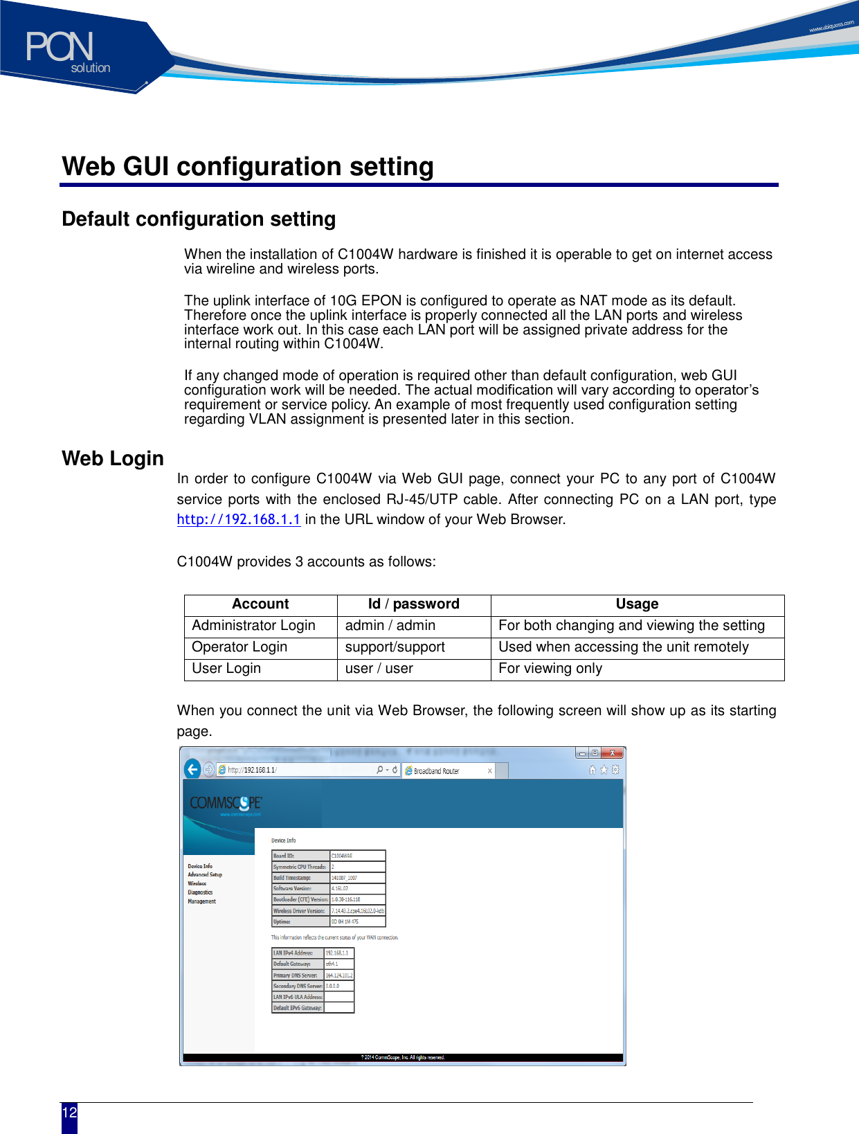
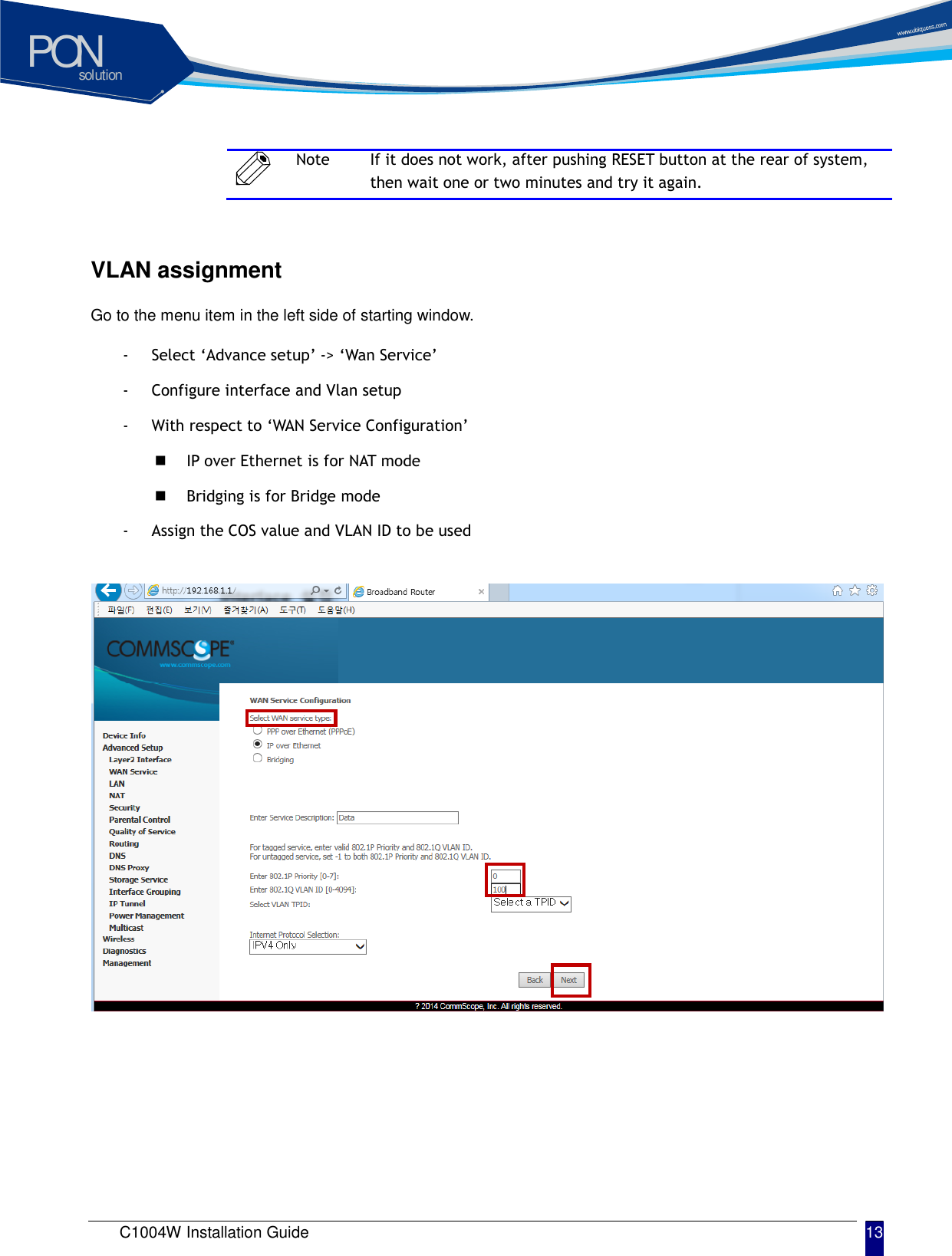
![solutionPON C1004W Installation Guide 19 If you click [Next] button, you can assign VLAN ID about 802.1Q and a priority about WAN service type and 802.1P. Note In case of assigning as Untagged Service from WAN Service Interface, you must set it as ‘-1’.](https://usermanual.wiki/CommScope-of-North-Carolina/C1004W2/User-Guide-2745172-Page-21.png)
![solutionPON 20 If you click [Next] button, you can set IP about WAN Service Interface. When the system needs to obtain an IP address automatically from DHCP server connected with WAN network, select [Obtain an IP address automatically] radio button. When the system uses the static IP address on WAN Service Interface, select [Use the following Static IP address]. Then set Static IP Address, Subnet Mask and Gateway IP Address. If you click [Next] button, you can enable NAT and Multicast function on the WAN service Interface.](https://usermanual.wiki/CommScope-of-North-Carolina/C1004W2/User-Guide-2745172-Page-22.png)
![solutionPON C1004W Installation Guide 21 If you click [Next] button, you can assign Default Gateway about WAN Service Interface. If you click [Next] button, you can set DNS Server about WAN Service Interface.](https://usermanual.wiki/CommScope-of-North-Carolina/C1004W2/User-Guide-2745172-Page-23.png)
![solutionPON 22 When the above procedure is done, it shows the information about WAN Service to be applied finally. When you click [Apply/Save] button, the information of the set WAN Service Interface is listed and it is done about WAN Service Interface. Note If you change 802.1P, 802.1Q on the created WAN Service Interface, you must register again after deleting WAN Service. Note In case that you assign 802.1Q VLAN-ID individually on the several WAN Service and do grouping LAN Interfaces, refer to Interface Grouping setting on Advanced Setup Section.](https://usermanual.wiki/CommScope-of-North-Carolina/C1004W2/User-Guide-2745172-Page-24.png)
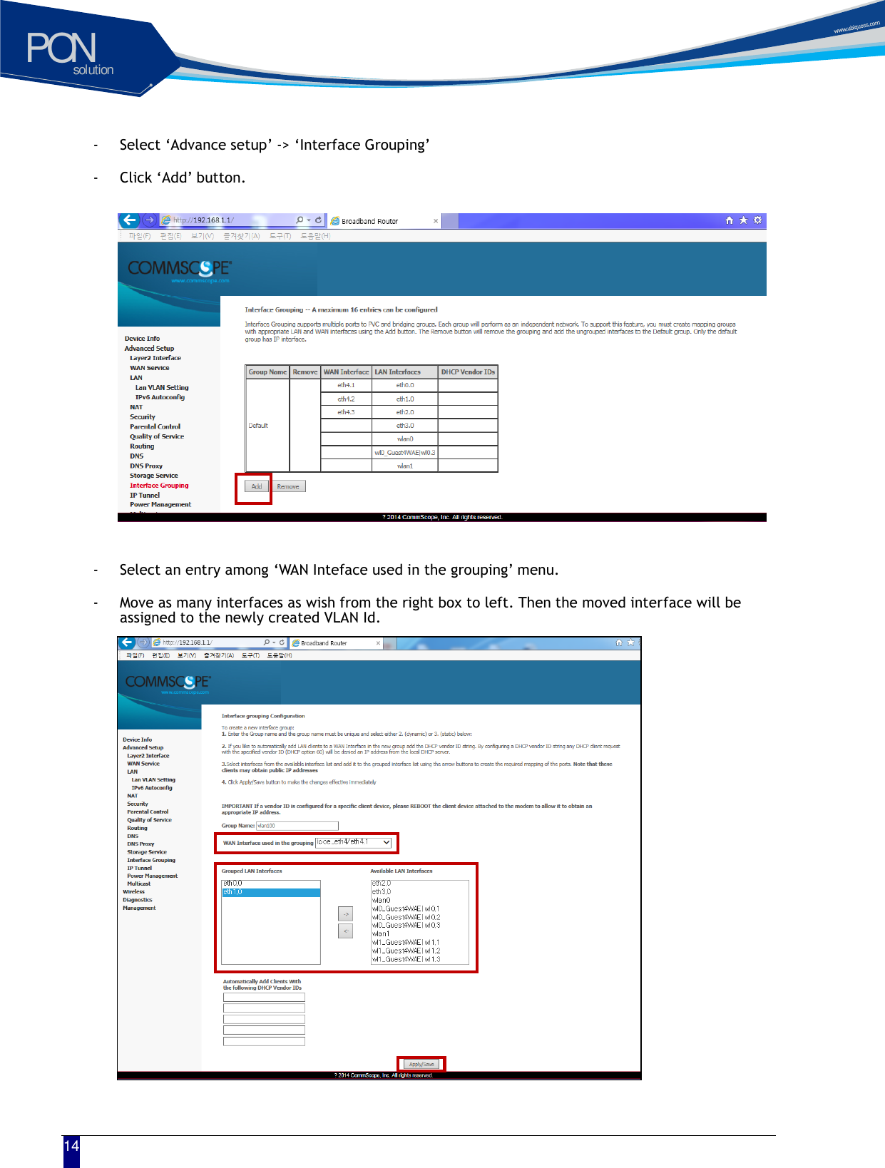
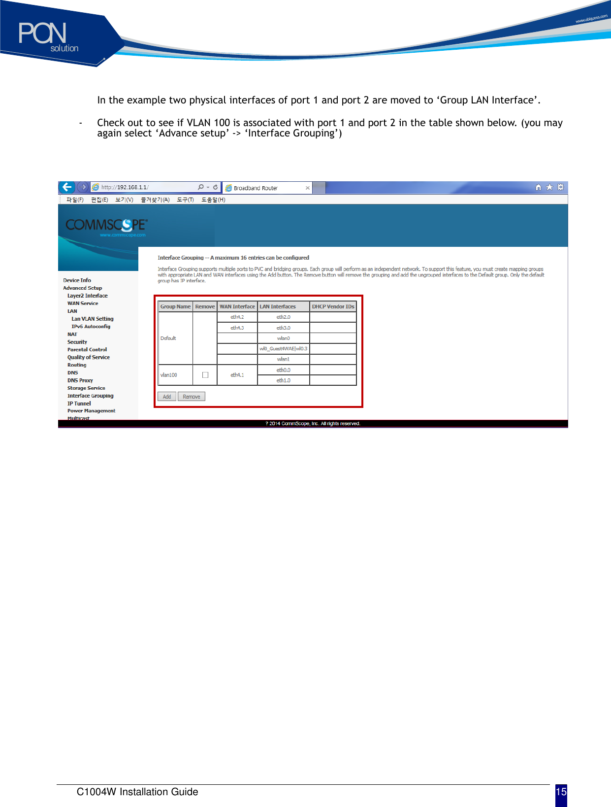
![solutionPON C1004W Installation Guide 23 Advanced Setup / Interface Grouping By creating several groups, you can manage several LAN Interfaces with Interface grouping provided from Advanced setup. By default, one default group includes all LAN Interfaces. To create Interface Group, click [Add] button on [Interface Group Display] Set Group Name with easy name to acknowledge. To set WAN Interface for using to create Group, select list box. After selecting WAN Interface, select LAN Interface for including to group to create. Select LAN Interface to move on the [Available LAN Interfaces] BOX. If you click arrow button, it moves to the [Grouped LAN Interfaces] BOX.](https://usermanual.wiki/CommScope-of-North-Carolina/C1004W2/User-Guide-2745172-Page-25.png)
![solutionPON 24 After the creating Group by clicking [Apply/Save] button, the Group is created like following screen. Note To process incoming traffic after applying VLAN ID per each Group, one WAN interface per Group system is applied. Thus, to set like the following screen, you must add WAN interface before creating Group. Note To know the way of adding WAN Interface, refer to [Advanced Setup / WAN Service].](https://usermanual.wiki/CommScope-of-North-Carolina/C1004W2/User-Guide-2745172-Page-26.png)