Command Technologies HF2500MAGNUM Non-Broadcast Transmitter User Manual 2500Manual
Command Technologies Inc Non-Broadcast Transmitter 2500Manual
User Manual and Schematics
COMMANDER HF-2500/
HF-2500 MAGNUM
LINEAR AMPLIFIER
MADE IN THE U.S.A. BY HAMS FOR HAMS
COMMAND TECHNOLOGIES, Inc.
15719 CR 2.50
P. O. BOX 326
EDON, OHIO 43518-0326
419 459-4689
800-736-0443
THE COMMAND TECHNOLOGIES PHILOSOPHY
The company was founded upon the guiding principle of providing
amateur radio operators with better equipment at a lower cost.
That principle is evident in the company's products which have become
known throughout the world for their superior value.
Value is defined by the company as a ratio of quality plus performance
over cost. The higher the quality and/or performance or the lower the
cost, the better the value.
Obviously, the limits of each parameter of the equation are subjective.
For the company, quality limits are those which provide longevity and
unquestioned performance benefits to the user without unnecessary
cost burden. Performance is partly defined by governmental
regulations and partly by the company's integrity of specifications. For
example, power for Command Technologies linear amplifiers is
specified by continuous carrier ratings - solid, meaningful figures which
can be translated into benefits in the real world of amateur radio.
State-of-the-art technology has come to be a trite phrase, meaning
different things to different people. To the company, it means today's
proven technology, not gimmicks, which offer a facade with little of
worth, or need, behind it. We may push the leading edge of technology
in various ways, but it will be founded upon its value to the user in
terms of performance and cost.
We appreciate your purchase of a Command Technologies product
and assure you of continued factory support of your investment at all
times.
Sincerely,
Patrick J. Stein
N8BRA
SPECIFICATIONS
COMMANDER HF-2500/
HF-2500 MAGNUM
LINEAR AMPLIFIER
Band Coverage: 160, 80, 40, 20, 17, and 15 meter amateur radio bands,
12 and 10 meter Export model; also useable in U.S.A.
upon proof of proper license.
Types of Emissions: SSB, FM, CW, AM, RTTY, SSTV
Driving Power Required: 40 to 60 watts nominal at rated continuous
carrier output
Maximum Output Power: 1500 watts Continuous Carrier, 1500 watts CW,
1500 watts Single Side Band
Duty Cycle: 100 percent in Amateur service at 1500 watts output power
Harmonic Suppression: Exceeds all F.C.C. Requirements
Keying: Requires contact closure of sinking +20 v dc at 300 ua. dc.
Input Impedance: 50 ohms unbalanced
Output Impedance: 50 ohms unbalanced: SWR 2:1 or less
Metering: Plate Voltage & Plate Current (switchable), Grid Current (continuous)
A.L.C.: Negative going, adjustable from rear panel
Front Panel Controls: Plate Voltage & Current Switch, On/Off Switch, Tune,
Load, Band Selector Switch
Rear Panel Controls: Tuned Input Adjustment, A.L.C. Adjustment, R.F. Input,
R.F. Output A.L.C. Output, Keying, +12v dc Auxiliary
Source, Ground Connection, Line Cord, Fuse
Tube Complement: Two Eimac 3CPX800A7 Ceramic/Metal Triodes
Power Requirement: 200 / 234 Vac, 50/60 hz, 20 amperes
Introduction
The Commander HF-2500/HF-2500 MAGNUM are class AB2 linear power
amplifiers. They have been designed for operation on all amateur frequencies from
1.80 Mhz to 21.450 Mhz excluding the 30 meter band. Two Eimac 3CPX800A7
ceramic-metal triodes, configured in a grounded grid circuit, allows for conservative
operation at 1500 watts continuous carrier output. A pressurized forced air cooled
chassis, including the high voltage supply, insures cool operation with high duty
cycle emission modes. The output circuit utilizes extra heavy duty components with
reduced ratio drives on all tuning controls. Easily accessed rear panel controls
allow for operator adjustment of input VSWR and ALC. An automatic time delay
circuit, insures proper cathode conditioning before R.F. drive can be applied. A
protection resistor, located in the high voltage B+ circuit, protects the tube in the
event of an internal tube arc. Metering function includes plate voltage, plate current,
and grid current.
Unpacking instructions
Carefully remove the Commander HF2500/HF-2500 MAGNUM from its shipping
carton. Make sure no shipping damage exists. If damage exists, NOTIFY THE
DELIVERING CARRIER IMMEDIATELY. Describe fully the damage. Do not
destroy the shipping carton or packing material. In the event you need to return your
unit or wish to ship it to another location, the original shipping carton and packing
material works best. Please retain your sales invoice. Should you ever need
warranty service, it may be required to prove your date of purchase.
!! WARNING !!
CONTACT WITH VOLTAGES
IN THIS AMPLIFIER CAN BE
!!! FATAL !!!
Cautions and Warnings
Do not attempt any type of service or repair on this Amplifier without first removing
the AC power and allowing at LEAST 60 MINUTES FOR THE HIGH VOLTAGE
CAPACITORS TO BLEED OFF !
Make no attempt to put this Amplifier in service with the top or bottom covers
removed. CONTACT WITH VOLTAGES IN THE CABINET CAN BE FATAL !
Never attempt operation without first connecting your amplifier to an appropriate
antenna or dummy load. The antenna SWR should not exceed 2:1. The dummy
load should have an impedance of 50 ohms with sufficient power handling capability.
DAMAGE TO THE AMPLIFIER MAY RESULT IF OPERATED WITHOUT A
CONNECTION TO A PROPER LOAD.
Never operate this amplifier without the ALC connected. Most modern transceivers
have sufficient output power to seriously overdrive this amplifier. THIS MAY
RESULT IN DAMAGE TO EXPENSIVE COMPONENTS SUCH AS THE
3CPX800A7 TRIODE TUBES.
NEVER OPERATE THIS AMPLIFIER WITHOUT AN EARTH GROUND
CONNECTED TO THE REAR PANEL GROUND TERMINAL.
Do not obstruct the ventilation holes located on the top, bottom, and sides of the
cabinet. These holes provide sufficient intake and exhaust of cooling air.
SEVERE OVERHEATING AND SERIOUS DAMAGE WILL RESULT IF
SUFFICIENT VENTILATION IS NOT PROVIDED.
If any problem occurs which can not easily be corrected, contact the manufacturer
for assistance.
Accessory warnings
Your new Commander HF-2500/HF-2500 MAGNUM has the capability of 1500 watts
output continuous carrier without time limit. Many accessories such as power
meters, traps. and baluns have power ratings for the old 1,000 watt input (600 watt
output) power restriction. The 1500 watt continuous carrier output capability of the
Commander HF-2500/HF-2500 MAGNUM may destroy these accessories. If you
are in doubt about the power handling capability of a particular accessory, contact
the original manufacturer, or use the accessory at reduced output power. When in
doubt , do not use an accessory with this amplifier. FAILURE OF AN
ACCESSORY MAY CAUSE DAMAGE TO THE COMMANDER HF-2500/HF-2500
MAGNUM.
COMMAND TECHNOLOGIES INC.
15719 CR 2.50
P.O. BOX 326
EDON, OHIO 43518
TEL: 419-459-4689
TRANSFORMER INSTALLATION
When mounting the hypersil transformer, place the HF-2500\HF-2500
MAGNUM so the front panel faces your body. Align the transformer so
the Danger High Voltage label reads right. The wire leads coming out
of the transformer should be to the rear and the connector to the right.
place the transformer in the unit aligning the transformer's mounting
holes to the mounting holes on the bottom of the chassis. Place the 1/4
- 20 screws threw the mounting holes and chassis and secure with the
1/4 - 20 nuts and washers. Connect the male-female "mate & lock"
connector. Push hard to insure that the two halves are locked together.
The transformer should now be installed and ready for use.
TUBE INSTALLATION
Carefully remove the 3CPX800A7 tubes from their shipping carton.
This carton was located in the area where the transformer was
installed. Place the tubes in the tube sockets with the proper pin
alignment. If you have maintained the proper pin alignment, the tubes
should go into their sockets easily. If you have to use undue pressure
to insert the tubes, you may have the wrong pin alignment or one of
the pins may be bent. If necessary straighten pins with needle nose
pliers and reinstall. Install the parasitic chokes on the tube caps and
replace the top and bottom covers. When you reinstall the top and
bottom covers it may be necessary to use an awl to align the screws.
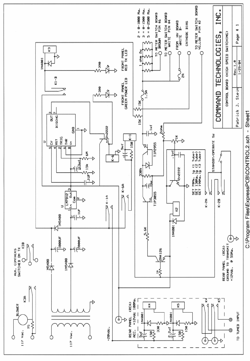
Connection Diagram
High Speed Switching
Connect the RF output of your transceiver to the RF IN connector on the rear
of the HF-2500\HF-2500 MAGNUM with 50 ohm coax. Connect the existing station
antenna system to the RF OUT connector on the HF-2500\HF-2500 MAGNUM with
RG-8 type coax. Connect the RELAY phono jack on the rear
of the HF-2500\HF-2500 MAGNUM to the normally open terminal of the RELAY
jack on your transceiver. The RELAY jack on the HF-2500\HF-2500 MAGNUM has
positive 20 VDC open circuit and requires the sinking of 300 UA of current when
pulled to ground. Connect as short a ground lead as possible from a good earth
ground to the GROUND post on the HF-2500\HF-2500 MAGNUM. The 12 VDC
phono jack on the HF-2500\HF-2500 MAGNUM rear panel provides 12 VDC at 100
MA maximum to operate external accessories or dial lamps. Connect the ALC
phono jack to the ALC connection on your transceiver using a shielded type cable.
Consult your transceiver manual for proper ALC connection details.
TUNING PROCEDURE
1. Set the front panel controls to the following positions:
ON - OFF Switch...................OFF
STANDBY - OPERATE........STANDBY
METER SWITCH...................Vp
BAND SWITCH......................DESIRED BAND
TUNE CONTROL...................LOG SCALE ON DATA SHEET
LOAD CONTROL...................LOG SCALE ON DATA SHEET
2. After you have preset the above controls and the amplifier is
properly connected to a suitable load, switch the ON - OFF to the on
position. The blower should be running and the meter lamps should
also be lit. The meter should read a plate voltage of approximately
2600 volts DC. (3400v on HF-2500 MAGNUM)
3. After a little more than 2 minutes the green power lamp should
come on signifying the amplifier is ready for operation. Place the meter
switch in the Ip position and the standby - operate to the operate
position. Key the exciter with no rf drive applied. The red transmit lamp
should light, and an indication of approximately 250 ma plate current
on the meter. Apply 5 to 10 watts of rf drive, the plate current should
rise slightly. If the plate current rises above 600 ma. reduce drive.
Adjust the tune control for a peak on the grid meter and maximum
output as indicated on an external wattmeter.
4. Adjust the load control for maximum output as indicated on an
external wattmeter. Next, while increasing the drive in small increments
adjust the load control counter clockwise for maximum output and to
keep the grid current below 60 ma. Readjust the tune control clockwise
to again peak the reading on the grid meter. If the meter rises above
60 ma quickly reduce drive and adjust the load control
counterclockwise to reduce grid current. Never exceed 100 ma of grid
current. Repeat these adjustments as required to achieve the desired
output up to 1500 watts. Note that when increasing output power the
tune scale will always read higher and the load will read lower. Also the
supplied inspection sheet has all the of these settings and they should
be used as a guide for this procedure. If your settings vary widely from
these you have something wrong and should start over.
TUNING PROCEDURE CONTINUED
5. If your planned operation is on SSB, you should adjust the load
control slightly counter-clockwise, reducing the output slightly about 30
to 50 watts. This adjustment is necessary to insure that the amplifier is
sufficiently loaded to handle the plate current peaks caused by the
complex voice patterns during SSB operation. Nominal plate and grid
current readings during SSB operation will be about 30 to 40% of the
key down CW readings.
CAUTION: THE TUNE AND LOAD AIR VARIABLE CAPACITORS MAY ARC IF
MAXIMUM DRIVE IS APPLIED BEFORE THE AMPLIFIER IS PROPERLY TUNED.
ALWAYS FOLLOW THE DECRIBED TUNE UP PROCEDURE TO AVOID
CAPACITOR ARCING. ARCING MAY ALSO OCCUR IF YOU ATTEMPT TO TUNE
INTO AN ANTENNA WITH A VSWR GREATER THAN 2:1.
If you should need any further assistance tuning this amplifier, feel free to call
us here at 1-800-736-0443 and our staff will be happy to help you. If you are
outside the United States we are available at 011-419-459-4689.

Theory Of Operation
The Commander HF-2500\HF-2500 MAGNUM uses a pair of C.P.I.
Eimac 3CPX800A7 ceramic/metal triodes in a class AB2 grounded grid
configuration. Nominal drive power of 50 to 60 watts will deliver 1500
watts of clean RF output power. This amplifier will operate on the
following amateur bands: 160,80,40,20,17, and 15 meters. (12 and 10
meters with authorized modification) . File copy of proper license is
required for these instructions. Operation of this amplifier on the 11
meter (citizen band) is not possible as this unit employs RF chokes
with series resonance within this band. Attempted operation will cause
serious damage that will not be covered under warranty.
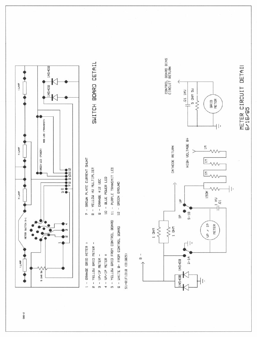
Metering Functions
The Commander HF-2500\HF-2500 MAGNUM has two illuminated
panel meters. The Grid Current meter provides a continuous reading
of the 3CPX800-A7 grid current. The meter scale is 2 MA per division,
the range is 0 to 200 MA. DO NOT EXCEED 100 MA OF GRID
CURRENT. DAMAGE TO YOUR TUBES COULD RESULT. Under
typical operating conditions the grid current will be 30-50 MA . Plate
voltage and Plate current are shown on the second meter. A function
switch on the front panel switches the meter from plate voltage to plate
current. Plate current is shown on the top scale. Each division is 30
MA, and full scale is 1,500 MA. The typical plate current under
nominal rated output (1500 Watts) should range from 1000 MA to 1200
MA on the HF-2500, and 700 MA to 800 MA on the HF-2500
MAGNUM. with an absolute maximum of 1500MA. for SSB. Plate
voltage is indicated on the bottom scale with each division reflecting
.06 KV. The scale has a range from 0-3.0 KV (0-3.5 KV HF-2500
MAGNUM). The nominal no-load plate voltage on the HF-2500 should
read approximately 2,600 volts, with 3,400 volts on the HF-2500
MAGNUM. Plate voltage under nominal full load should read
approximately 2,300 volts (3,200 volts HF-2500 MAGNUM).
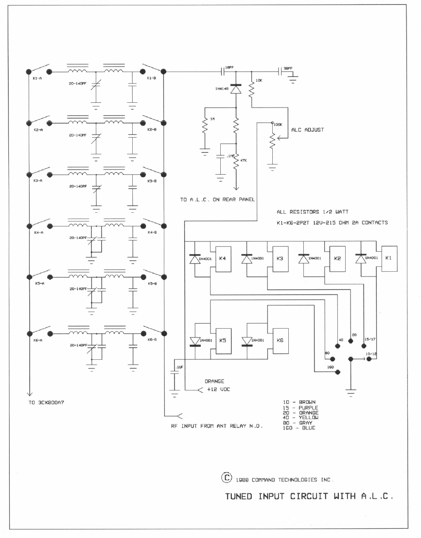
TUNED INPUT CIRCUITS
The tuned input circuits utilize an L-C-L or "T" impedance matching
circuit with a high "Q" design. These circuits employ RF phase
compensating capacitors to reduce intermodulation products. The use
of mica trimmer type capacitors allows adjustments to precisely match
the transceiver to the amplifier. The rear panel provides easy access to
these trimmer capacitors. A front panel switch selects the proper input
filter by grounding an associated relay coil.
Tuned Input Adjustments
Your Commander amplifier has mica trimmer capacitors which are
easily accessed thru holes located on the rear panel. The tuned input
circuits are factory tuned and should not require any readjustment.
You can easily make adjustments for any change in your preference
for operating frequency range. Also, slight adjustments may be
necessary because of slight variances in impedances between your
transceiver and the tuned input circuitry of the amplifier.
1. Install a SWR meter between the transceiver and the amplifier.
2. Make sure the Operate/Standby switch is in the operate position
and the band switch is set to the same band as the one for which you
are making adjustments. Your amplifier should also be properly tuned
and loaded.
3. Apply drive and observe the SWR, and adjust the trimmer
capacitor for minimum SWR. Be careful not to overdrive the amplifier.
4. Repeat this procedure each band.
AUTOMATIC DRIVE LIMITING CONTROL
An adjustable automatic level control (ALC) circuit limits the peak
output power. When properly set, this circuit insures that the amplifier
can not be overdriven. Rear panel access allows for easy manual
adjustment . A sample of the RF input derives the ALC voltage.
Additionally this amplifier has an RF negative feedback resistance in
the cathode circuit to help cancel excessive RF drive without reducing
the amplifier's gain.
A.L.C. ADJUSTMENTS
Your transceiver’s internal ALC will maintain linearity. The amplifier's
ALC will prevent overdriving the amplifier. The HF-2500\HF-2500
MAGNUM's ALC circuit was designed for negative going ALC voltage.
Proper adjustment is as follows:
1. Use an insulated tool when making these adjustments.
2. Tune the amplifier for operation on the 20 meter band for full
1500 watts output.
3. With your transceiver set for 20 meter SSB operation, set the
transceiver's microphone gain for normal operation as specified in its
owners manual.
4. While speaking louder than normal into the microphone, adjust
the ALC POT on the rear panel thru the access hole. Adjust for 1500
watts maximum output as indicated on an external peak reading
wattmeter. If an average reading wattmeter is used, adjust for
approximately 750 watts output on voice peaks.
5. On some of the late model transceivers this adjustment can be
adjusted in the CW position. On these models (with your output at 1500
watts) simply adjust for a slight drop in output.
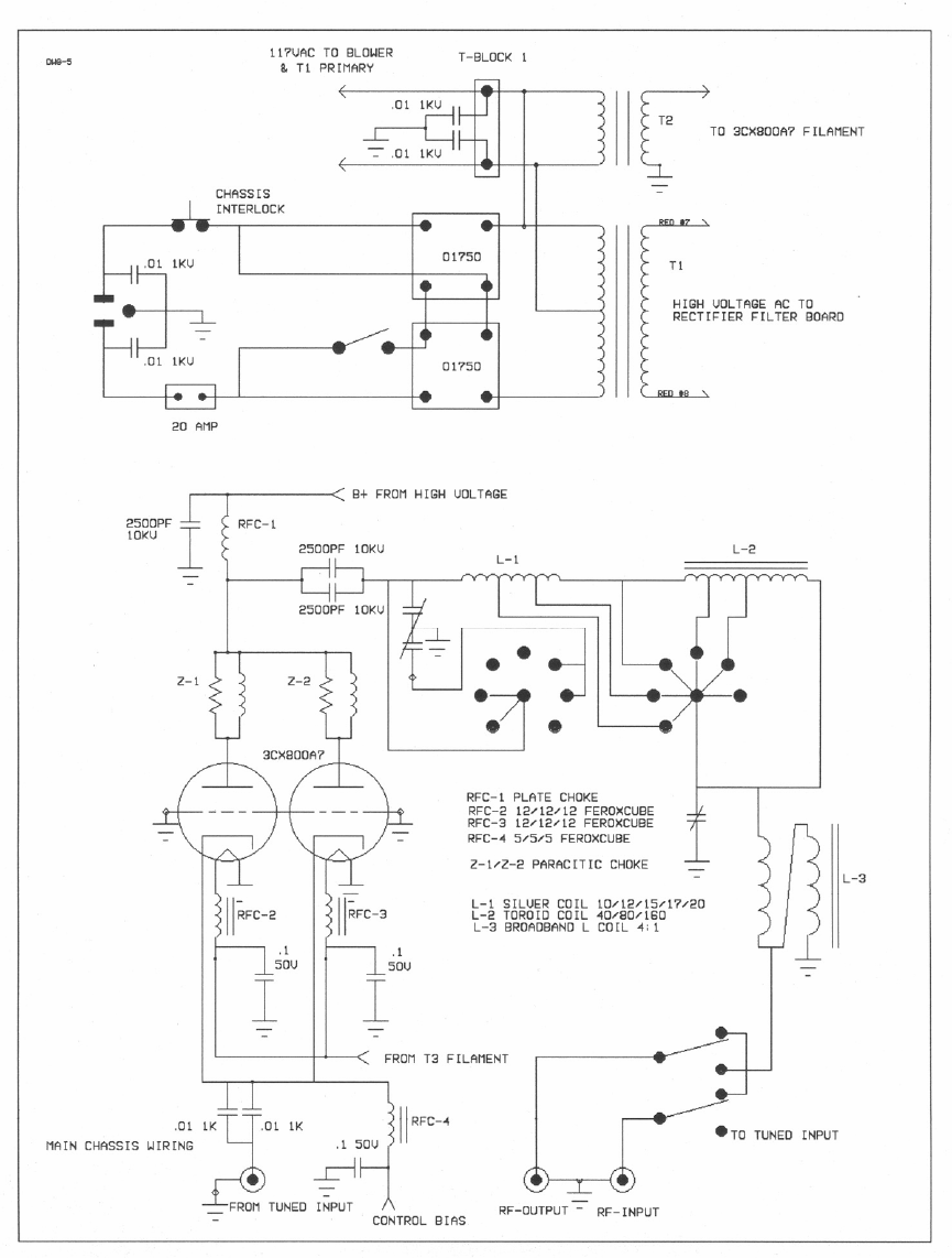
OUTPUT FILTER CIRCUIT
The PI variable network filter transforms the plate load impedance from
approximately 2,500 ohms down to 200 ohms, Two air variable
capacitors, and an associated inductor, accomplish this transformation.
A heavy duty band switch selects the proper inductance from two high
"Q" inductors. Each inductor contains taps for the desired band. A
design "Q" of 14 allows for good harmonic attenuation on all bands.
The utilization of a special reactance tuned ferrite core, 4 to 1
transmission line transformer, transforms the nominal 50 ohm antenna
impedance up to the 200 ohm output of the PI circuit. This also
provides further harmonic attenuation of the output, in the same
manor, as an "L" coil in a Pi - L network.
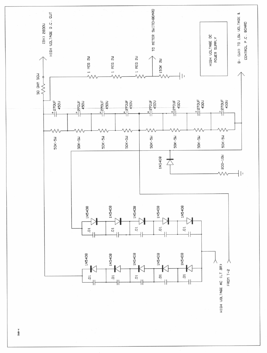
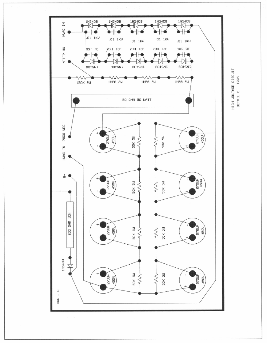
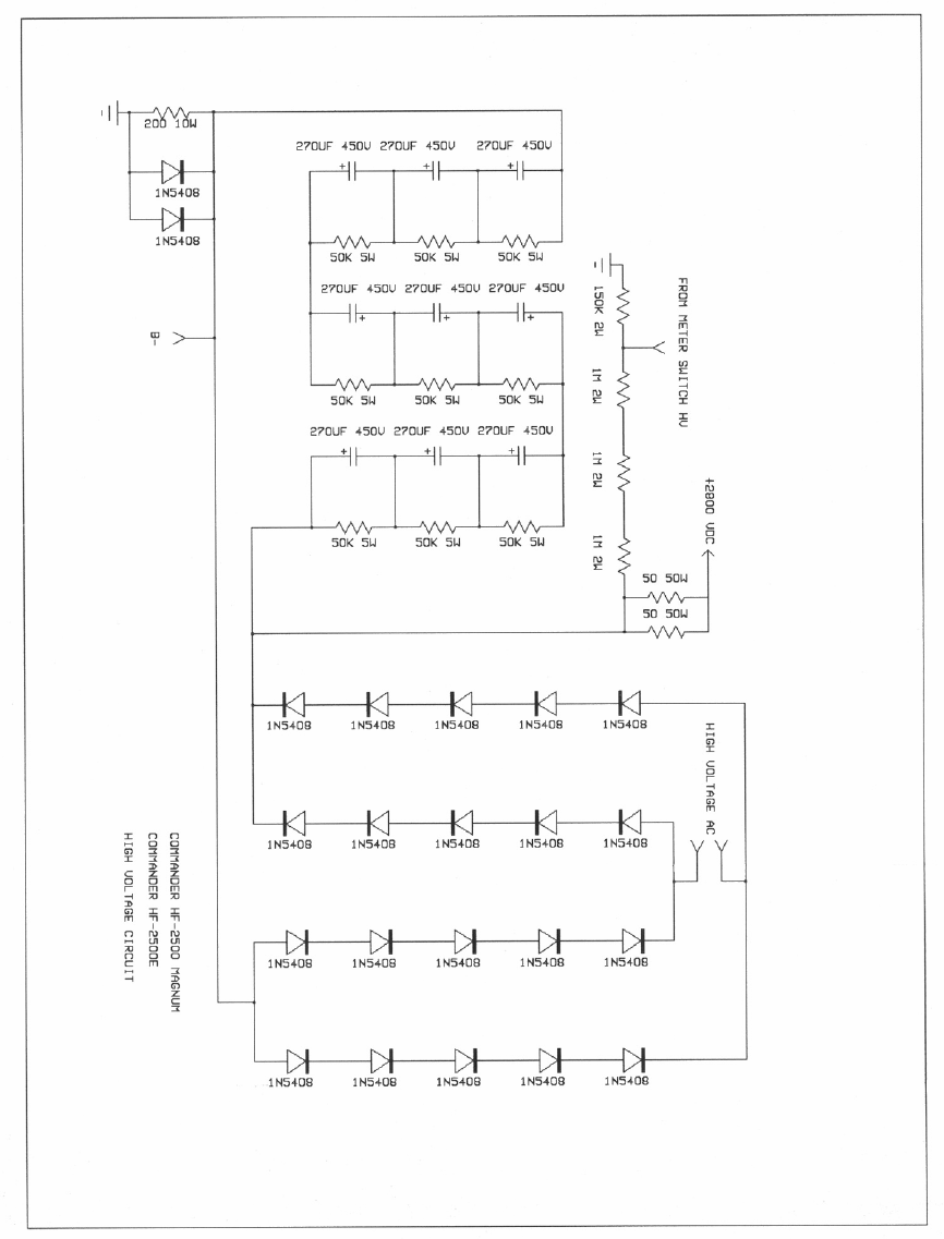
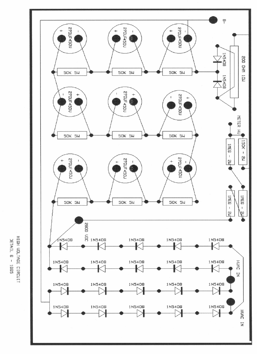
HIGH VOLTAGE SUPPLY
The high voltage supply operates from 200/234 Vac. 20 ampere line.
The primary of the high voltage transformer is switched on/off with
solid state relays, that only conduct when the phase angle of the AC
power line is at zero degree crossover. This minimizes line surge and
inrush current, while the high voltage filter capacitors charge. The front
panel on/off switch activates the solid state relays with 2ma AC to turn
the unit on. Approximately 900 volts AC is applied to a full wave
voltage doubler rectifier circuit. (On the HF-2500 MAGNUM, 2400 volts
AC is applied to a full wave bridge). This supplies approx. 2600 volts
DC to the 3CPX800-A7 anode. Metering of the tube anode and grid
current is accomplished by shunt resistors located in the negative
return of the 3CPX800-A7 cathode. Plate voltage metering is
accomplished by a resistor multiplier network in the B+ line of the high
voltage circuit.
Limited Warranty
Command Technologies, Inc. warrants to the original purchaser, that our
Commander Amplifiers shall be free from defects in material, except Eimac
3CPX800A7 tubes, or workmanship for five (5) years from the date of original
purchase. Tubes are covered by warranty granted from their manufacturer.
During the warranty period, Command Technologies, Inc. will correct defects in
material and workmanship. Original purchaser will pay all shipping charges.
Command Technologies, Inc. provides warranty parts and services according to the
following schedule:
1st year............................100% parts and labor
2nd year.............................50% parts and labor
3rd,4th and 5th year..........25% parts and labor
to obtain such warranty service, the purchaser must:
1. Notify Command Technologies as soon as possible after the discovery of
possible defect of:
a. The model number and serial number
b. Approximate date of purchase
c. A detailed description of the problem
2. Deliver the product to Command Technologies service facility, or ship the
same in its original container or equivalent, fully insured and shipping
charges prepaid.
Correct maintenance, repair, and use are important to obtain proper performance
from this product. Therefore, carefully read the Instruction Manual. This warranty
does not apply to any defect that Command Technologies, Inc. determines is due to
:
1. Improper maintenance or repair including the installation of parts or
accessories that do not conform to the quality and specifications of the
original parts.
2. Misuse, abuse, neglect or improper installation.
3. Accidental or intentional damage.
All implied warranties, if any, terminate five years form the date of the original
purchase.
The foregoing constitutes Command Technologies entire obligation with respect to
the product, and the original purchaser and any user or owner shall have no other
remedy and no claim for incidental or consequential damages. Some states do not
allow limitations on how long an implied warranty lasts or do not allow the exclusion
or limitation of incidental or consequential damage, so the above limitation and
exclusion may not apply to you.
This warranty gives specific legal rights, and you may also have other rights which
vary from state to state.