Communication Components BDA-1819-10 PCS PICO CELL BOOSTER User Manual BDA181910 Users Guide
Communication Components Inc PCS PICO CELL BOOSTER BDA181910 Users Guide
user manual

Page#1 of 2
PICO CELL Booster
CCI Model Number BDA-1819-10
USER’S GUIDE
Product Description:
BDA-1819-10 PICO CELL Booster:
The CCI GSM/EDGE PICO CELL Booster is Bi-directional coupler that consists of both
the uplink and downlink channel. The downlink is capable of generating a minimum
10 Watt GSM/EDGE signal. The uplink Low Noise Amplifier has the minimum of
15dBm output power with 2 dB of noise figure. It has the build in DC power supply
that will provide the whole unit. The PICO CELL Booster increases the overall
coverage area while improving performance.
Operation Description:
The BDA-1819-10 PICO CELL Booster is designed to supply nominal output power of
10 Watt GSM/EDGE. Although the gain of the PICO CELL Booster is fixed, the output
can be adjusted by the setting the input power level.
Operation and Installation Instructions:
The following instructions should be followed when installing the unit in service:
• Apply a 120VAC input voltage to the AC connector of the PICO CELL Booster
Module.
• Apply a GSM/EDGE signal of up to +15dBm to each RF input port of the PICO
CELL Booster Module.
• The PICO CELL Booster Module will provide approximately 25dB RF Gain on
the downlink and approximately 9dB RF Gain on the Uplink
• Check the RF output to insure the proper downlink output power is present.
{Approximately 10 Watts (40dBm) }.
COMMUNICATION
COMPONENTS INC
Extending Wireless Coverage 89 Leuning Street Phone: 201-34
2
-333
8
2nd Floor Fax: 201-342-3339
S
outh Hackensack, NJ 07606 www.cciproducts.com
Page#2 of 2
• Adjust the input power level to insure the output power level is in compliance
with the values indicated in the table on page 2.
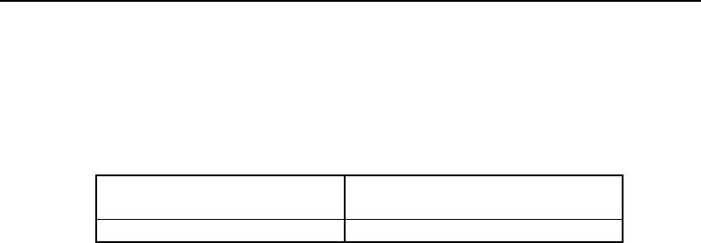
Setting the RF Output Power on the BDA-1819-10 Booster Amplifier
The RF output power is not adjustable on the PCS PICO CELL Booster Amplifier. The
user must adjust the RF input power to the PCS PICO CELL Amplifier such that the
RF output power level does not exceed the levels shown below in order for the RF
output spectral emissions to be compliant with the FCC spurious emissions limit of -
13 dBm outside of the assigned frequency block.
Channel Center Frequency
(MHz)
Maximum RF 0utput
(Watt)*
1930.2-1989.8 10
* Note: The Maximum RF Output Power is after any passive losses after the Booster Amplifier such as
filters and cables.
This equipment complies with Part 24 of the FCC rules. Any changes or
modifications not expressly approved by the manufacturer could void the user's
authority to operate the equipment.
In order to comply with FCC rules for RF exposure, it must be observed that the
antenna connected to this equipment be fixed on an outdoor structure and that it
must have a minimum separation distance of 3 meters between it and any
person."
This equipment has been tested for single channel operation only and should not
be used for multi-carrier operation.