Communication Components CE-1819-100MC PCS Cell Extender User Manual PCS CDMA MulticarrierCell Extender
Communication Components Inc PCS Cell Extender PCS CDMA MulticarrierCell Extender
Users Manual
Technical Description
General Info and
Technical Description
1
Electrical Specifications
Mechanical Specifica-
2
Block Diagram 3-4
Mechanical Diagram 5
Contents
CCI’s Multi-channel CDMA Cell Extender is designed to improve overall site performance by
boosting both forward and reverse link parameters in a balanced manner. The system is designed
to provide 100 Watts of usable CDMA output power per sector antenna and can serve up to three
sectors with two feeder antennas per sector. As such, a CE-1819-100MC system used in six car-
rier sector with 3 carriers per antenna can delivers 32 W per carrier.
The CE-1819-100MC was specifically designed for very simple interface with micro and mini base
stations without any need of retrofitting the original BTS equipment. The system can be pad
mounted at any convenient location or pole-mounted when site space is limited.
The Cell Extender system consists of two major blocks that can be easily connected during the
initial installation of the BTS or as a retrofit to an operational BTS. The tower top amplifier (TTA)
unit is mounted at the top of the tower next to the Antennas and is responsible for improving the
uplink signal from mobile users and increasing the receive sensitivity of the BTS. The TTA is
housed in a moisture proof NEMA 4X enclosure and contains low noise receive amplifiers and du-
plexers. The TTA is powered via DC power that is coupled onto the center conductor of the coax
line. It also communicates is operational and alarm status three multi-carrier sectors via the coax
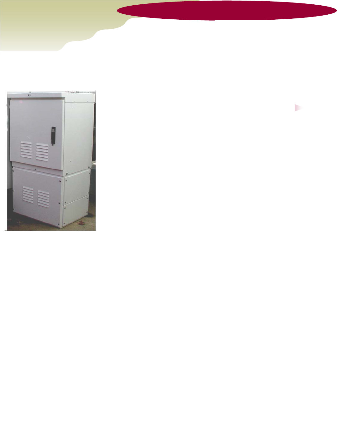
line. The Ground Level Unit (GLU) is an outdoor cabinet designed to serve up to three sectors
with up to six CDMA carriers per sector. Each sector section consists of high power Duplexers,
multi-channel power amplifiers, gain control and bypass circuitry which is activated in case of fail-
ure of any critical component of the system. CCI’s Multi-channel CDMA Cell Extender employs a
unique BTS transmit power recovery technology (patent pending) that allows up to a 25% in-
crease in the efficiency of the system.
Communication Components Inc.
Tel: 201-342-3338
Fax: 201-342-3339
Email: sales@cciproducts.com
PCS Multi-Carrier CDMA Cell Extender
Model CE-1819-100MC
General Information Communication Components, Inc. PCS
CDMA Multi-carrier Cell Extender im-
proves the performance of CDMA Base
Stations (BTS) in indoor and outdoor lo-
cations, allowing for cost efficient imple-
mentation of high capacity radio net-
works. By increasing both the downlink
power and receive sensitivity, CCI’s Cell
Extender increases the overall coverage
area and improves the performance of the
site. The CE-1819-100MC provides up to
100 Watts of combined CDMA output
power per feeder line/antenna.
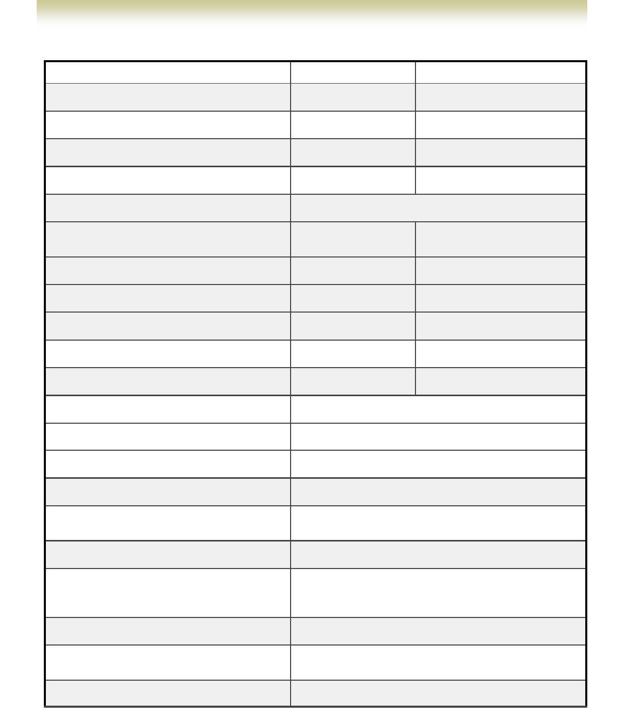
Multi-Carrier CDMA Cell Extender Electrical & Mechanical Specification
Communication Components Inc. PCS Multi-Carrier CDMA Cell Extender
Communication Components Inc.
Tel: 201-342-3338 Fax: 201-342-3339
Reverse Link Forward Link
A & D Blocks 1850-1870 MHz 1930-1950 MHz
B Block 1870-1885 MHz 1950-1965 MHz
C Block 1895-1910 MHz 1975-1990 MHz
E & F Blocks 1885-1895 MHz 1965-1975 MHz
Usable CDMA Composite Power Output: 100 Watts at output of cabinet
System Gain: Adjustable to
13 dB Max.
Adjustable to
10 dB Max.
Gain Variation: +/-0.5 dB Max. +/-0.5 dB Max.
Output Third Order IM3 @ 1.98 MHz 0ffset: N/A -55 dBc/30 kHz
Harmonics and Out of Band Spurious: N/A -13 dBm Max.
1 dB Compression Point: +15 dBm Min. +56 dBm Typ.
Input /Output VSWR: 1.5:1 Max. 1.5:1 Max.
Up-Link-Down-Link Isolation: 80 dB
System Noise Figure: 2.0 dB Max.
Power Requirements: 110 or 220 VAC; 1 Hour Battery Backup included
Power Consumption: 1 KW Max per Sector
Dimensions 12”L x 5.5” W x 3”D - Tower Top Unit
77”H x 24”W x 21”D - Ground Level Unit
Enclosure NEMA 3R Weather Proof Cabinet
Connectors Input from BTS: N-Female
Output to hard line: 7 /16 DIN-Female
Tower Top Amplifier: 7/16 DIN-Female
Weight TTA -20 Lbs. Max., Ground Unit –200 Lbs Max.
Mounting TTA –antenna pipe, Ground Unit - 24”x24” pad or H-
frame mountable
Operating Temperature: -25° to +50° C Ambient
Page 2

Additional Information
Communication Components Inc. PCS 20W CDMA Cell Extender
The Cell Extender is designed to enhance both uplink and downlink limited applications and
will boost the performance of the BTS to increase the overall coverage area of the site.
There are four major applications for CDMA Cell Extenders:
1. Sector MOU Enhancement– Typically for fringe sectors with low traffic. The goal is cover-
age/traffic/MOU increase by increasing footprint and low capacity site substitution by using Cell
Extenders in the corresponding sectors of neighboring sites.
2. RSSI and Soft/Hard Hand-Off Enhancement– When signal in overlapping areas is too
weak for reliable hand-off, the Cell Extender is installed on two opposing sectors for improved
RSSI in the hand-off area. Dropped calls can also be improved in crossed terrain sectors.
3. In-Building and Outdoor High Speed 3G-Data Enhancement- Increased downlink power
and uplink sensitivity results in higher data rate throughput.
4. Forward Power Blocking (FPB) or Automatic Level Control (ALC) Mode Reduction-
Using Cell Extenders with proper Pilot/Traffic channel power partitioning and sector parameter
settings can significantly decrease the FPB without reducing traffic. This approach can delay
and, in some cases, eliminate the implementation of second carriers (F2).
Options
♦ 1A: Single Antenna
♦ 1S: Single Sector
♦ 2S: Two Sector
♦ 3S: Three Sector
♦ 04: Bypass Option
♦ AD: A & D Band Operation
♦ B: B Band Operation
♦ EF: EF Band Operation
♦ C: C Band Operation
Ordering Information
♦ Model CE-1819-100MC
FCC Information
A minimum separation distance of 2 meters between the transmit antenna and nearby persons
must be maintained. If this separation distance is not maintained, this device may not be in
compliance with FCC RF Exposure rules.
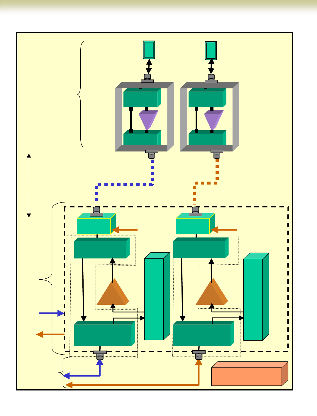
Single Sector Block Diagram: PCS Multi Carrier CDMA Cell Extender
Communication
PCS Multi-Carrier CDMA Cell Extender
Communication Components Inc.
Tel: 201-342-3338 Fax: 201-342-3339
Page 4
BTS
Pin=32 W
per Antenna
Tx, Rx Tx, Rx
3 Carriers
Sector
Antennas
3 Carriers
Ground
Level
LNA
DUPLEXER
Rx
Tx
A
DUPLEXER
Rx
Tx
LNA
DUPLEXER
Rx
Tx
A
DUPLEXER
Rx
Tx
TTATTA
Tower
Level
Pout=100 W
Combined
SINGLE SECTOR MODULE
PA
DUPLEXER
Rx TX
BTS
Bias-T DC
DUPLEXER
Rx TX
ANT
Attenuator Module
PA
DUPLEXER
Rx TX
BTS
Bias-T DC
DUPLEXER
Rx TX
ANT
Attenuator Module
Power Supply
Pout=100 W
Combined
Alarm
AC
Pout=100 W
Combined
BTS
Pin=32 W
per Antenna
Tx, Rx Tx, Rx
3 Carriers
Sector
Antennas
3 Carriers
Ground
Level
LNALNA
DUPLEXER
Rx
Tx
A
DUPLEXER
Rx
Tx
LNALNA
DUPLEXER
Rx
Tx
A
DUPLEXER
Rx
Tx
TTATTA
Tower
Level
Pout=100 W
Combined
SINGLE SECTOR MODULE
PA
DUPLEXER
Rx TX
BTS
Bias-T DC
DUPLEXER
Rx TX
ANT
DUPLEXER
Rx TX
ANT
Attenuator Module
PA
DUPLEXER
Rx TX
BTS
Bias-T DC
DUPLEXER
Rx TX
ANT
DUPLEXER
Rx TX
ANT
Attenuator Module
Power Supply
Pout=100 W
Combined
Alarm
AC
Pout=100 W
Combined
89 Leuning Street
South Hackensack, NJ 07606
Tel: 201-342-3338
Fax: 201-342-3339
Email: sales@cciproducts.com
Communication
Components Inc.
Www.cciproducts.com
Communication Components Inc.
Fax: 201-342-3339 Tel: 201-342-3338
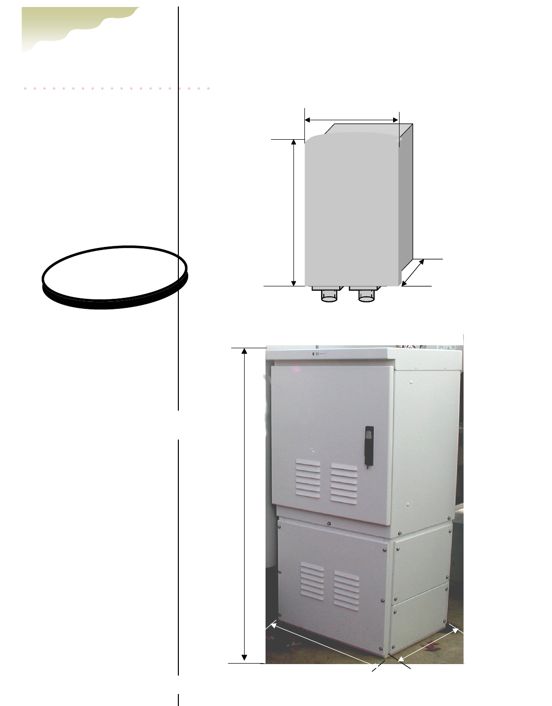
Tow er Top Unit
Outline: PCS Multi-Carrier CDMA Cell Extender
Ground Level Unit
77”
21”
27”
77”
21”
27”
Communication Components, Inc.
TTA-1819-MC
12”
3.5”
5.5”
Communication Components, Inc.
TTA-1819-MC
12”
3.5”
5.5”
Ordering Information:
♦ Model CE-1819-100MC
Options:
♦ 1A: Single Antenna
♦ 1S: Single Sector
♦ 2S: Two Sector
♦ 3S: Three Sector
♦ 04: Bypass Option
♦ AD: A & D Band
♦ B: B Band
♦ EF: EF Band
♦ C: C Band
♦ EF: E & F Band