Communication Components CE-1819-10G2 PCS Multi-Channel Cell Extender User Manual
Communication Components Inc PCS Multi-Channel Cell Extender
User manual

100141-INST Cell Extender Model CE-1819-10G2 Page 1 of 5
Rev. - 05/2007 User Manual and Installation Instructions
CELL EXTENDER CE-1819-10G2
USER MANUAL AND INSTALLATION INSTRUCTIONS
INSTALLATION OPTIONS
CCI’s Cell Extender product family is easy to install, requires no maintenance, and is fully compatible
with the Original Equipment Manufacturer’s (OEM) Base Station equipment. The Cell Extender offers
the maximum installation flexibility by allowing the BTS to be physically distanced from the antenna
and mounting structure. As such, the need to run both a T1 connection and an AC connection on the
mounting structure is eliminated. Three installation options are available:
• Configuration 1 - The CE-1819-10G2 can be mounted on the same mounting structure next to
the Micro Base Station. This option is ideal when an existing micro-BTS site is being upgraded
with a Cell Extender or when both AC and T1 connections are available on the mounting
structure.
• Configuration 2 - The BTS equipment is installed at ground level (or indoors) and the Cell
Extender is mounted on the mounting structure, in close proximity to the antenna. This
configuration is ideal for environments where AC lines and T1-connections are not easily
available on the mounting structure or when it is desired to keep the BTS equipment at ground
level. For this configuration, the Cell Extender should be ordered with the Remote Power Option
(Option 3) which includes a Bias-T and Remote Power Supply module to provide DC power to
the Cell Extender over the Coax cable.
• Configuration 3 - Both the BTS and the Cell Extender equipment are installed at the ground
level or indoors. This is intended for applications where it is impractical to install any equipment
other than the antenna on the mounting structure.
MOUNTING INSTRUCTIONS
The CE-1819-10G2 can be either pole mounted or wall mounted. It is delivered with a Pole Mounting
Kit to allow it to be secured to a pole structure. A separate document titled Mounting Instructions –
Outdoor Cell Extender (100141-MNT) is included which provides detailed mounting instructions.
COMMUNICATION
COMPONENTS INC
Extendin
g
Wireless Covera
g
e
89 Leuning Street Phone: 201-342-3338
2nd Floor Fax: 201-342-3339
South Hackensack, NJ 07606 www.cciproducts.com
100141-INST Cell Extender Model CE-1819-10G2 Page 2 of 5
Rev. - 05/2007 User Manual and Installation Instructions
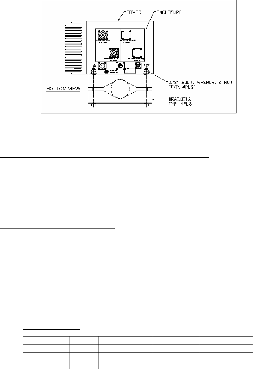
Diagram 1 – Side view of Cell Extender with Pole Mounting Brackets Installed
CONNECTING THE CELL EXTENDER TO THE BTS EQUIPMENT
The Cell Extender sits between the BTS equipment and the Antennas. The 7/16” DIN connector labeled
“FEEDER A (TX/RX)” is connected via a coax feeder line to the TX/RX output of the BTS. The
connector labeled “Antenna A (TX/RX)” is then connected to the actual Antenna. For BTS equipment
with receive diversity and Cell Extenders with Option 1 – Receive Diversity, the 7/16” DIN connector
labeled “FEEDER B (Rx only)” is connected to the “RX” input of the BTS equipment. Likewise, the
connector labeled “ANTENNA B (Rx only)” is then connected to the diversity Antenna.
POWERING THE CELL EXTENDER
The Cell Extender can be ordered with three separate power options: Direct AC (default), Remote
Power (Option 3), or Direct DC power (Option 5/6). With Direct AC, the Cell Extender is supplied with
a power cord that is plugged into a 110VAC or 220VAC power source. With the Remote Power option,
a remote power module (see Diagram 2) supplies the necessary voltage to the Cell Extender over the
coax cable. The Direct DC power option is for applications where a solar power source or battery
voltage is being used to power the unit. Two direct DC voltages are supported: 24-30VDC and 36-
72VDC.
With the Direct AC and Direct DC options, the Cell Extender is provided with a hermetically sealed
connector and a power cable that contains three wires – black, white and green. The pinouts are defined
below:
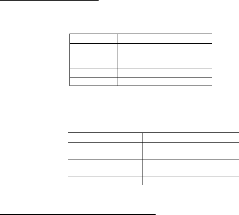
AC/DC Input cable
Wire Color Pin # Direct AC Direct 24VDC Direct 48VDC
Black PIN C Line (hot) No Connection No Connection
White PIN A Neutral +24-30 VDC +36-72VDC
Green PIN B Chassis Ground DC Return DC Return
100141-INST Cell Extender Model CE-1819-10G2 Page 3 of 5
Rev. - 05/2007 User Manual and Installation Instructions
CONNECTING THE ALARMS
The Cell Extender provides a dry relay contact for alarming purposes. Both the normally open and the
normally closed states are provided. A separate hermetically-sealed Alarm connector is provided with
wires as specified below:
Wire Color Pin # Function *
Black PIN D Common
White or
Yellow
PIN B Normally Closed
Red PIN A Normally Open
Green PIN C Not Used
* When unit is operational
The dry relay alarm is activated in the following conditions:
Alarm Trigger Conditions
LNA 1 Failure Loss of Gain > 3 dB
LNA 2 Failure Loss of Gain > 3 dB
PA 1 Failure Full Loss of Gain
PA 2 Failure Full Loss of Gain
Power Supply Failure DC voltage < +6VDC
SETTING UP THE BTS MAXIMUM TX POWER
The gain on the CE-1819-10G2 is fixed at the factory. No internal gain adjustments can be made in the
field. The user must verify that the composite input RF power to the Cell Extender does not exceed the
absolute maximum input level (+32.05dBm) in order for the RF output spectral emissions to be
compliant with the FCC spurious emissions limit of -13dBm outside of the assigned frequency block.
The maximum rated composite output RF power for this device is +43dBm.
This equipment complies with Part 24 of the FCC rules. Any changes or modifications not expressly
approved by the manufacturer could void the user’s authority to operate the equipment.
In order to comply with FCC rules for RF exposure, it must be observed that the antenna connected to
this equipment be fixed on an outdoor structure and that it must have a minimum separation distance of
3 meters between it and any person.
In accordance with RSS-131, the manufacturer’s rated output power for this equipment is for single
carrier operation. For situations when multiple carriers are present, the rating would have to be reduced
by 3.5dB, especially where the output signal is re-radiated and can cause interference to adjacent band
users. The power reduction is to be by means of input power or gain reduction and not by an attenuator
at the output of the device.
100141-INST Cell Extender Model CE-1819-10G2 Page 4 of 5
Rev. - 05/2007 User Manual and Installation Instructions
USING THE REMOTE POWER MODULE (Option 3)
The Remote Power Module allows the Cell Extender to be powered remotely over the coax line, thus
eliminating the need to run AC or alarm wires up the mounting structure to the unit. The Remote Power
Module is typically installed next to the BTS equipment and sits in-between the BTS and the Cell
Extender. With Option 3, the AC and ALARM connectors are no longer available on the Cell Extender,
but are now located on the Remote Power Module. The pinouts of these connectors remain the same. It
is also important NOT to mix the FEEDER A and FEEDER B lines (ie, make sure that the coax feeder
line hooked up to the FEEDER A connector on the Remote Power Module is ALSO hooked up to the
FEEDER A connector on the Cell Extender.
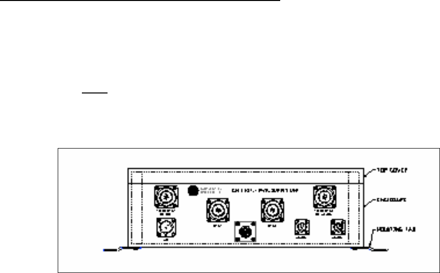
Diagram 2 – Remote Power Module (Option 3)
100141-INST Cell Extender Model CE-1819-10G2 Page 5 of 5
Rev. - 05/2007 User Manual and Installation Instructions
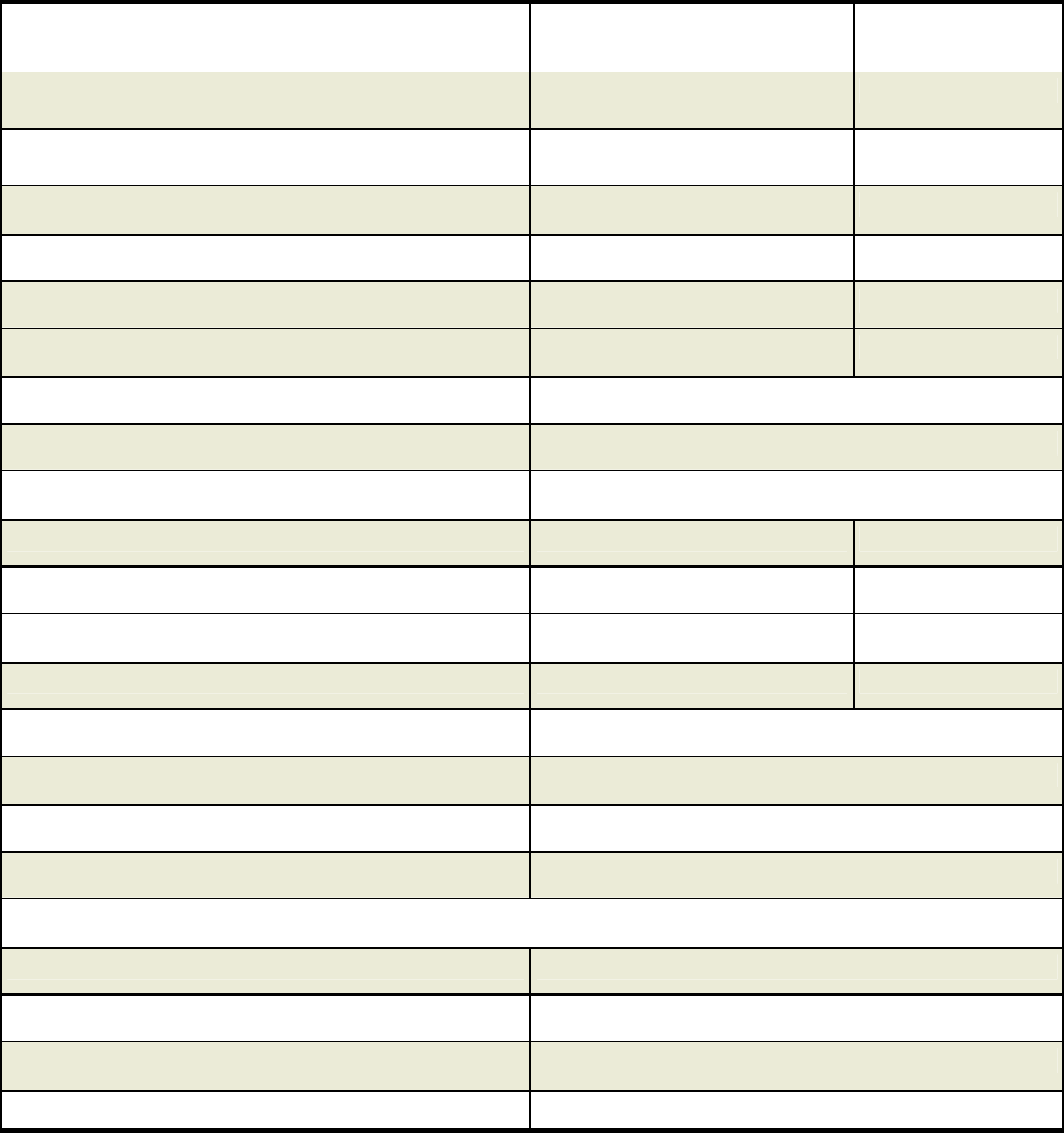
Cell Extender Electrical & Mechanical Specification
Uplink Downlink
A & D Blocks 1850-1870 MHz 1930-1950 MHz
B Block 1870-1885 MHz 1950-1965 MHz
C Block 1895-1910 MHz 1975-1990 MHz
E & F Blocks 1885-1895 MHz 1965-1975 MHz
System Gain 11dB max 10.95 dB max
20dB Nominal Bandwidth 56.65 MHz max 56.65 MHz max
System Noise Figure: 2.5 dB Max.
System Group Delay: 180 nanoseconds Max
Pass-band Ripple: 0.5 dB Max.
Output Third Order Intercept Point: +31 dBm Min. +62 dBm Min
1 dB Compression Point: +22 dBm Min. +52 dBm Min
Maximum Usable GSM/EDGE Power: N/A 20 Watts Composite
Input /Output VSWR: 1.5:1 Max. 1.5:1 Max.
Up-Link-Down-Link Isolation 80 dB
Number of Standard Inputs/Outputs: 1/1
Power Supply Voltage: 110/220 VAC
Current Consumption: 1.5/0.75 AMPS max at rated output power
Dimensions 13”L x 10 7/8”W x 7”H
Enclosure NEMA 4x Weather Proof
Connectors 7/16 DIN Type Female
Weight 20 Lbs. Max.
Mounting Pole and/or Wall Mountable