Communication Components CE-1819-20 Single Channel Amplifier User Manual USER GUIDE
Communication Components Inc Single Channel Amplifier USER GUIDE
USER GUIDE
Communication Components Inc
.
Communication Components Inc
.
Communication Components Inc
.
Communication Components Inc
.
Communication Components Inc
.
Communication Components Inc
.
Communication Components Inc
.
Communication Components Inc
.
Communication
Components Inc. 299 Forest Avenue Paramus, NJ 07652
TEL: 201-265-8882 FAX: 201-265-8922
Cell Extender for
Cell Extender forCell Extender for
Cell Extender for
Ericsson RBS 2301
Ericsson RBS 2301Ericsson RBS 2301
Ericsson RBS 2301
Micro Base Stations
Micro Base StationsMicro Base Stations
Micro Base Stations
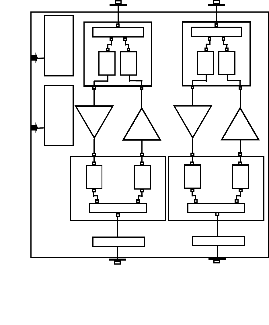
RBS 2301 Cell Extender
BLOCK DIAGRAM
Rx/Tx DUPLEXER
Rx
BPF Tx
BPF
Rx/Tx DUPLEXER
Rx
BPF
Tx
BPF
LNA
Monitor/
Alarm
(optional)
20 W
PA
Rx/Tx DUPLEXER
Rx
BPF Tx
BPF
Rx/Tx DUPLEXER
Rx
BPF
Tx
BPF
LNA
20 W
PA
Power
Supply
To Antenna
To RBS 2301
BIAS-T
(optional)
BIAS-T
(optional)
Communication Components Inc
.
Communication Components Inc
.
Communication Components Inc
.
Communication Components Inc
.
Communication Components Inc
.
Communication Components Inc
.
Communication Components Inc
.
Communication Components Inc
.
299 Forest Avenue Tel: 201 265-8882
Paramus, NJ 07652 Fax: 201 265-8922

CE-1819-20 Cell Extende
r
CE-1819-20 Cell ExtenderCE-1819-20 Cell Extende
r
CE-1819-20 Cell Extender
System Specification
System SpecificationSystem Specification
System Specification
General Information:
Communication Component Inc.’s Cell Extender products are designed to extend the range
and coverage area of Ericsson RBS 2301 Micro Base Stations in all GSM PCS applications.
The Cell Extender boosts the output power of the RBS 2301 to match the levels of
conventional Base Stations such as the RBS-2000 allowing for cost efficient implementation of
high capacity radio networks. It also provides low-noise amplification of the receive signal to
improve system sensitivity and to maintain a balanced link of the transmit and receive signals.
The Cell Extender is easy to install, requires no maintenance, and is fully compatible with
Ericsson Base Station equipment. The Cell Extender offers the maximum installation flexibility
by allowing the RBS2301 to be physically distanced from the antenna and mounting structure.
This overcomes the key key installation drawback of the RBS2301 which requires both a T1
connection and an AC connection on the mounting structure. Three installation options are
available:
• Configuration 1 - The CE-1819-20 can be mounted on the same mounting structure
directly underneath the Micro Base Station. This option is ideal when an existing
RBS2301 site is being upgraded with a Cell Extender or when both AC and T1
connections are available on the mounting structure.
• Configuration 2 - The RBS2301 is installed at ground level or indoors and the Cell
Extender is mounted on the mounting structure, in close proximity to the antenna. This
configuration is ideal for environments where AC lines and T1-connections are not
easily available on the mounting structure or when it is desired to keep the RBS2301
indoors. For this configuration, the Cell Extender should be ordered with the Remote
Power Option which includes a Bias-t and Remote Power Supply module to provide DC
power to the Cell Extender over the Coax cable.
• Configuration 3 - Both the RBS2301 and the Cell Extender are installed at the ground
level or indoors. This is intended for applications where it is impractical to install any
equipment other than the antenna on the mounting structure.
Communication Components Inc
.
Communication Components Inc
.
Communication Components Inc
.
Communication Components Inc
.
Communication Components Inc
.
Communication Components Inc
.
Communication Components Inc
.
Communication Components Inc
.
299 Forest Avenue Tel: 201 265-8882
Paramus, NJ 07652 Fax: 201 265-8922

Cell Extender System Specification
Description:
The Cell Extender is specifically designed for compatibility with the Ericsson RBS 2301
Base Station Equipment and is ensured to maintain the integrity of the GSM signal
amplification. This is achieved by utilizing state-of-the-art LDMOS technology for
amplification, monolithic Gallium-Arsenide technology low noise receive
particular emphasis on low system group delay to minimize Bit-Error-Rate (BER) of
transmissions.
The Cell Extender block consists of a single compact unit with four RF connectors
single AC line for power. It is housed in a moisture proof NEMA 4X aluminum
enclosure with integrated heat sinks and is suitable for either outdoor or indoor
The Cell Extender is designed to boost both low power tranceivers (both cells)
provided with RBS 2301. It contains redundant low noise amplifiers to boost the
signals, redundant LDMOS-based high power amplifiers to boost the transmit signal,
duplexers, an integrated power supply and alarm/control circuitry to monitor the
the unit. The Cell Extender is powered by a conventional 110/220 VAC source or
optionally DC-powered via the Coax cable using Remote Power
O
.
Ordering Options:
Model CE-1819-20 01: Single Channel
02: Monitoring
03: Remote Power Option (with internal
A
D: A & D Block Operation
B: B Block Operation
C: C Block Operation
Communication Component
s
Communication Component
s
Communication Component
s
Communication Component
s
Communication Component
s
Communication Component
s
Communication Component
s
Communication Component
s
299 Forest Ave. Tel: 201 265-8882
Paramus,NJ 07652 Fax:201 265-8922

Cell Extender System Specification
Electrical Specification Up-Lin
k
Down-Lin
k
•Model CE-1819-20 A&D Block: 1850-1870 MHz 1930-1950MHz
• Model CE-1819-20 B Block: 1870-1885 MHz 1950-1965MHz
• Model CE-1819-20 C Block: 1895-1910 MHz 1975-1990MHz
• Downlink:
• System Gain 10 dB
• Gain Flatness ± 0.5 dB Max
• Output 20 Watts Min
• 1 dB Compression 15 Watts Min
• Input/Output 1.5:1 Max
• Up-link 90 dB Min
• Uplink:
• System Gain 10 dB
• Gain Flatness ± 0.5 dB Max
• Noise Figure: 2.5 dB Max.
• Output Third Order Intercept +31 dBm Min.
• Input/Output 1.5:1 Max
• Down-link 90 dB Min
• Operating 115/220VAC or 28VDC
• Current 1.3 A @
Mechanical Specifications
•Dimensions: 17”x 9”x 7”
• Enclosure: NEMA 4X Aluminum Die-cast
• Connectors: 2 N Type female to RBS
2 7/16 DIN to Antenna
• Weight: 20 Lbs. Max.
• Mounting: Mounting Studs
Communication Component
s
Communication Component
s
Communication Component
s
Communication Component
s
Communication Component
s
Communication Component
s
Communication Component
s
Communication Component
s
299 Forest Avenue Tel: 201 265-8882
Paramus, NJ 07652 Fax: 201 265-8922
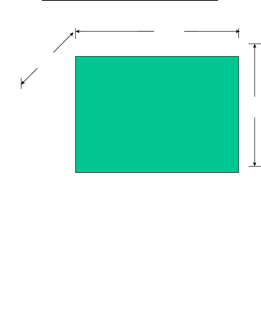
Cell Extender Model CE-1819-20
9”
17”
7”
Photo of Cell Extender
Model CE-1819-20B
Communication Components Inc
.
Communication Components Inc
.
Communication Components Inc
.
Communication Components Inc
.
Communication Components Inc
.
Communication Components Inc
.
Communication Components Inc
.
Communication Components Inc
.
299 Forest Avenue Tel: 201 265-8882
Paramus, NJ 07652 Fax: 201 265-8922