Communication Components DAB-DAC-1819-2 GSM Amplifier User Manual Professional Letter
Communication Components Inc GSM Amplifier Professional Letter
users manual

COMMUNICATION
COMPONENTS INC 89 Leuning Street Phone: 201-342-3338
2nd Floor Fax: 201-342-3339
South Hackensack, NJ 07606 www.cciproducts.com
Extending Wireless Coverage
GSM Dual Amplifier Booster/ Combiner
CCI Model Number DAB-1819 & DAC-1819
With
Nortel S8000 GSM Base Transceiver Station
USER’S GUIDE
Product Description:
DAB-1819 & DAC-1819 Dual Amplifier Booster/ Combiner:
The CCI GSM Dual Amplifier-Booster Module (DAB) consists of two linear power
amplifiers with intermodulation level control circuitry. The Dual Amplifier-Combiner
Module (DAC) is identical to the DAB Module with the exception of a passive hybrid
combiner at the output which combines both signals to provide two 30-35 Watt GSM
signals on a common output.
Nortel S8000 GSM Base Transceiver Station:
The Base Transceiver Station (BTS) is a GSM Base Station which serves one cell
and is controlled by the Base Station Controller (BSC). The S8000 is available in an
outdoor and indoor versions of the BTS respectively. The BTS contains the radio
transceivers and all the digital signal processing equipment. The BTS contains eight
DRX/Power Amplifiers for a total of eight transceivers per BTS. The trancievers
operate in the frequency band of 1930 to 1990 MHz. There are 299 channels
available with a channel spacing of 200 KHz. The transmitter is a constant envelope
using 0.3 GMSK modulation, which is MSK filtered with a Gaussian filter, having a
BT product of 0.3. The transmitter is capable of operating in a Time Division Multiple
Access (TDMA) system. For each channel there are 8 time slots available, each
containing digital speech or data.
Operation Description:
The DAC-1819 and DAB-1819 Dual Amplifier Booster/ Combiner in conjunction with
the S8000 BTS are designed to supply a nominal output power level of 47.5 dBm
when used in the uncombined mode and 44.5 dBm when used in the combined
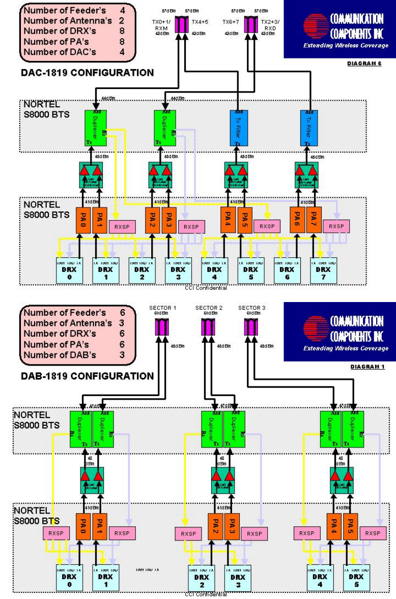
mode at the antenna connector. A system block diagram is shown on diagram #1
and #2..
z Page 2

z Page 3
Although the gain of the Dual Amplifier Booster/ Combiner is fixed, the output can be
adjusted by setting the input power level. The input to the Dual Amplifier Booster/
Combiner is the Nortel Power Amplifier (PA) whose output can be set at 16 power
levels in 2dB increments. As shown in diagram #1 and #2, setting the output level of
the PA to 41 dBm will result in a power level at the output of the Dual Amplifier
Booster/ Combiner of 45.5 dBm in the combined mode.
The Dual Amplifier Booster/ Combiner is followed by a Duplexer or TX filter module
which contains both a low-pass filter and duplex filter. The low-pass filter secures the
required reverse isolation and provides spurious and harmonic suppression of the
output signal. The duplex filter allows a single antenna to be used for both
transmitting and receiving. Due to the insertion loss of the Duplexer, the maximum
output power at the antenna connector of the radio base station is 44.5 dBm in the
combined mode.
Operation and Installation Instructions:
The following instructions should be followed when installing the unit in service:
• Apply a 26-28VDC input voltage to the DC Input connector of the Dual
Amplifier-Booster/Combiner Module.
• Insure that the DC Source is capable of delivering up to 15 Amps at 28VDC.
• Apply a GSM signal of up to +41dBm to each RF input port of the Dual
Amplifier-Booster/Combiner Module.
• The Dual Amplifier-Booster/Combiner Module will provide approximately
7.5dB or less of RF Gain.
• Check the RF output to insure the proper output power is present.
{Approximately 30-35 Watts in the combined mode (DAC)}.
• Adjust the input power level to insure the output power level is in compliance
with the values indicated in the table on page 2.
• Install the Alarm Connector to the Alarm Output connector of the Dual
Amplifier-Booster/Combiner Module.

z Page 4
Setting the RF Output Power on the DAB & DAC Booster Amplifier
The RF output power is not adjustable on the DAB & DAC Booster Amplifier. The
user must adjust the RF input power to the Booster Amplifier such that the RF output
power level does not exceed the levels shown below in order for the RF output
spectral emissions to be compliant with the FCC spurious emissions limit of -13 dBm
outside of the assigned frequency block. These levels must not be exceeded.
Channel Center
Frequency (MHz)
Maximum RF 0utput
(Watt)*
1930.2-1989.8 35 (combined mode)
This equipment complies with Part 24 of the FCC rules.
In order to comply with FCC rules for RF exposure, it must be observed that “the
antenna connected to this equipment be fixed on an outdoor structure and that it
must have a minimum separation distance of 2 meters between it and any
person."