Comotech ALME1000 60 GHz Transceiver User Manual Eng 0 Front Cover Index
Comotech Corporation 60 GHz Transceiver Eng 0 Front Cover Index
Comotech >
User Manual
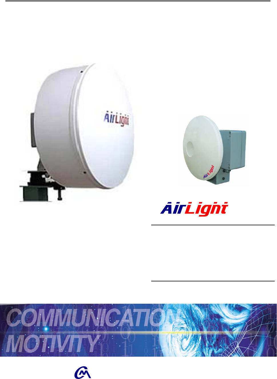
Millimeter-wave Radio Communication System
Installation and Service Manual
TM
60 Series - ME1000/100
70 Series - TE1000/100
COMOTECH CORPORATION

TM
60 Series – ME1000 / ME100
70 Series – TE1000 / TE100
Copyright ©2004 Comotech Corp. All Rights Reserved.
Comotech Corp. has an exclusive right to the information included in this
document, and this matter is protected by the related copyright, patent, and
intellectual property right. The products and software stated in this document
can’t be translated into another language by arbitrary forms or ways without the
written consent of Comotech Corp. and can’t be kept, photocopied, delivered, or
reorganized into storage media. Comotech products are explained in this
document to simply provide the information. It doesn’t guarantee the matters
indicate or include the future performance improvement. The Comotech product
design and performance can be changed without prior notice or consent. The
registered unique marks and trademark rights such as the products and
company names indicated in this document are owned by individual companies
and used for verification or explanation not to damage the owner’s profit.

1. Introduction
1-1. AirLight™ Family …….……………………………………… 1-1
1-2. Advantages of AirLight™ Series …….……………………………………… 1-1
1-3. AirLight™ Features …….……………………………………… 1-2
1-4. AirLight™ Application …….……………………………………… 1-3
2. Description
2-1. General Equipment …….……………………………………… 2-1
3. Deployment
3-1. Pre-Installation Notice …….……………………………………… 3-1
3-2. Installed-Location Notice …….……………………………………… 3-2
3-3. Safety and Notice …….……………………………………… 3-3
3-4. Tools and Equipments …….……………………………………… 3-5
3-5. How to Connect AirLight™ …….……………………………………… 3-6
3-6. Cabling Check …….……………………………………… 3-12
4. AirLight™ Monitoring Program(ALMP)
4-1. Introduction …….……………………………………… 4-1
4-2. Installation …….……………………………………… 4-2
4-3. Getting Start …….……………………………………… 4-3
5. Troubleshooting
5-1. General ALMP Features …….……………………………………… 5-1
5-2. Problem Solving …….……………………………………… 5-1
6. Specification
6-1. AirLight 60 Series Specification …….……………………………………… 6-1
6-2. AirLight 70 Series Specification …….……………………………………… 6-2
7. Terminal Location …….……………………………………… 7-1
8. Warranty …….……………………………………… 8-1
★ Table of Contents ★
1 - 1
Introduction
1. Introduction
1-1. AirLight™ Family
AirLight™ applies the original Comotech technology to millimeter-wave and
provides the system doing the wireless transmission of various types of
digital signals from 100 Mbps to 1.25Gbps. Especially, Fast Ethernet (125
Mbps) and Gigabit Ethernet (1.25Gbps) are provided with standards, and
product flexibility is provided to determine the desired standards depending
on user requirements.
1-2. Advantages of AirLight™ Series
√ High Tech – Application of original Comotech technology has further
enhanced the reliability of millimeter wave band products.
√ Unlicensed Frequency Band – There are many countries that generally
don’t need license and declare to use the frequency in case of 60 series.
√ High Data Transmission Speed – The systems with various speeds from
100 Mbps to 1.25Gbps can be serviced and supported.
√ High Security and Frequency Reuse – Good security is guaranteed by
high directivity, and the reuse of frequency in the unit of pico cell is
possible due to the frequency characteristics of the millimeter wave.
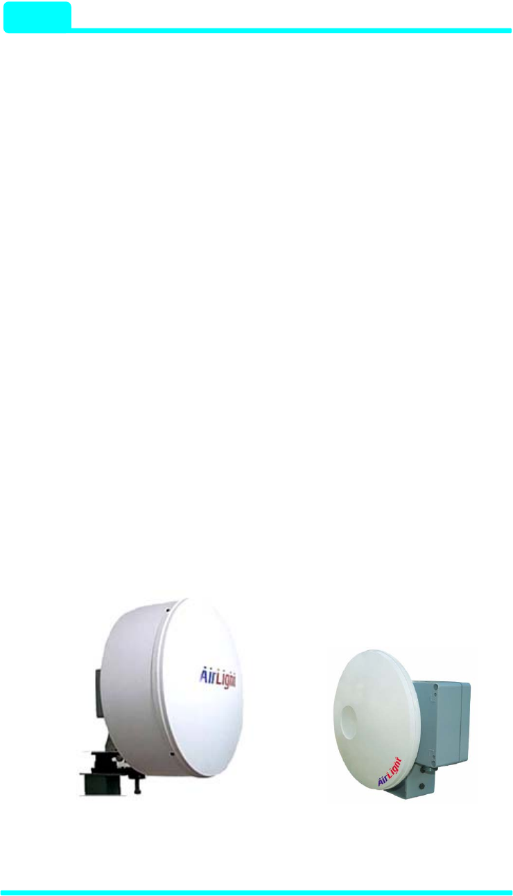
TE1000C-24/ME1000C-24 TE1000C-12/ME1000C-12
TE100C-24/ME100C-24 TE100C-12/ME10C-12
Figure 1-1 AirLight™ ODU (Out Door Unit)

Introduction
- 60 / 70 Series 1 - 2
1-3. AirLight™ Features
AirLight™ has the following features.
▶ Next Generation Communication Technology
√ Integration of high tech
√ Digital direct conversion
√ Good security
√ Data acceptance capability with high capacity
√ Low power consumption
▶ Wireless and Fiber Distributed Network Configuration
√ Use of the unlicensed frequency in the 60GHz band – ME100 /
ME1000
√ Possible to connect to the system using binary digital signals
√ Support of the maximum 1.25Gbps (Gigabit Ethernet) speed from
100 Mbps
√ Support of various interfaces: FDDI, UTP, etc.
√ Possible to design in compliance with the communication regulation
of each country ( FCC, TELEC, ITU-R)
▶ Low Cost and High Efficiency
√ Possible to configure very high speed network with the low cost
√ Low maintenance and repair cost without laying
√ Possible to install and operate with the small number of persons (1
or 2 persons)
√ Possible to send the data with high capacity and flexibly connect to
another system
√ Possible to connect to IP network
√ The same transmission efficiency as the wired one
COMOTECH CORPORATION

1 - 3
Introduction
▶ Efficient Network Management
√ Provision of the efficient network management program (IDU)
√ Support of the RS-485 communication port to check the AirLight™
state
√ The management function by ALMP, AirLight™ Monitoring Program
1-4. AirLight™ Application
AirLight™ is a ultra high speed wireless LAN communication product.
Configuring the wireless network with P2P, P2M, or M2P types among large
buildings makes it possible to communicate the data with the adjacent
system through the wireless network. This configuration can replace the
area difficult to lay the optical cables and communication facilities requiring
high security. The wired and wireless double security management system,
Using both network among banks in the neighborhood, and the regional
administration network can be immediately configured. When LAN is
configured in the area where buildings such as schools are stand close
together, capability expansion is needed, or the current communication
network is to be repaired, use it for a temporary installment to provide the
stable communication service.
-- Low Cost for Maintenance and Repair --
AirLight™ can be installed by only a few workers one or two. The
maintenance cost during line operation is extremely low compared to the
optical cable, so there is an economical aspect of saving the cost.
Furthermore, when the construction of the optical communication network in
communication service isn’t provided due to the man-made or natural
disaster, the service can be seamlessly provided using AirLight™ during
the recovery of the optical communication network.

Introduction
- 60 / 70 Series 1 - 4
-- Large Capability of Data Transmission --
The current communication market requires more data transmission
capability. The network configuration between cities can be achieved by
laying the optical cable, but laying the optical cable in the city requires a lot
of cost and time.
Using AirLight™, there all the problems can be solved in the place that
needs LAN communication with large capacity of transmission in the
downtown area.
-- Easy to Expand the Capacity --
When the additional lines are needed due to the increase of subscribers in
the specific area or data processing capacity needs to be expanded, setting
up AirLight™ can make the communication service quality improved and
the capacity expanded.
COMOTECH CORPORATION
1 - 5
Introduction
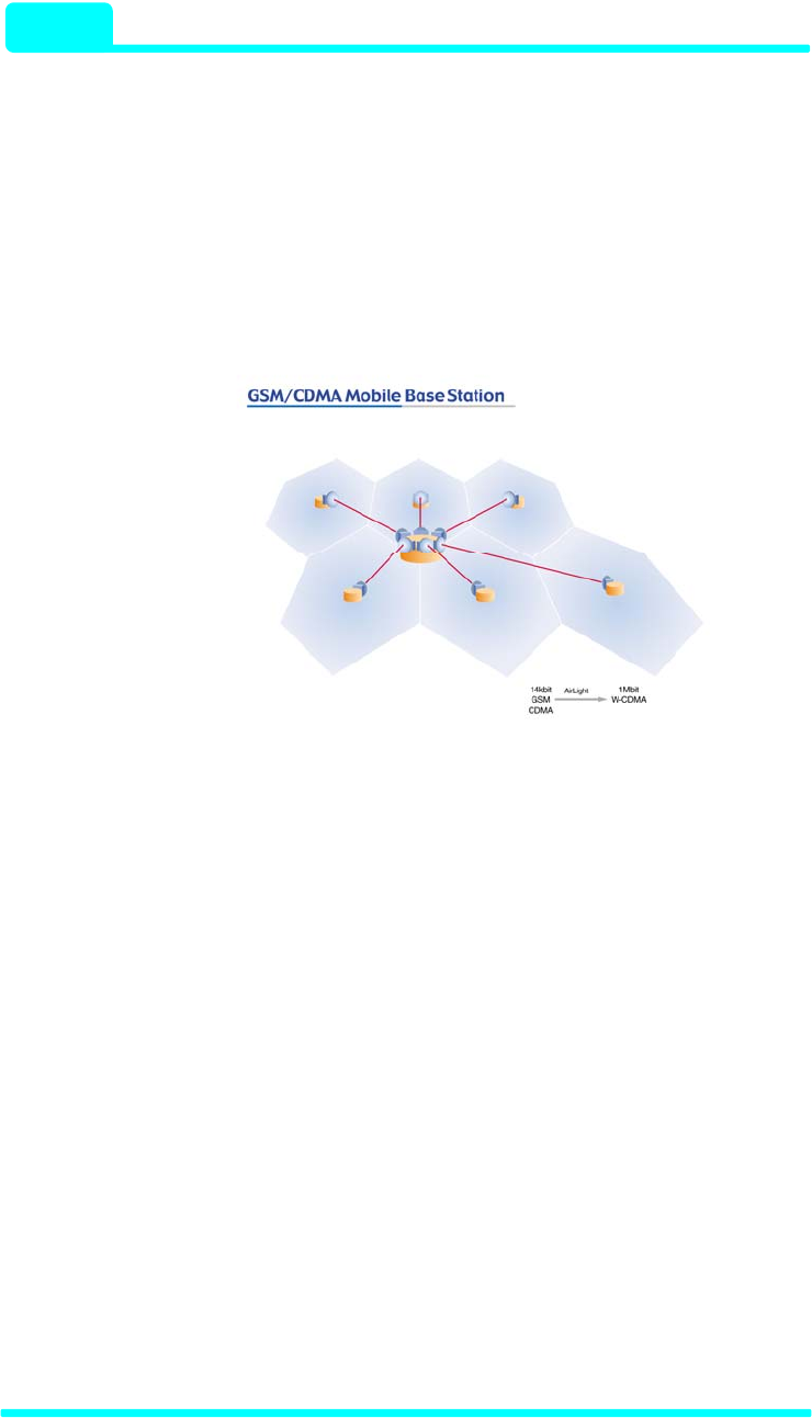
▶ GSM/CDMA Mobile Base Station
When GSM (14 kbps) doing the low speed data communication in the
mobile environment is converted into W-CDMA (1 Mbps) making the
multimedia service possible, the large data transmission between repeater
station can be serviced with AirLight™. Moreover, it is possible to process
the large amount of data required due to the increase of subscribers.
Figure 1-2 GSM/CDMA Mobile Base Station
Introduction
- 60 / 70 Series 1 - 6
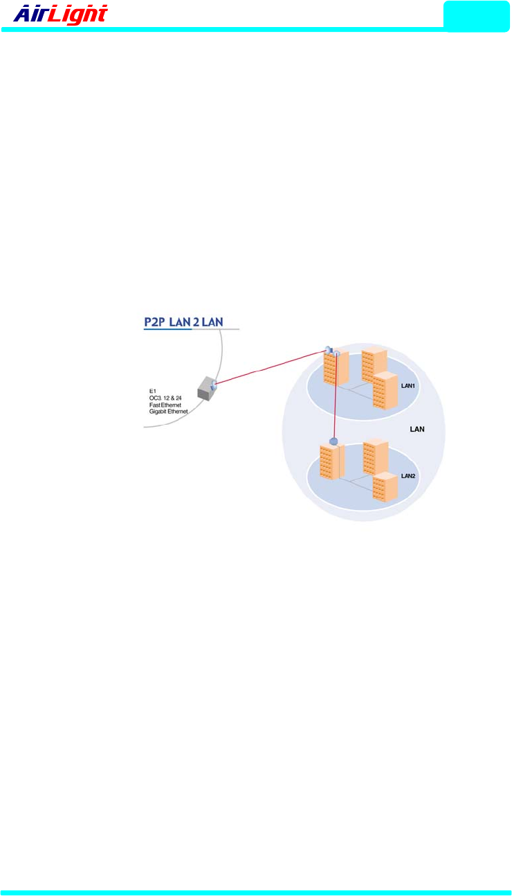
▶ P2P LAN Link
If several groups of LANs need to be connected, the installation is possible
by using AirLight™ more quickly and cheaply than the optical cable.
Moreover, the large amount of data comparable to the optical cable speed
can be transmitted, and it has an advantage of easy installation and
operation. In case of removing the service network, it is possible to reuse
the product. Furthermore, in case of expanding lines due to the increase of
subscribers, it is extremely easy to replace it with a high-end product.
Figure 1-3 P2P LAN2LAN
COMOTECH CORPORATION
1 - 7
Introduction
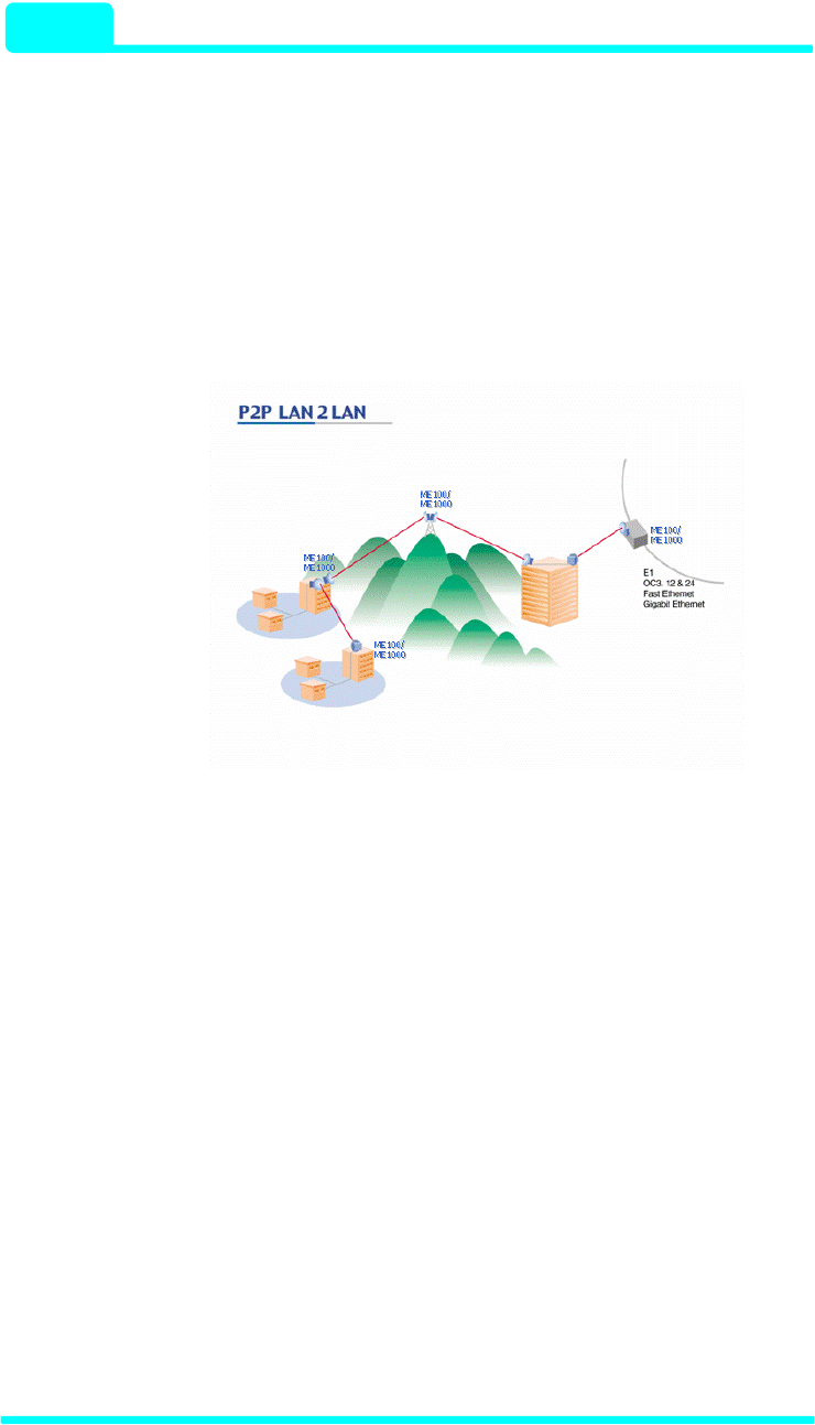
▶ Point-to-Point Wireless Link
In case of providing the communication service across rivers or mountains,
the optical line configuration work doesn’t come up to AirLight™ in terms of
cost and practical use. It is simple and easy to set up AirLight™. In case of
expanding lines, it can be replaced with a broadband capacity AirLight™
product or an additional installation can be set up for service.
Figure 1-4 Point-to-Point Wireless Link
Introduction
- 60 / 70 Series 1 - 8
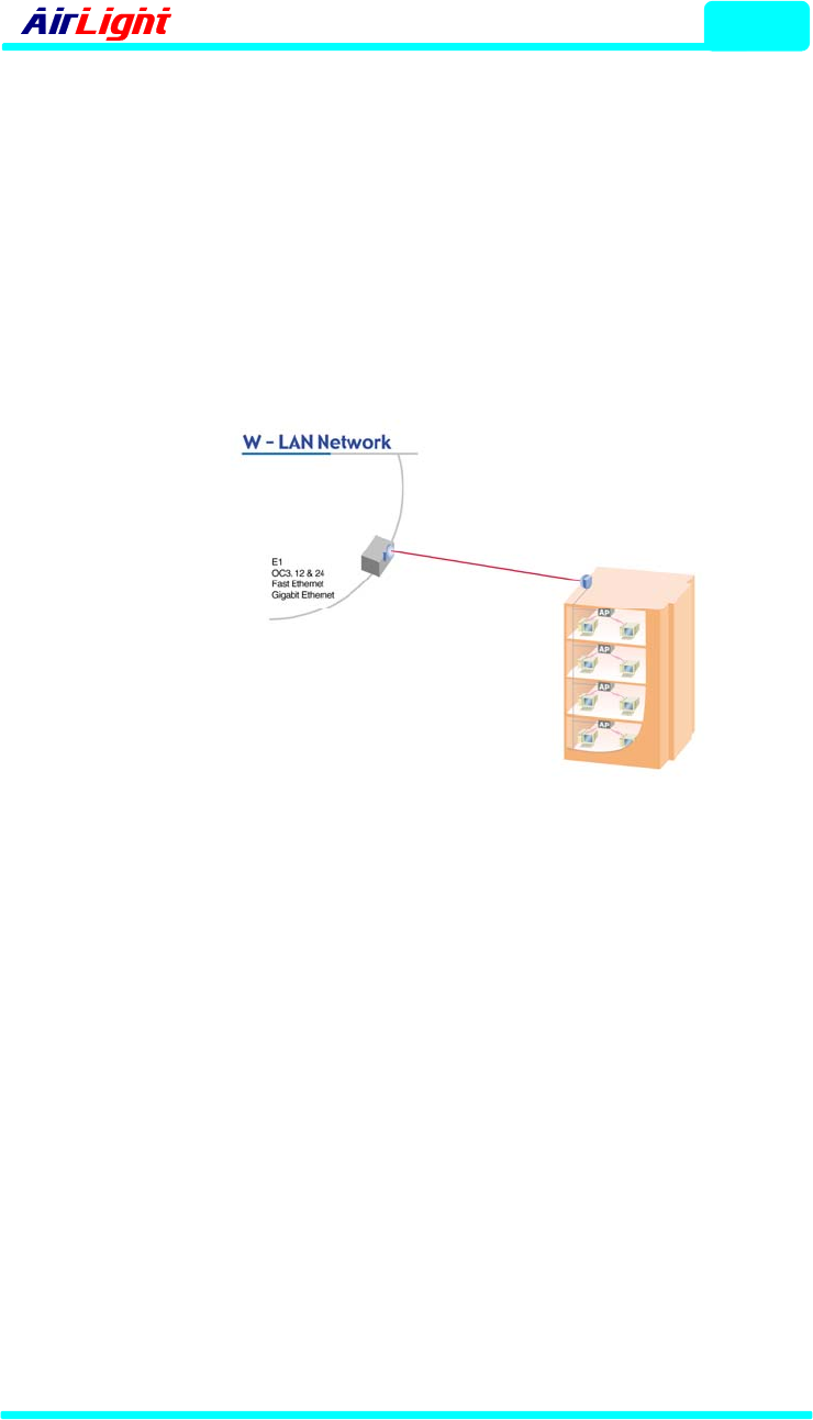
▶ W-LAN Network
When installing the wireless LAN to be used in the downtown, many
wireless LAN access points can be grouped for transmission to the adjacent
network using AirLight™. AirLight™ guarantees high compatibility and
large data transmission. It is the optimal solution to minimize the installation
and incidental expenses occurring due to the increase of the data usage in
the downtown.
Figure 1-5 W-LAN Network
COMOTECH CORPORATION
1 - 9
Introduction
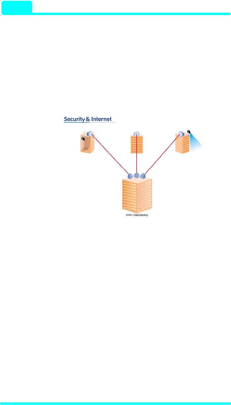
▶ Security & Internet
In case of implementing the centralized management by grouping CCTV
security systems in a company, a new transmission line is needed.
AirLight™ can handle all of these matters. In case of using the current
wired network and the wireless network with AirLight™, the stability of the
security system can be enhanced.
Figure 1-6 Security & Internet
Description
2 - 1
2. Description
AirLight™ consists of a wireless transmitter and receiver, management
software(ALMP) and a manual. The wireless transmission and receipt
device is physically composed of RF main unit, optic to electrical converter,
power supply unit and system protection case with antenna and alignment
bracket.
2-1. General Equipment
Main parts of AirLight™ are basically as follow.
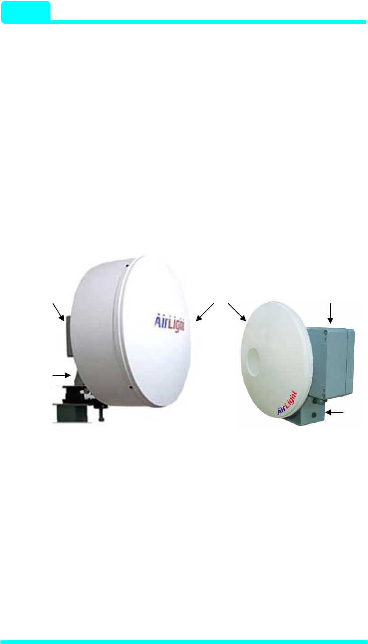
Antenna System Body
System Body
Alignment
Bracket
Alignment
Bracket
TE1000C-24/ME1000C-24 TE1000C-12/ME1000C-12
TE100C-24/ME100C-24 TE100C-12/ME10C-12
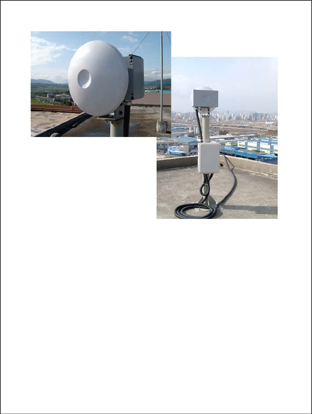
Figure 2-1 AirLight™ Part-Name
▶Antenna
Antenna is directly related to the transmission distance of AirLight™. The
Fig. 2-1 shows the 24 inch and 12 inch Cassegrain parabolic antenna.
Various sizes of antennas are available to provide the optimal solution
depending on user needs.
▶System Body
It is the part the wireless communication system is mounted to. To support
Description
- 60 / 70 Series
2 - 2
stable performance from severe weather can didn’t such as and heat
radiation, an excellent aluminum case is used and the external surface is
coated with powder to protect from corrosion.
▶Alignment Bracket
The antenna provided by AirLight™ has usually narrow beam width,
because of the high frequency range of millimeter-wave of 60GHz or 70GHz.
Alignment bracket makes the installation easy doing deployment. It can be
tilted within 10 degrees upward and downward and 10 degrees left and right.
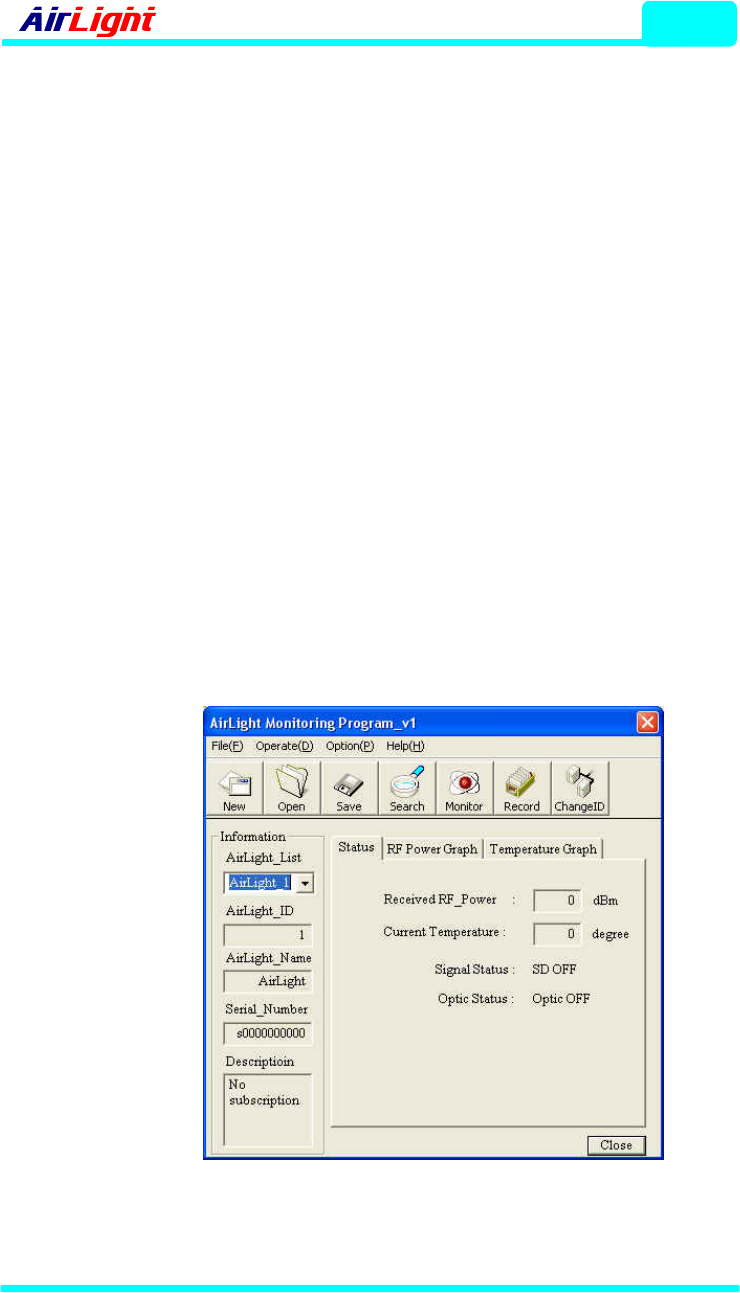
▶ALMP (AirLight™ Monitoring Program)
The program checking the operation status of AirLight™ is provided. With
the internal functions of the program, the AirLight™ states such as the
receipt status of RF signals, the connection state of internal transmission
signals, internal temperature, etc. can be recorded and checked. Currently, it
supports IBM-compatible OS and Windows OS, and UNIX, Linux, and Mac
OS will also be supported depending on customer requirements.
Figure 2-2 ALMP Main Window
COMOTECH CORPORATION

Installation
3 - 1
3. Deployment
3-1. Pre-Installation Notice
Workers installing AirLight™ should check the following before installing it.
√ Is the space for installment sufficient and are there any dangerous
facilities nearby?
- The location should be selected to safely install and maintain and
suitably manage it.
√ Are things and tools needed for installment secured?
(Refer to section 3-4.)
- Thoroughly prepare the things needed for fast installation.
√ Is the structure (ex. mast) suitable to fix the equipment available?
(Refer to section 3-5.)
- It should be possible to firmly fix it to get the best communication
quality.
WARNING
Workers installing the equipment should check the above
matters before installation to prevent the accident that may
occur during installation.

Installation
- 60 / 70 Series
3 - 2
3-2. Install-Location Notice
The following matters should be considered to install AirLight™.
√ Line of Sight
As for the installation conditions of AirLight, buildings, pylons, or trees
should not be in the line of sight from another AirLight, and it should be
installed fairly high enough from the floor.
√ Mast
The mast for AirLight installation must be stably fixed not to be vibrated by
gales or rain. Vibration may degrade communication quality.
√ Permission
Installation location should be approved by the building owner or
superintendent. Installation methods and other matters meet local
requirements.
COMOTECH CORPORATION

Installation
3 - 3
3-3. Safety and Notice
AirLight™ is designed to sand against severe environment, but the
following matters should be attended to use it safely for a long time.
Installation▶
√ Putting inflammable materials beside the product may cause a fire.
√ Installing it in the unstable or vibrating place or in the place right
ahead of the wall may degrade communication quality.
√ Dropping it or putting a lot of impact on it may cause the product
break down, so be careful to handle it.
√ Even though this product is dropped down, it shouldn’t contact the
electric wire. It is good to take a necessary safety action during
installation.
√ If the product isn’t installed according to the operating instructions, it
may impede wireless communication.
√ Installation and repair need technicality and experience, so the after
sales service center or sales store can safely handle it at user
request. There is no part a user can fix inside, so if arbitrarily
disassembled, it may cause a breakdown or degrade communication
quality.
▶Power
√ The power terminal should be securely fixed not to be vibrated. If the
connection is unstable, it may cause a fire.
√ Don’t put heavy things on the power cord, or don’t let the cord
pressed under the device so that it shouldn’t be damaged. Otherwise
it may cause an electric shock and a fire.
√ Don’t let the water inside through the power cord protection tube to
avoid the electric shock accident.
√ Be careful that putting the power cord beside the heating device may
have the coating of the cord melted down.
√ The working voltage must be checked before using the product.

Installation
- 60 / 70 Series
3 - 4
Wrong or not connect power source and voltage cause a failure.
▶Caution
√ This product consists of precise parts, so any disassembling or
remodeling the product by user may cause a fatal breakdown. If a
failure occurs because of it, the manufacturer isn’t responsible for
product quality.
√ If the antenna is covered with a lot of filth, get it off with the smooth
cloth stained with the neutral detergent and rub. Then, rub it off
again with the clean cloth. Using chemicals such as organic solvents,
alcohol, and benzene may damage the product. Never use them.
√ Don’t use it in the state of failure such as no communication.
Immediately turning off the power switch and separating the power
source, contact the after sales service center or sales store for safe
handling.
√ Turning off the power source reduces the risk of an electric leakage
or a fire, when the product isn’t used for a long time.
COMOTECH CORPORATION

Installation
3 - 5
3-4. Tools and Equipments
The following tools and equipments are needed to install AirLight™. Workers
installing the device should check the following things.
▶Things Needed for Installment
√ Power cables --- AC: FG, AC(N), AC(L), DC: +V, -V
√ Cables for administration --- RS-485 twist cables (AWG24)
√ Optic cables for communication --- SC type, multimode optic cables
√ Flexible tubes (22mm diameter)
√ Other tools
▶Things Needed for Checking the Communication State
(Do not provide)
√ Laptop Computer --- Using the ALMP program
- RAM: 128 Mbytes
- Hard Disk: 20Mbytes
- OS : Microsoft® Window 2000® or XP
- Video Resolution: 1024 X 768
- Interface: Serial COM port
√ RS232 to RS485 converter
√ Cables needed for other connections
Installation
- 60 / 70 Series
3 - 6
3-5. How to Connect AirLight™
Fully understand the following matters before setting up AirLight™ and
install it.
WARNING
AirLight™ uses two types of models using AC 100 ~ 240V
(50/60Hz) or DC (+/-) 48V as the input power source. Before
connecting it to the power source, be sure to check if the
purchased product operates with AC or DC.
3-5-1. Connection Terminals of AirLight™
1. The Power Input Terminals
There are power input terminals for AC and DC. The one for AC
connects it to the 100 ~ 240V (50/60Hz) power source. The one for DC
connects it to the (+) 48V or (-) 48V power source.
Note : When the power source is connected properly in AirLight™,
PWR LED is turned on.
2. Communication Terminals (Optical)
The terminal connecting it to the external network uses the optic cable.
The multimode SC type connector is default, Wavelengths of ME100
and TE100 are both 1310nm, and those of ME1000 and TE1000 are
both 850nm.
Note : There is OSD LED in AirLight™. If AirLight™ is correctly
connected to the network equipment, it is turned on.
3. Management Terminals (RS-485)
After installation or completion, various types of information can be
obtained through this communication terminals. (Refer to chapter 4
ALMP.)
COMOTECH CORPORATION
Installation
3 - 7
3-5-2. Connecting the AC Power Source
There are 3 terminal blocks to connect the power source inside AirLight™.
The connection is fastened with M3 bolts.
As for the electric wire coming from the outside, use the wire with the
diameter of 0.75mm or larger to stably supply the electricity.
It is recommended to use the ring type tinned copper terminal end or PVC
insulated type tinned copper terminal end to connect the terminal block and
the wire. The internal diameter of the solderless terminal should be 3.2mm.
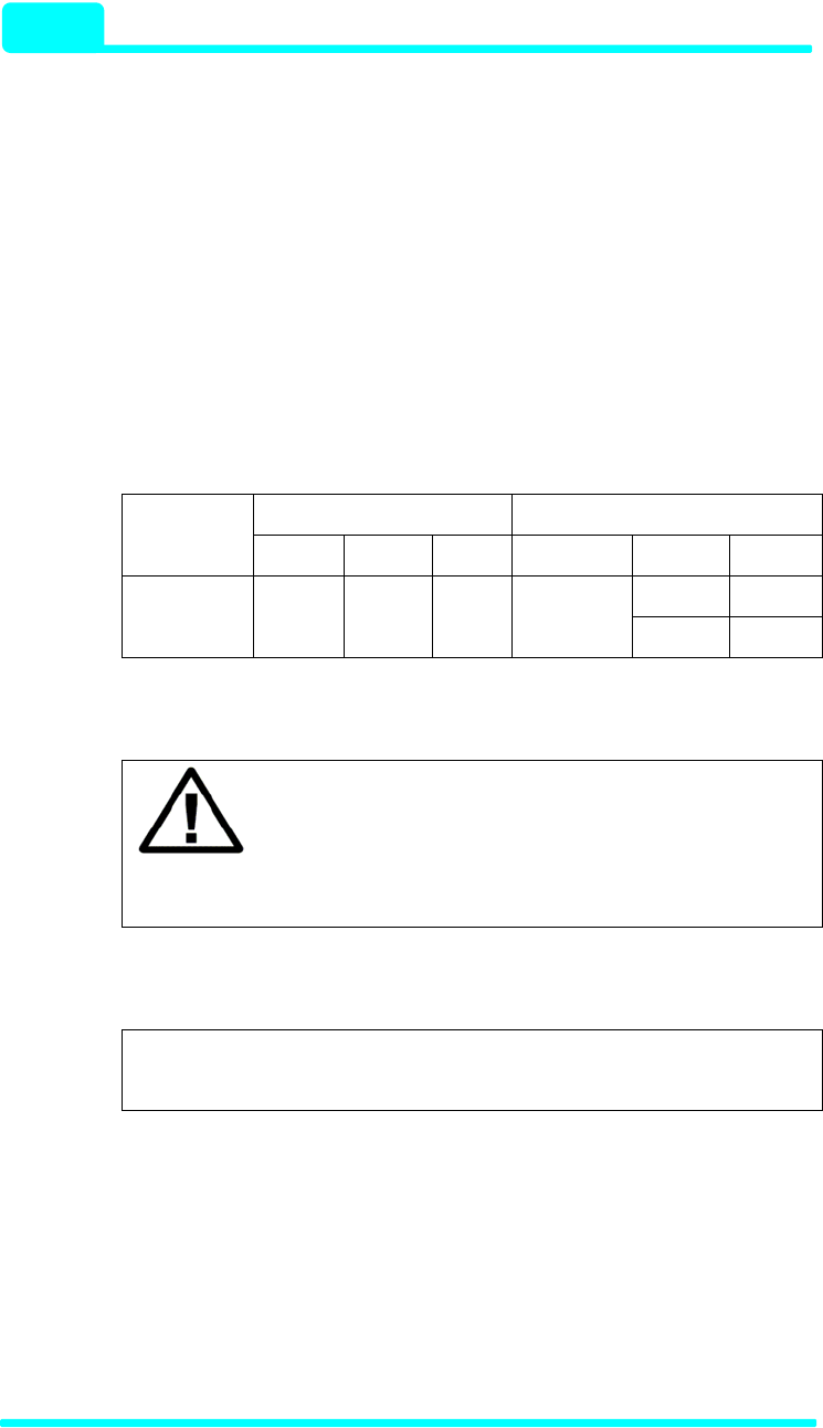
Table 3-1 Terminal Blocks Connecting the Power Source
AC DC
Terminal FG AC(L) AC(N) NC (+)V (-)V
Ground -48V Input
Voltage Ground AC100
~ 240V 0V Not
Connected +48V Ground
WARNING
There are two types (AC or DC) of power sources for
AirLight™. Check if the purchased product operates
with AC or DC.
Note : As for the location of the AirLight™ power source
terminal, refer to Chapter 7.
Installation
- 60 / 70 Series
3 - 8
3-5-3. Communication Terminals (Signal I/O Ports)
AirLight™ basically supports optic terminals. The following table 3-2 shows
the specification of standard optic terminals. Contact Technical Support
Team of Comotech to use the customer’s previous network and change the
interface.
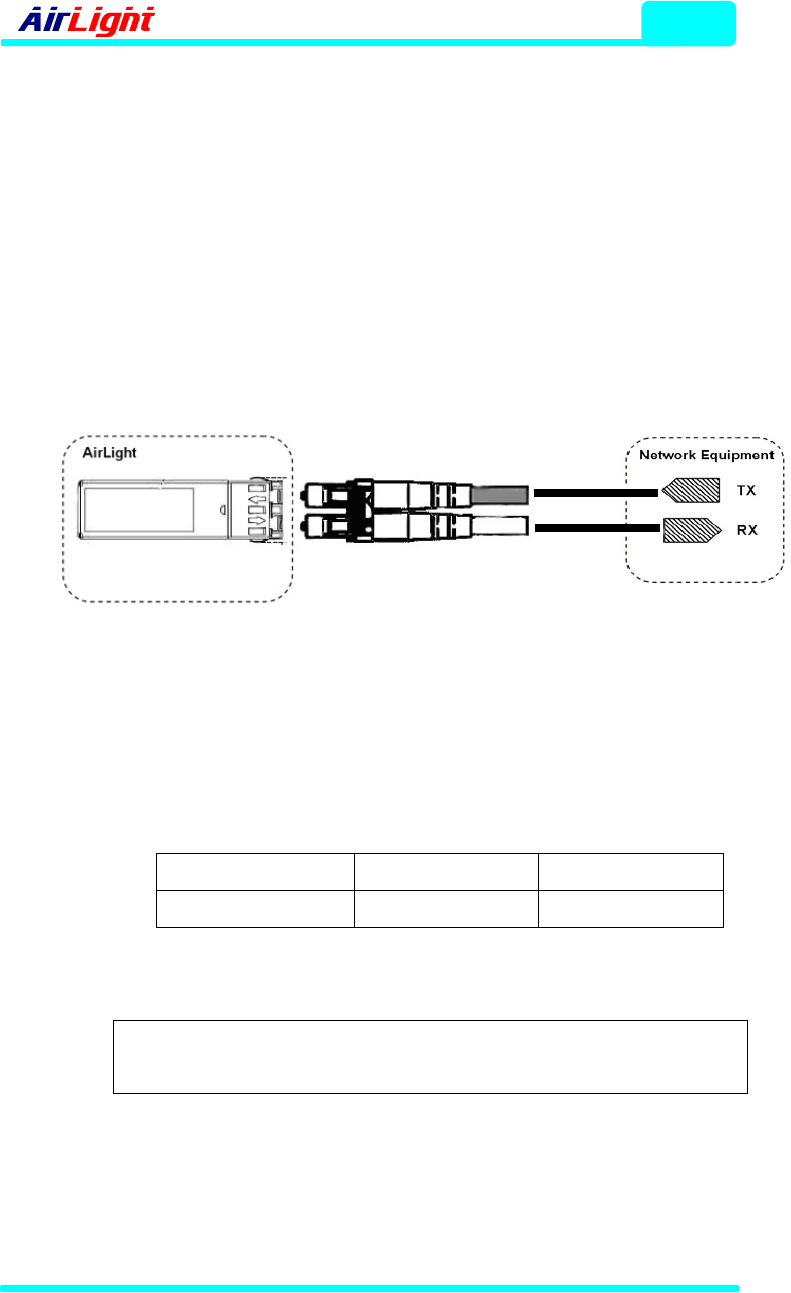
The communication terminals of AirLight™ are connected as shown in Fig.
3-1. The RX terminal of AirLight is connected to TX of the network
equipment, and the TX terminal is connected to RX.
Figure 3-1 Network Connection
The optic fiber type of AirLight™ is shown in Table 3-2. Connecting to
network equipments, refer to the standards of Table 3-2.
Table 3-2 Optic Fiber Type
Model Type ME100 / TE100 ME1000 / TE1000
I/O Terminal 1310nm / MM / LC 850nm / MM / LC
Note : As for the location of the AirLight™ communication terminal,
refer to Chapter 7.
COMOTECH CORPORATION
Installation
3 - 9
3-5-4. Management Terminals (RS-485 Terminals)
RS-485 is the function provided to check the operation state of AirLight™.
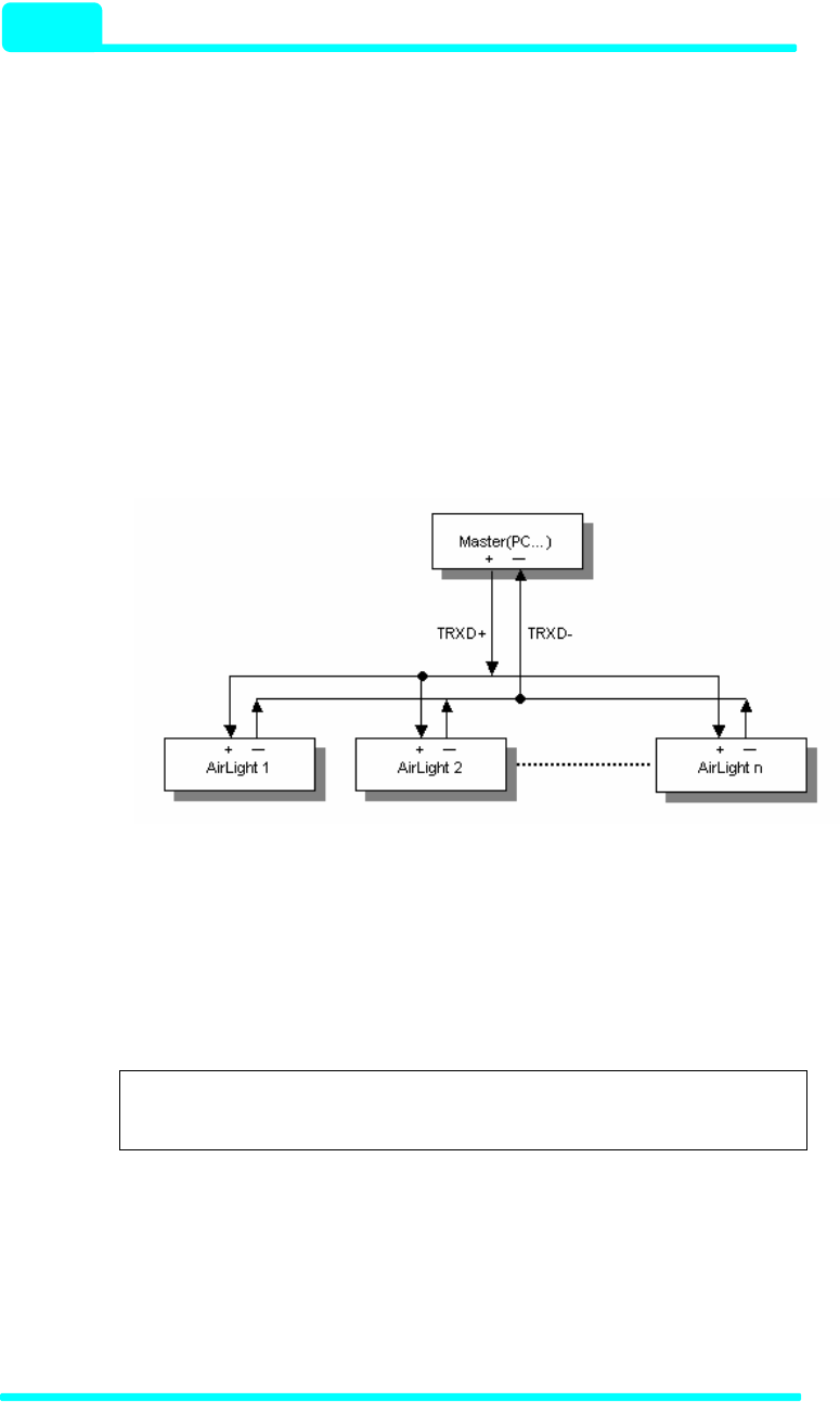
The RS-485 serial communication is a half duplex method. The 1:N
connection is possible. It is possible to connect a master (PC) to many
slaves (AirLight™). Terminal names are "TRX+" and "TRX-". They are
connected in compliance with the polarity. It is recommended to use the
shield cable (AWG-24 Twist) for the communication connection cable. The
connection terminal consists of two terminals, and as for connection, use
solderless terminals.
Figure 3-2 Diagram of Connecting AirLight™ to RS-485
RS-485 communication is used with ALMP, so it is desirable to connect it to
the PC for communication. To connect it to the PC, the RS-485 to RS-232C
converter is needed. This converter isn’t basically provided.
Note : As for the location of the administration terminal of AirLight™,
refer to Chapter 7.
Installation
- 60 / 70 Series
3 - 10
3-5-5. Alignment Bracket
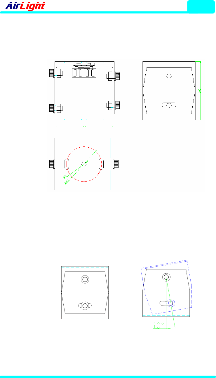
To make tilt easy during AirLight™ installment, the attached alignment
bracket is provided. The dimension of the bracket is displayed in Figure 3-3.
Figure 3-3 Dimension of the Alignment Bracket
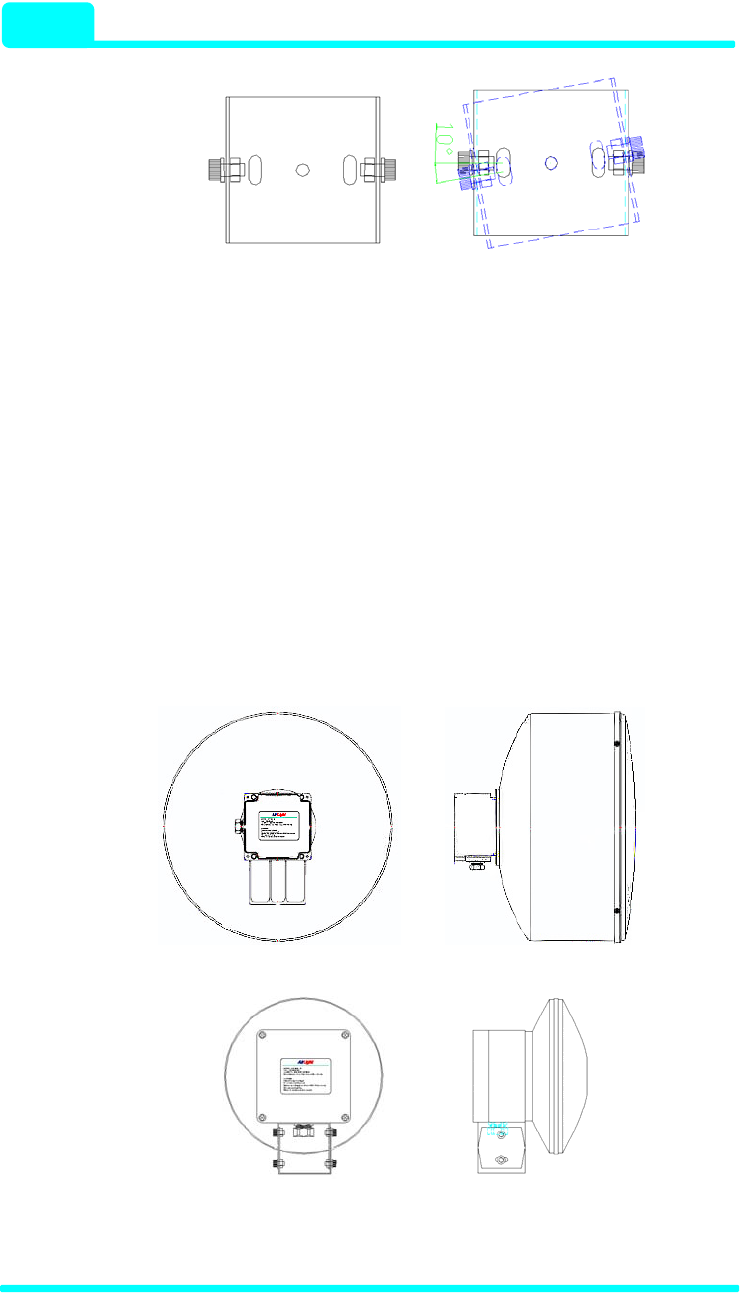
All the bolts for fixing basically use M8. To flexibly set up the direction, the
alignment bracket can be tilted within 10 degrees up or down and 10
degrees left and right are available for left, right, up and down.
(a) Up / Down Angle
COMOTECH CORPORATION
Installation
3 - 11
(b) Right / Left Angle
Figure 3-4 Rotated Angle for Alignment
3-5-6. Flexible Tube Terminal
The protection tube (flexible tube) is needed to protect the optic cable, AC
power line, and RS-485 cable required to connect AirLight™ to Hub(or
Router etc.) and the PC. Hence, AirLight™ provides the hole with the
27mm diameter to connect various cables. This hole is well suited with the
flexible tube with the 22mm diameter. Basically, the flexible tube connector
is attached. Various cables can be used to protect both signal and power
cable, such as flexible tube. Use the electromagnetic shielding protection
tube if possible.
TE1000C-24/ME1000C-24, TE100C-24/ME100C-24
TE1000C-12/ME1000C-12, TE100C-12/ME100C-12
Figure 3-5 Holes for Flexible Tube

Installation
- 60 / 70 Series
3 - 12
3-6. Cabling Check
√ Check if the correct power source is used.
Æ Check if it is AC 100V 240V ∼or DC 48V.
√ Check the connected conditions of the power cable. (Refer to chapter 3
power source terminals.).
Æ Check if the power cable is correctly connected to the power cable.
Æ If the separate power switch is set up, turn it “ON”.
√ After the power is properly supplied, check if the DC power source LED is
lighted.
Æ If it is not lighted, check the power source connection terminal.
√ Check if the optic connector is connected and the OSD LED is lighted.
Æ If it is not lighted, check the cable connection conditions and the
operating conditions of another device. If it is not connected to
another device, the OSD LED is not lighted.
Æ Check if the optic cable is OK.
√ Connect the administrative RS-485 cable to the serial terminal of the PC
(The adaptor is used) and execute ALMP. Then check if it is normally
connected. (Refer to chapter 4 ALMP.)
Æ If communication is not possible, check the cable or program setup.
The detailed adjustment is possible only if communication is possible.
√ Check the receiving power through the management program (ALMP).
Readjust it if needed.
Æ As the received RF power level from ALMP gets larger, the stable
communication quality can be obtained.
COMOTECH CORPORATION

ALMP
4 - 1
4. AirLight™ Monitoring Program (ALMP)
4-1. Introduction
ALMP provides the following functions by easily grasping the current state
and abnormal signs and by having the user administrate them more easily. It
checks RF receiving power, internal temperature, various cable connection
statuses, alarms, warns abnormalities. Furthermore, the record function of
the program makes it possible to track the previous AirLight™ status.
▶Major Functions
√ Sense of RF receiving power
√ Check of internal temperature of AirLight™
√ Check of optic cable connection status
▶Additional Functions
√ Alarm and warning functions
√ AirLight™ management function (up to 9 units)
√ Function to output AirLight™ status
√ Function to record AirLight™ status

ALMP
- 60 / 70 Series
4 - 2
4-2. Installation
▶Recommended Operating Environment
√ CPU: Intel Pentium Processor Celeron 400MHz or higher
√ RAM: 64 Mbytes (minimum 16 Mbytes)
√ Hard Disk: 20 Mbytes (minimum 10 Mbytes)
√ OS: Window 98, NT/2000, XP[Service Pack 2.0]
√ Video mode: 1024 X 768 (Minimum: 640 X 480)
√ Interface: Serial COM port (required)
√ Others: RS232 to RS485 converter
Setup▶
√ Copy the AirLight folder to desired place of the hard disk.
√ Execute ALMP.EXE in the AirLight\ALMP folder.
COMOTECH CORPORATION

ALMP
4 - 3
4-3. Getting Start
4-3-1. Starting ALMP
In order to start ALMP, open the folder where the executable file was copied.
If the executable file appears, double-click the ALMP.EXE file to execute the
program. If the program is executed, the screen like Fig. 4-1 appears, and
the progress bar is executed. If the progress bar is fully progressed, the
window to set up the COM port appears as Fig.4-2.
Figure 4-1 ALMP Progress Window
4-3-2. Program Terminal Setup
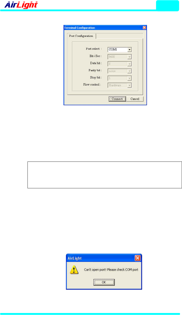
Terminal setup window to select the COM port is shown in Fig. 4-2. For
reference, default values are set up for the other items except for Port
Select. They can’t be changed.
1) Port select: COM port is selected.
2) Bit/Sec: Transmission rate is selected.
3) Data bit: Number of data bits transmitted is selected.
4) Parity bit: Parity to transmit after the parity check is selected.
5) Stop bit: Number of stop bits is selected.
6) Flow control: Flow control is selected.
ALMP
- 60 / 70 Series
4 - 4
Figure 4-2 Program Terminal Setup Window
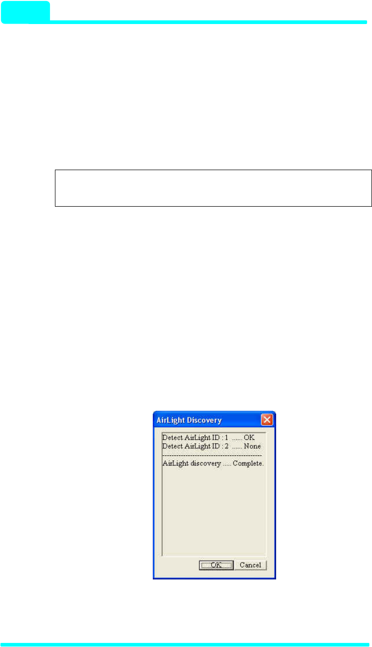
Press the Connect button after setting up the port and the program window
is activated. If the selected port is in use, the warning window such as Fig. 4-
3 appears.
Note :
If the warning window appears, press the OK button to
close the warning window and check if the selected port
is in use.
If the selected port is open, press the Connect button after closing the port
and the program window is activated. Pressing the Cancel button makes
the program executed with the COM port not opened.
When the program was executed without opening the port, the program
information file (AirLight.ini) has to be opened to activate the COM port so
that the program normally operates.
Figure 4-3 Port Open Warning Window
COMOTECH CORPORATION
ALMP
4 - 5
4-3-3. Program Explanation
1> Program Operation
If the port setup is completed, the program window is activated. In case, the
information file exists, the program operates based in the file.
Note : The program information file is automatically created in
the folder where the executable file is located.
If the program is initially executed, the program information file is created
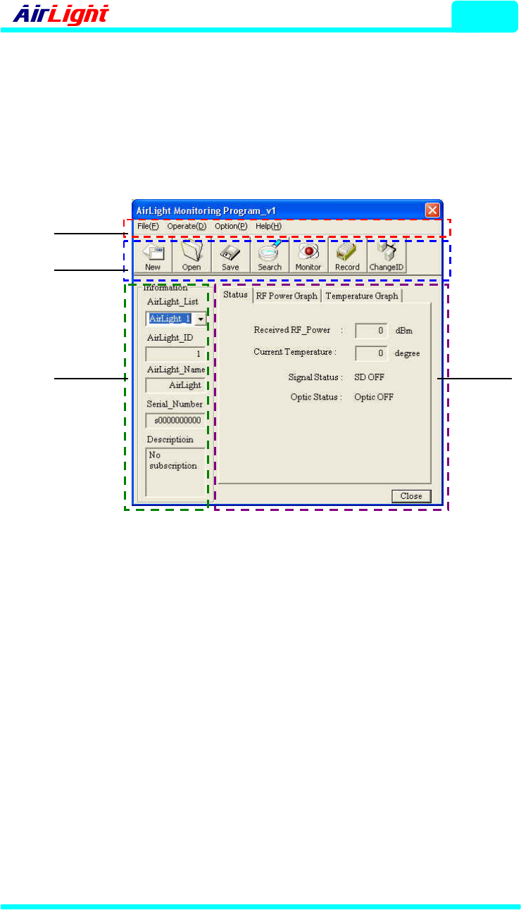
and the automatic search function is executed. The search result shows up
as in Fig. 4-4. If the search is completed, “AirLight discovery ..Complete.”
message is displayed.
Pressing the OK button after the message is displayed makes the searched
equipment registered in AirLight_List of Fig, 4-5. If there are several
equipments searched, they are registered in the ascending order of
equipment IDs.
To stop the search during the execution of the automatic search function,
press the Cancel button to stop the search.
Figure 4-4 Equipment Detection Result Window
ALMP
- 60 / 70 Series
4 - 6
2> Main Window
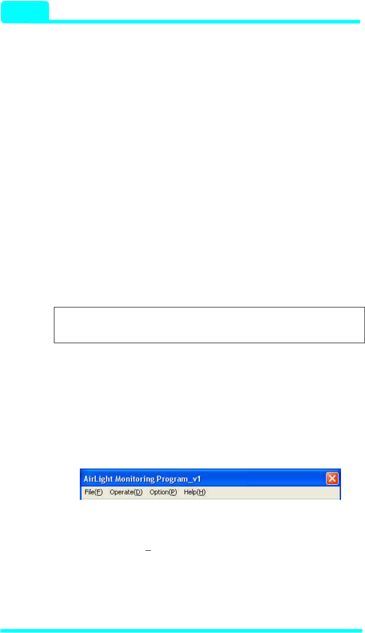
Main window of the ALMP program is shown in Fig. 4-5. The program is
composed of four functional components. Each component comprises
menus, icon buttons, the information display part, and the status display part.
Menus
Icon
Buttons
Information
Display Status
Display
Figure 4-5 Main Window of the Program
3> Program Configuration
As explained in the Main window, the program configuration consists of
menu items and icon buttons related to program operation events, the
information display part to display the equipment information, and the status
display (Status, RF Power Graph, and Temperature Graph) to display the
monitoring status. The program configuration can be summarized as follows.
(1) Menu
The menus consist of File, Operate, Option, and Help and contain the
events related to the entire program operation.
COMOTECH CORPORATION
ALMP
4 - 7
(2) Icon Button
They are the icon type buttons triggering the events related to the program
operation. They show the functions frequently used in the menu function.
(3) Information Display
It is the part displaying the list of searched equipments and the status of
equipments selected from the list.
(4) Status Display
It is the part showing the equipment operation status when the monitoring
function is executed and shows the received power, internal temperature,
signal status, and optic cable connection status. Selecting RF Power Graph
or Temperature Graph from the horizontal tabs makes you check the
operatiing status with a graph.
Note : If the monitoring function is not operating, default
values are displayed.
4> Program Details
The detailed operations of the main program can be classified into the menu
items shown in Fig. 4-6. Each menu item contains submenu items
corresponding to the menu and can be also called with Alt+Key (Ex.: File ->
Alt+F).
Figure 4-6 Menu Screen
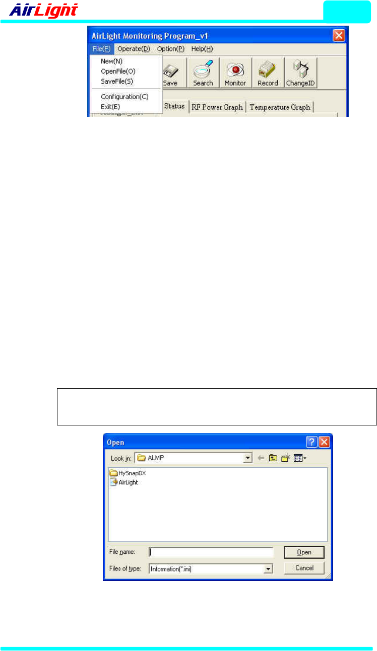
(1) Menu -> File [File(F)]
It represents operations such as program re-run, file related matters,
program configuration and program termination. File items are classified into
five items as in Fig. 4-7.
ALMP
- 60 / 70 Series
4 - 8
Figure 4-7 Sub-items of ‘File’
(1.1) New
The current connection is discontinued, and it starts with the new connection.
Pressing New makes the terminal setup window activated for the new
connection.
(1.2) OpenFile
If there is an information file (AirLight.ini) already saved or kept, it can be
recalled and used. Pressing OpenFile makes the file input window shown in
Fig. 4-8. If the information file is opened in the file input window, the terminal
connection status and the equipment list already registered are recorded
and the program window will be activated.
If the selected file is not correct file, the warning window shown in Fig. 4-9
will be activated. Press OK button and select the correct file.
Note : If the correct information file is not exist, select New to
create a new information file.
Figure 4-8 File Open Window
COMOTECH CORPORATION

ALMP
4 - 9
Figure 4-9 File Open Error Warning Window
(1.3) SaveFile
The current status is saved. The terminal setup information and the
equipment list registered in the program are saved with the information file
type (AirLight.ini). The file can be used later on with FileOpen. Open
AirLight.ini file in the folder where ALMP.exe file is located to check the
current record file.
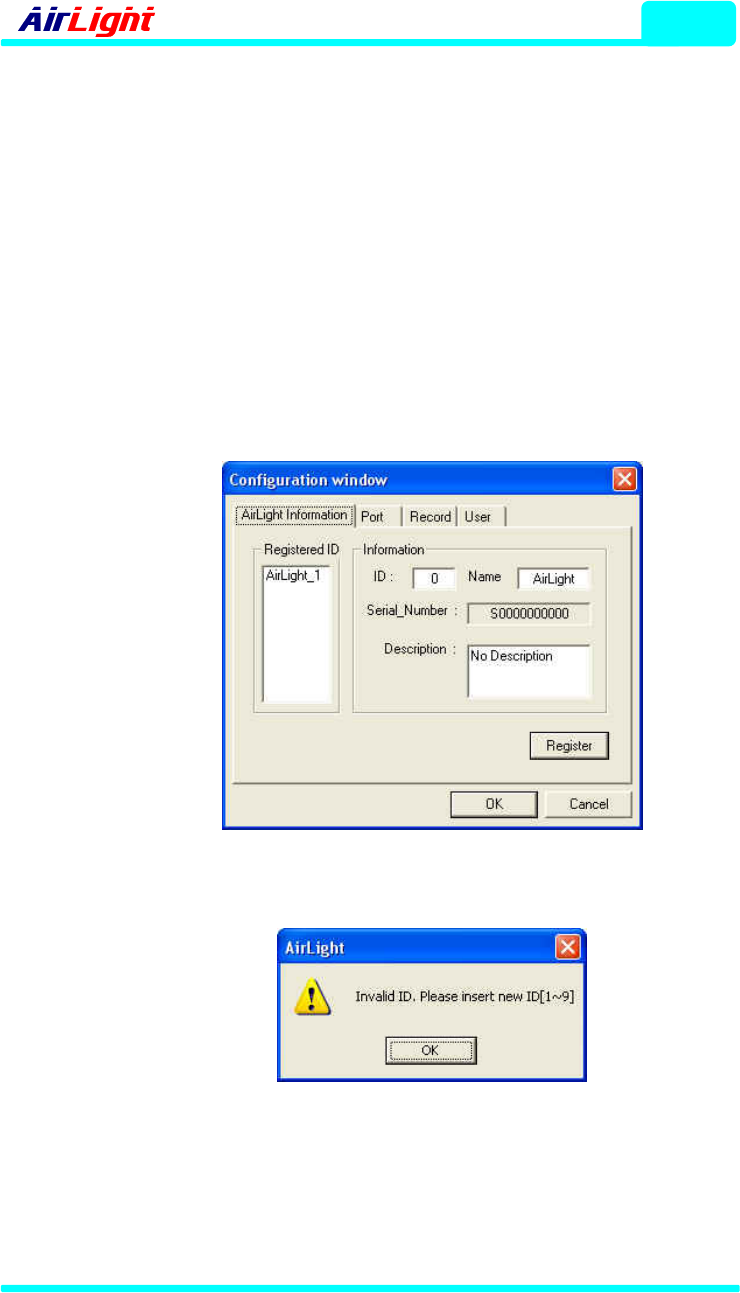
(1.4) Configuration
The program information file is created, or the current information file is
changed. If there is an information file already created, the file data are
displayed in the data display part of the Configuration window.
9 AirLight Information: The equipment list currently registered can be
checked, and the properties of equipments registered can be changed.
Moreover, the new equipment list can be added if needed by the user.
Note :
As far as the information on an equipment registered,
double-clicking the equipment ID in Registered ID
makes the details show up in the information part.
ALMP
- 60 / 70 Series
4 - 10
To change equipment properties, modify the item needed to be changed
and press the following Register button. In order to register a new
equipment, enter equipment properties and press the Register button.
Then a new equipment is registered in Registered ID. If the OK button
is pressed after registration, the modified equipment is available and the
equipment connection can be checked. The registration of a new
equipment is allowed in the permitted ID range [1~9], and the warning
window shown in Fig. 4-11 is activated for the other values. Press the
OK button, when Warning window appears and then register the
correct equipment number within the permitted ID range.
Figure 4-10 AirLight™ Information Configuration Window
Figure 4-11 Equipment ID Input Warning Window
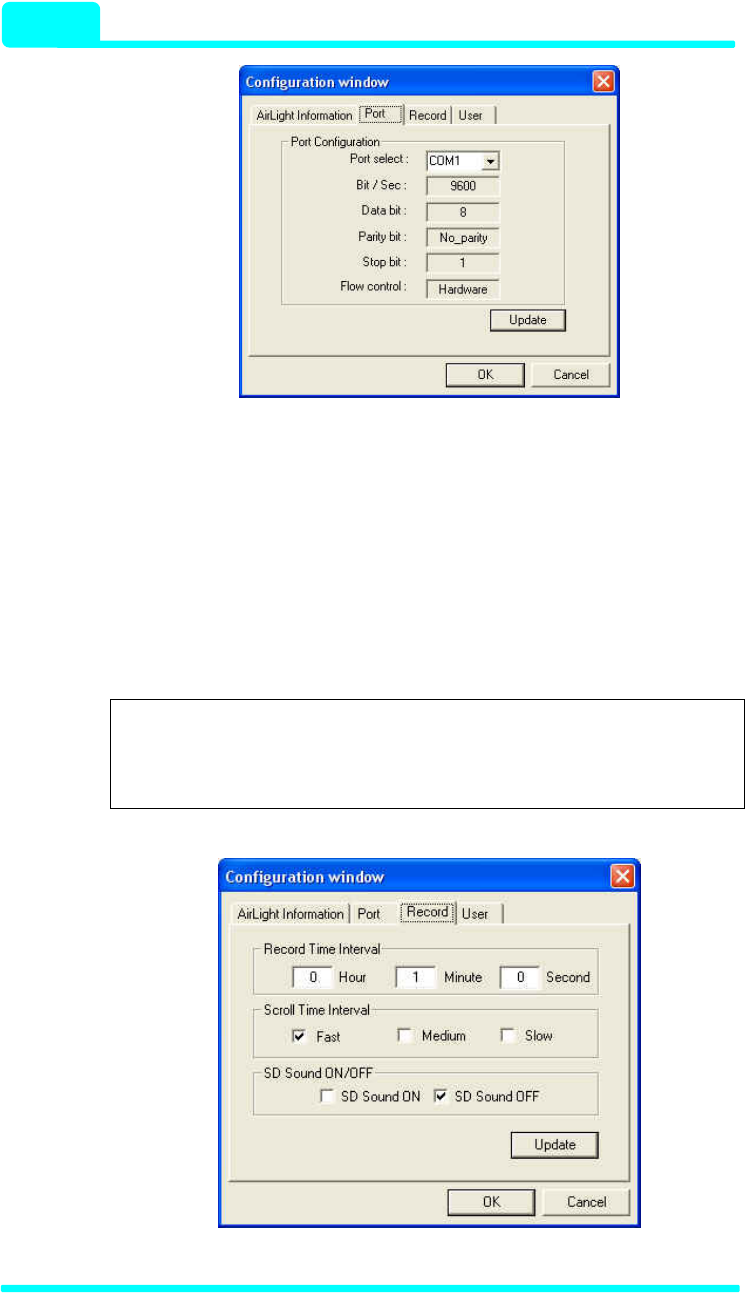
9 Port: The port setup can be modified just like the terminal setup.
Modifying the port currently used, change the Port select part and
press the update button to register the change.
COMOTECH CORPORATION
ALMP
4 - 11
Figure 4-12 Port Setup Configuration Window
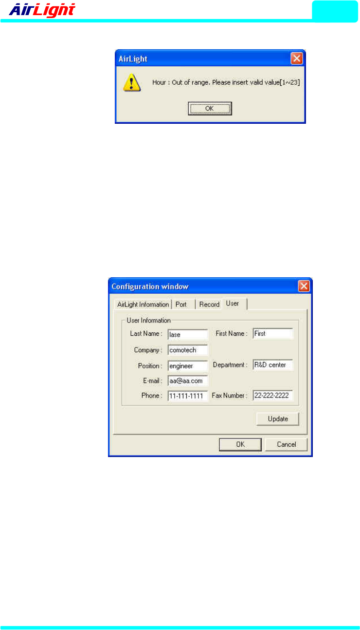
9 Record: It is the part to set up the storage time of the record file, graph
scroll time, and On/Off of the warning sound depending on the signal
status. Input the data to change and press the Update button to
register the change. If the record time interval is not correctly entered,
the warning window shown in Fig. 4-14 is activated.
Note :
If the time input warning window appears, check the
time range of the warning window and enter the correct
value within the range.
Figure 4-13 Additional Function Configuration Window
ALMP
- 60 / 70 Series
4 - 12
Figure 4-14 Record Time Input Warning Window
9 User: This is the part to record user information. User information such
as user name, company information, e-mail address, phone number,
fax number, etc. is recorded. Enter necessary items and press the
Update button for registration. After the setup is all over, press the OK
button and register the information file again, and then the program
setup will be over.
Figure 4-15 User Information Window
(1.5) Exit
The program is terminated.
COMOTECH CORPORATION
ALMP
4 - 13
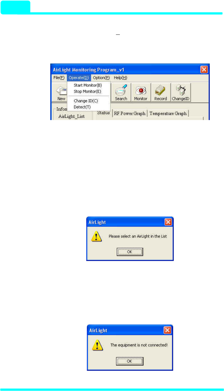
(2) Menu -> Operation [Operate(D)]
The operation to communicate with the selected equipment can be selected.
Operation items are displayed with 4 operations as in Fig. 4-16.
Figure 4-16 Sub-items of the ‘Operate’ Item
(2.1) Start Monitor
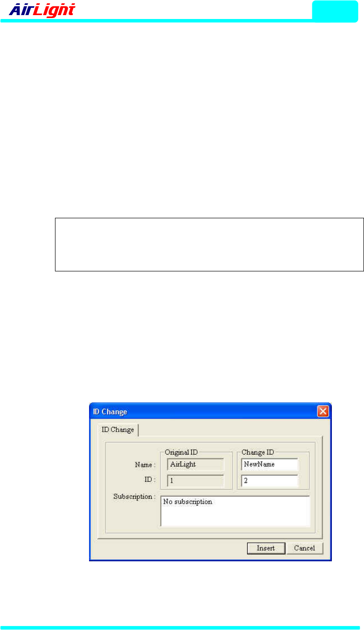
The monitoring function of the selected equipment is started. If an
equipment isn’t selected in AirLight_List, the warning window shown in Fig.
4-17 is activated. Press the OK button in the warning window and select the
equipment from AirLight_List. Selecting the equipment and pressing Start
Monitor makes the monitoring function execute.
Figure 4-17 Selection Error Warning Window
If there is a problem with the line or data loss during monitoring, the warning
window shown in Fig. 4-18 is displayed. Press the OK button and check the
line or AirLight equipment status.
Figure 4-18 Connection Error Window
ALMP
- 60 / 70 Series
4 - 14
(2.2) Stop Monitor
The monitoring function of the selected equipment is stopped.
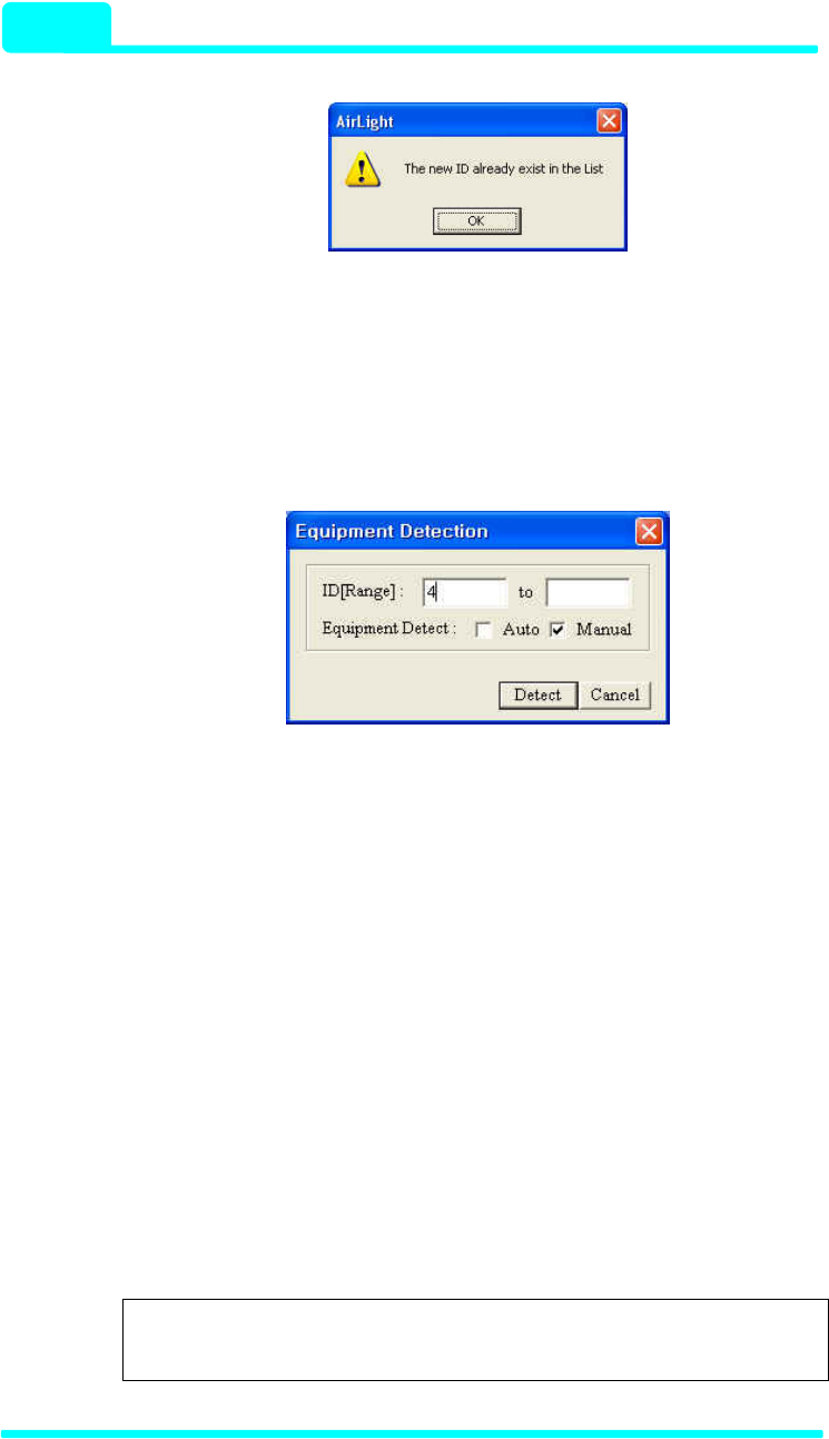
(2.3) Change ID
The ID, name and details of the selected equipment are modified. Select the
equipment in AirLight_List and press Change ID, and then the ID Change
window shown in Fig. 4-19 is activated. The name, ID and details of the
selected equipment are displayed, and the existing name and ID are
displayed with the inactivated status.
Note :
If a name and details are to be changed, enter the
existing ID in Change ID and enter the name and details
to change.
Enter the name and ID to change in the Change ID part. As for details,
erase the existing details and prepare them again. Press the Insert button
after input to change the equipment ID.
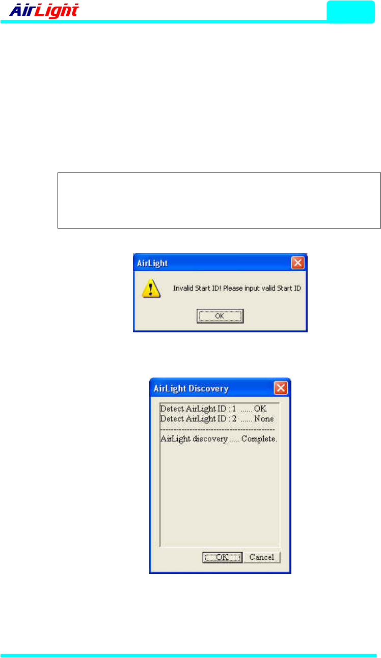
If a new ID specified in Change ID is used, the warning window shown in
Fig. 4-20 is activated. Press the OK button in the warning window and check
if the new ID is in AirLight_List.
Figure 4-19 ID Change Window
COMOTECH CORPORATION
ALMP
4 - 15
Figure 4-20 ID Change Error Window
(2.4) Detect
The function makes it possible to automatically or manually detect the PC in
which programs are currently executed and for the equipments connected to
the PC. Pressing Detect to execute this function makes the Equipment
Detection window shown in Fig. 4-21 activate.
Figure 4-21 Equipment Detection Window
Checking the Auto check box of Equipment Detection window makes the
ID(Range) part inactivated, and checking the Manual check box makes the
ID(Range) part activated. Auto is the function to automatically detect
equipments, and equipments from 1 to 9 are detected. Manual is the
function to manually detect equipments. It executes the function to get the
starting equipment ID or starting and ending IDs and detect equipments
within the range entered. Entering the ID of the equipment to detect in the
Equipment Detection window and pressing the Detect button make the
detection start. If the ID was not entered or the value beyond the range
between 1 and 9 was entered after selecting Manual, the warning window
shown in Fig. 4-22 shows up.
Note : If the detection range is not correct, the equipment is
not detected. Check the input value one more time.
ALMP
- 60 / 70 Series
4 - 16
If the entered ID is correct, the detection result window will appear as in Fig.
4-23. The detection result is displayed with the input ID and detection result
(OK or None). If the equipment detection is completed, the message,
“AirLight discovery .. Complete.” is displayed. After the message is displayed,
press the OK button to close the detection result window. Pressing the
Cancel button during detection can stop the detection.
Note :
Pressing the Cancel button during detection stops the
detection in progress. Check the searched equipment
and stop the detection function.
Figure 4-22 Equipment Detection Error Window
Figure 4-23 Equipment Detection Status Display Window
COMOTECH CORPORATION
ALMP
4 - 17
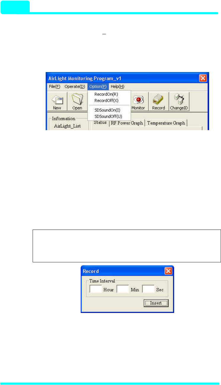
(3) Menu -> Option [Option(P)]
The additional function is provided in the program. There are functions such
as monitoring status record and occurrence of the effect sound depending
on the monitoring status as in Fig. 4-24.
Figure 4-24 Sub-items of the Option
(3.1) RecordOn
The types of current equipment status (Record Time, ID, RF-Power,
Temperature, SD Status and Optic Status) are saved with the file. Pressing
RecordOn makes the time input window activated.
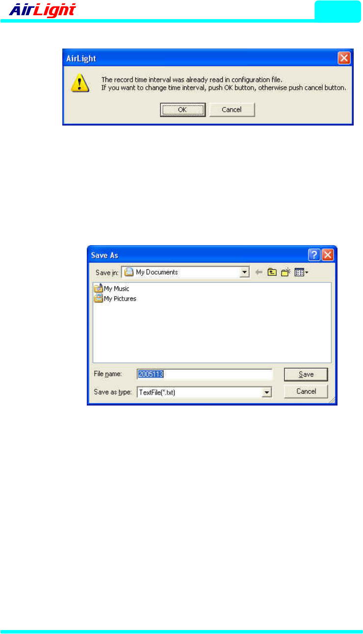
If the record time interval is saved in the information file or the time interval
was entered before, the warning window shown in Fig. 4-26 will appear.
Note :
The existing time interval is recorded in the information
file. Refer to the [Record/Sound] part of the information
file.
Figure 4-25 Record Time Input Window
To change the time interval, press the OK button and enter the time interval.
To maintain the existing time interval, press the Cancel button and use the
existing value. If the Insert button is pressed after the time is entered or the
existing value is read, the Save As window shown in Fig. 4-27 is activated.
ALMP
- 60 / 70 Series
4 - 18
Figure 4-26 Record Time Warning Window
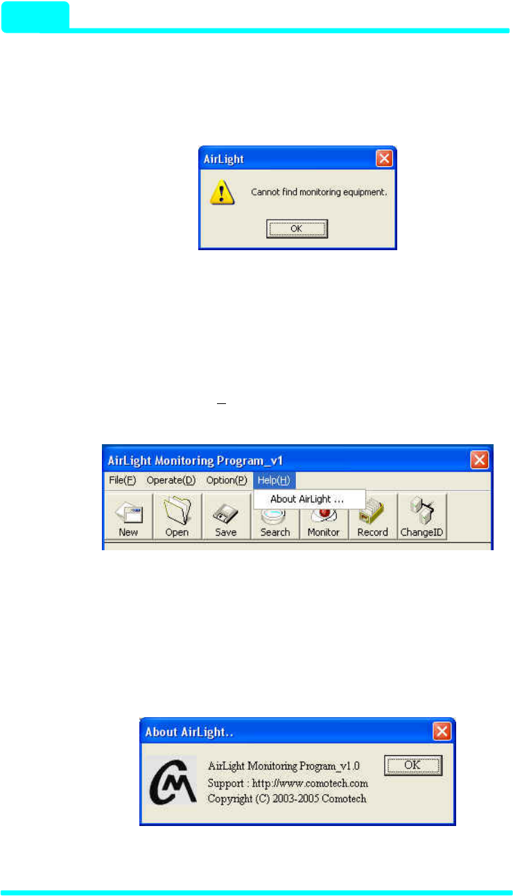
When the Save as File window is activated, entering the file name to record
and pressing the Save button makes the equipment status recorded in the
designated file. The file is saved in the general text document format, and
the file extension (*.txt) is automatically inserted.
Figure 4-27 Save as Record File Window
(3.2) RecordOff
The status of being recorded is stopped. If RecordOn is inactivated, it is
being recorded, so recording can be stopped by pressing RecordOff.
(3.3) SDSoundON
The warning can be sounded depending on SD(Signal Detect) Status. If
SDSoundON is pressed, the alarm is sounded at the fixed time (in case of
SD Status: SD ON). The SDSoundON operation occurs while monitoring
the particular equipment. If there is no equipment being monitored, the
warning window shown in Fig. 4-28 is displayed. Operate it after pressing
COMOTECH CORPORATION
ALMP
4 - 19
the OK button in the warning window and starting the monitoring of the
particular equipment.
The SDSoundON function continues until SDSoundOFF operation occurs.
Hence, it operates even though the monitoring function is rerun.
Figure 4-28 SD Sound Warning Window
(3.4) SDSoundOff
The alarm function based on SD Status is stopped.
(4) Menu -> Help [Help(H)]
The Help with the program can be checked.
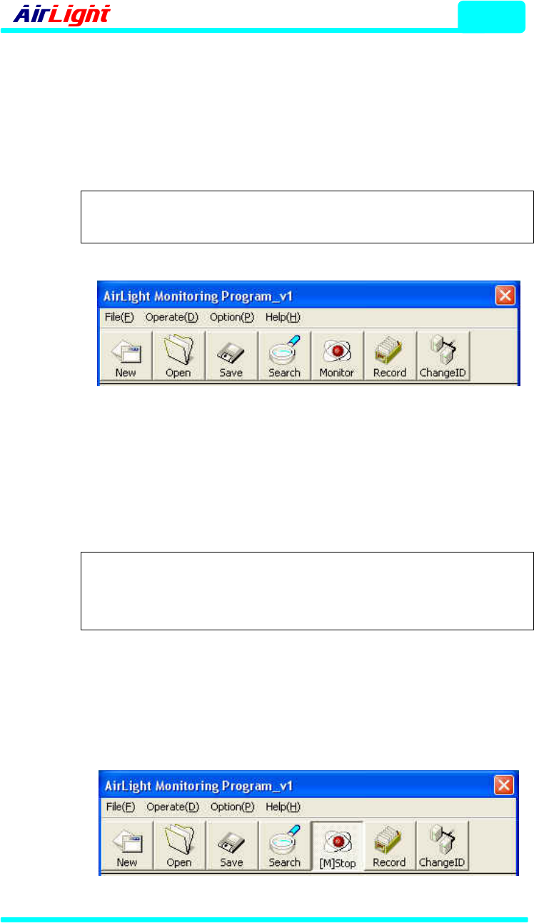
Figure 4-29 Sub-items of the Help
(4.1) About AirLight
Pressing ‘About AirLight…’ makes the program information shown in Fig. 4-
30 displayed. Program version information and web site information on
technical support can be checked in order.
Figure 4-30 Program Information Window
ALMP
- 60 / 70 Series
4 - 20
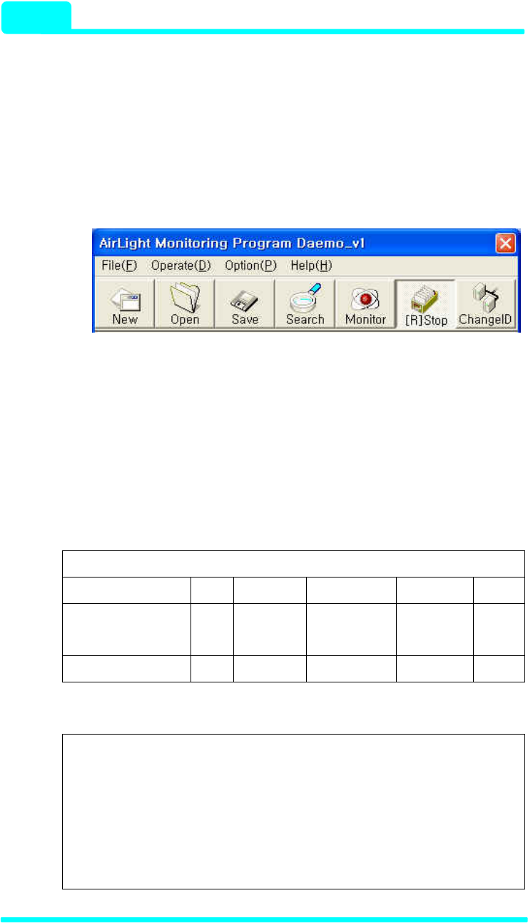
5> Icon Buttons
The functions needed for program execution can be used with icon buttons.
Each icon button is the same as the execution of the Menu->Item and
provides a far friendlier interface. Icon buttons are available as in Fig. 4-31.
Note : As for the explanation of each function, refer to the
program details of the item 4 of 4-3-3.
Figure 4-31 Icon Button
Pressing the Monitor button to check the status of a particular equipment
makes the Monitor button converted to the pressed status as in Fig. 4-32
and the Monitor part change to [M]Stop.
Note :
If the equipment is disconnected, [M]Stop changes to
Monitor with the connection termination message
displayed.
In order to stop monitoring, pressing [M]Stop button makes the monitoring
function stopped, and the [M]Stop part changes to Monitor again. The
detection function can’t be used during monitoring, so pressing the Search
button doesn’t make any events occur.
Figure 4-32 Monitor Execution
COMOTECH CORPORATION
ALMP
4 - 21
If the Record button is pressed to save the equipment status, the ongoing
status can be saved at the input time intervals. Just like the Monitor
operation, pressing the Record button makes it converted to the pressed
status as in Fig. 4-33, and the Record part changes to [R]Stop. In order to
stop the Save function, pressing the pressed [R]Stop button makes the
Save function stopped. At this time, [R]Stop part changes to Record again.
Figure 4-33 Record Execution
6> Save File Formats
Executing the Record function creates the file to record the current
equipment status. The saved files are stored with the formats shown in Table
4-1. The data actually saved appear with the formats shown in Table 4-2.
Table 4-1 Record File Formats
2005-00-00[Year-Month-Day]
hh:mm:ss ID RF Temper SD_Status Optic
[Hour:Minute:Second] [ID] [RF power] [Temperature] Signal
Statis
Optic
Cable
00:00:00 0 -20 38 ON OFF
Table 4-2 Record File Types
2005-01-19
hh:mm:ss ID RF[dBm] Temper SD_Status Optic
17:05:29 2 -38 26 ON OFF
17:06:29 2 -39 27 ON OFF
17:06:29 2 -39 27 ON OFF
17:06:29 2 -38 28 ON OFF

ALMP
- 60 / 70 Series
4 - 22
4-3-4. Examples of Program Use
Operating procedures are provided to briefly explain how to operate the
program. First, copy the distributed program to the particular system folder.
The file is organized with the ALMP.exe file. Click and execute the program.
The ‘Start’ window that is the startup window is activated. When the ‘Start’
window disappears as the progress bar advances, the ‘Terminal Setup’
window is activated. Check the status of connection between the equipment
and the system and the serial port [COM1, COM2, etc.] connection status.
Select the port connected to the ‘Port select’ part of the ‘Port Setup’ window.
After the selection is made, press the ‘Connect’ button to activate the
terminal connection. If the connection is completed, the main program
window is activated and the equipments currently connected are
automatically detected. The range of ID 1~9 is detected and the equipment
detected during each detection stage is automatically registered in
AirLight_List. The detection can be stopped by pressing the ‘Cancel’ button
during automatic detection. If the detection is completed, check the
equipments connected to the detection result window, press the ‘OK’ button,
and close the result window. The registered equipment list can be checked
in AirLight_List, and the current configuration status is automatically saved in
the program information file. Now the monitoring function is executed to
check the registered equipment status. As for the monitoring function, select
the particular equipment in AirLight_List and press the ‘Monitor’ button for
execution. If another equipment status needs to be checked, release the
function of the equipment being monitored and execute the monitoring
function of the particular equipment again. In order to record the current data,
press the ‘Record’ button and enter the record time interval in the time input
window. If the record file name is entered after the time interval is entered,
the data can be recorded with the file.
COMOTECH CORPORATION

5 - 1
Troubleshooting
5. Troubleshooting
The basic method to check the AirLight™ status is to use ALMP. If AirLight™
doesn’t operate as it does, execute ALMP to check the operation status of
AirLight™.
5-1. General ALMP Features
An IBM compatible Personal Computer (PC) is needed to execute ALMP. As for the
connection between AirLight™ and the PC, refer to chapter 3. If the installed
AirLight™ is detected and monitoring is started by executing ALMP, the following
items can be checked.
√ RF Receiving Power – The receiving power is displayed in real-time.
√ Internal Temperature of AirLight
√ Network Connection Status – Signal Status and Optic Status
5-2. Problem Solving
Check the following before asking for after sales service center.
1. AirLight™ is not detected in ALMP.
Problem Cause Action
Power source terminal connection
error
Check the connection method and
connect it again.
Cable disconnection Replace it with a new cable
Power Source
Switched ‘Off’ Have the switch ‘On’.
Terminal connection error Check the connection method and
connect it again.
Cable disconnection Replace it with a new cable
A bad converter Replace the converter with a new
one. (Contact the vendor.)
PC port setup error Set it up with the used port.
Administration
Communication
A bad PC serial port Contact the PC vendor.

Troubleshooting
- 60 / 70 Series
5 - 2
2. ‘Received RF Power’ is “LOW” or ‘Signal Status’ is “OFF”.
Problem Cause Action
Power Source The equipment power source on the
other side is “Off”.
Authorize the power source
normally.
Wrong direction Readjust the direction.
Dirt or dust in the antenna Clean the antenna.
The setup distance between
equipments is exceeded.
Set it up with less than the
effective distance again.
Setup
Rotate and install the equipment on
the one side.
Reinstallation (Standardize the
rotation direction.)
Attenuation due to heavy rain Set it up again considering the
local rainfall.
Environment
Antenna burying due to snow fall Snow removal operations
3. ‘Optic Status’ comes out with “OFF”.
Problem Cause Action
TX and RX terminal connection error Check the connection method and
reconnect it.
Different optic standards Check standards and replace the
cable with a new one.
Optic Cables
Dirt or dust and breakage in the optic
terminal
Clean the terminal and replace the
cable with a new one.
The connection equipment on the
other side is “Off”.
Authorize the power source
normally.
Connection
Equipment Connection equipment error Check the vendor.
COMOTECH CORPORATION
6 - 1
Specification
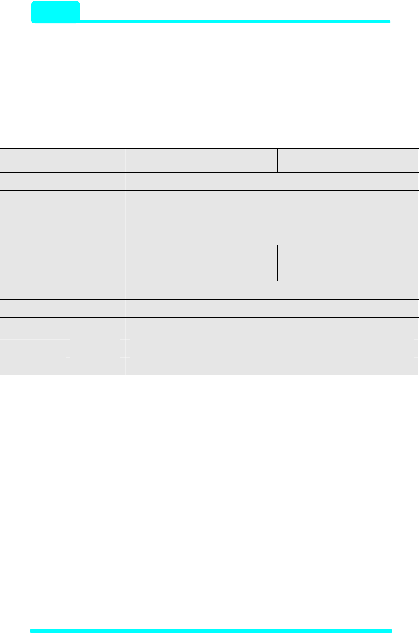
6. Specification
6-1. AirLight™ 70 Series Typical Specification
Parameter TE1000C-24
TE1000C-12 TE100C-24
TE100C-12
Frequency Range 71~76GHz
Output Power +17dBm (50mW)
Modulation ASK
Main Power +48Vdc or AC100~240(50~60Hz)
Interface (Multimode) Optic MMF 850nm, LC-type Optic MMF 1310nm, LC-type
Data Rate 1.25Gbps 125Mbps
Operation Temperature -30 ~ +70°C
Size (WxHxD) 622x622x492(2ft), 304x342x220(1ft),180x180x100(module only)
Weight 17kg(37.5lbs, 2ft) / 6kg(12.2lbs, 1ft)
Type Cassegrain
Antenna Size 2ft(24") / 1ft(12")
Specification
- 60 70 Series 6 - 2
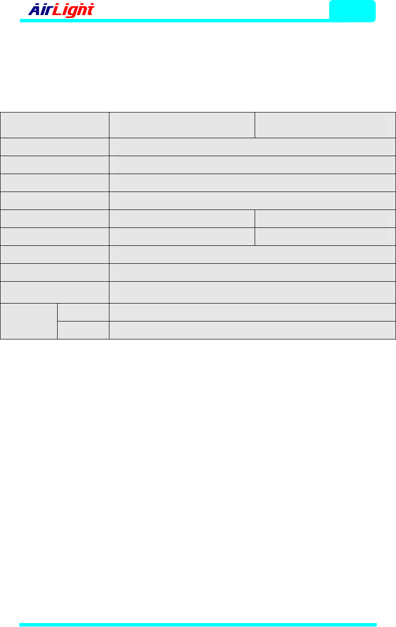
6-2. AirLight™ 60 Series Typical Specification
Parameter ME1000C-24
ME1000C-12 ME100C-24
ME100C-12
Frequency Range 57~64GHz1)
Output Power +10dBm (10mW)
Modulation ASK
Main Power +48Vdc or AC100~240(50~60Hz)
Interface (Multimode) Optic MMF 850nm, LC-type Optic MMF 1310nm, LC-type
Data Rate 1.25Gbps 125Mbps
Operation Temperature -30 ~ +70°C
Size (WxHxD) 622x622x492(2ft), 304x342x220(1ft),180x180x100(module only)
Weight 17kg(37.5lbs, 2ft) / 6kg(12.2lbs, 1ft)
Type Cassegrain
Antenna Size 2ft(24") / 1ft(12")
1) 59~66GHz TELEC(Japan) specification available.
COMOTECH CORPORATION
Terminal Location
7 - 1
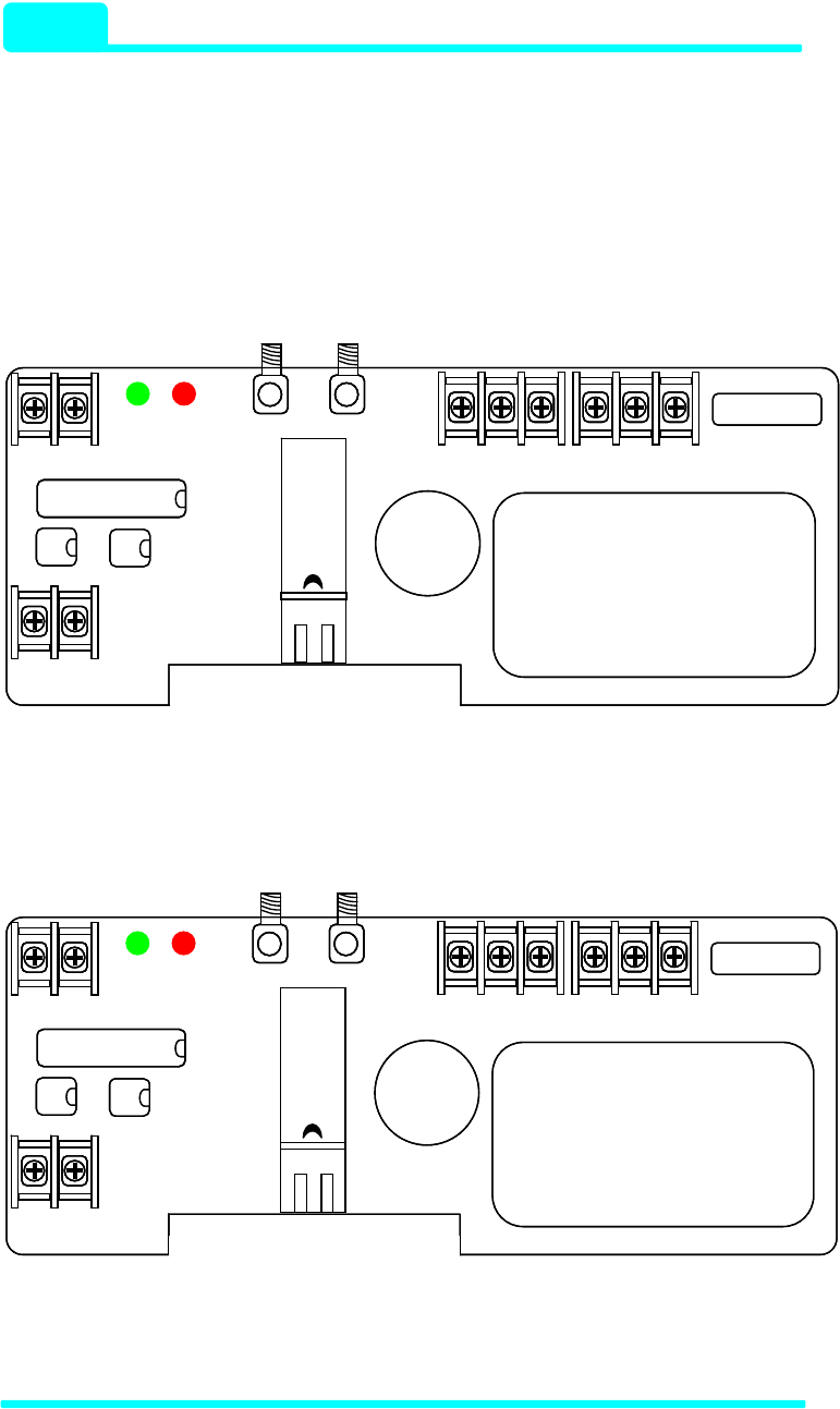
7. Terminal Location
7-1. The Terminal Location of TE1000C-24/12, ME1000-24/12
▶For AC Power PCB
AC-DC Converter
PWR OSD
u-processor
VCC GND
Optic
Transceiver
FG AC(N) AC(L)
IN OUT
RSSI VCC GND
TRX+ TRX-
TX RX
AC-DC Converter
PWR OSD
u-processor
u-processor
VCC GND
Optic
Transceiver
FG AC(N) AC(L)
IN OUT
RSSI VCC GNDRSSI VCC GND
TRX+ TRX-
TX RX
▶For DC Power PCB
DC-DC Converter
PWR OSD
u-processor
VCC GND
Optic
Transceiver
NC (+)V (-)V
IN OUT
RSSI VCC GND
TRX+ TRX-
TX RX
DC-DC Converter
PWR OSD
u-processor
u-processor
VCC GND
Optic
Transceiver
NC (+)V (-)VNC (+)V (-)V
IN OUT
RSSI VCC GNDRSSI VCC GND
TRX+ TRX-
TX RX
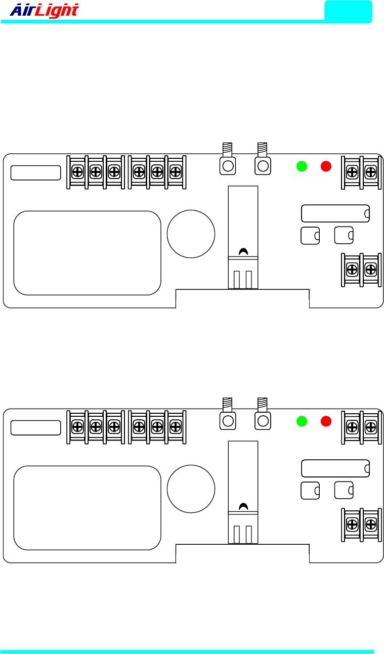
Terminal Loaction
- 60 70 Series 7 - 2
7-2. The Terminal Location of TE100C-24/12, ME100-24/12
▶For AC Power PCB
AC-DC Converter
PWR OSD
u-processor
Optic
Transceiver
IN OUT
GND VCC RSSI
TRX+ TRX-
TX RX
PWR OSD
GND VCCAC(L) AC(N) FG
▶For DC Power PCB
DC-DC Converter
PWR OSD
u-processor
Optic
Transceiver
IN OUT
GND VCC RSSI
TRX+ TRX-
TX RX
PWR OSD
GND VCC(-)V (+)V NC
COMOTECH CORPORATION