Compal Electronics VS500 Single Band CDMA Cellular Phone User Manual technical part
Compal Electronics Inc Single Band CDMA Cellular Phone technical part
UserManual.wiki
>
Compal Electronics
>
VS500 User Manual
>
User Manual technical part
Contents
1.
User Manual
2.
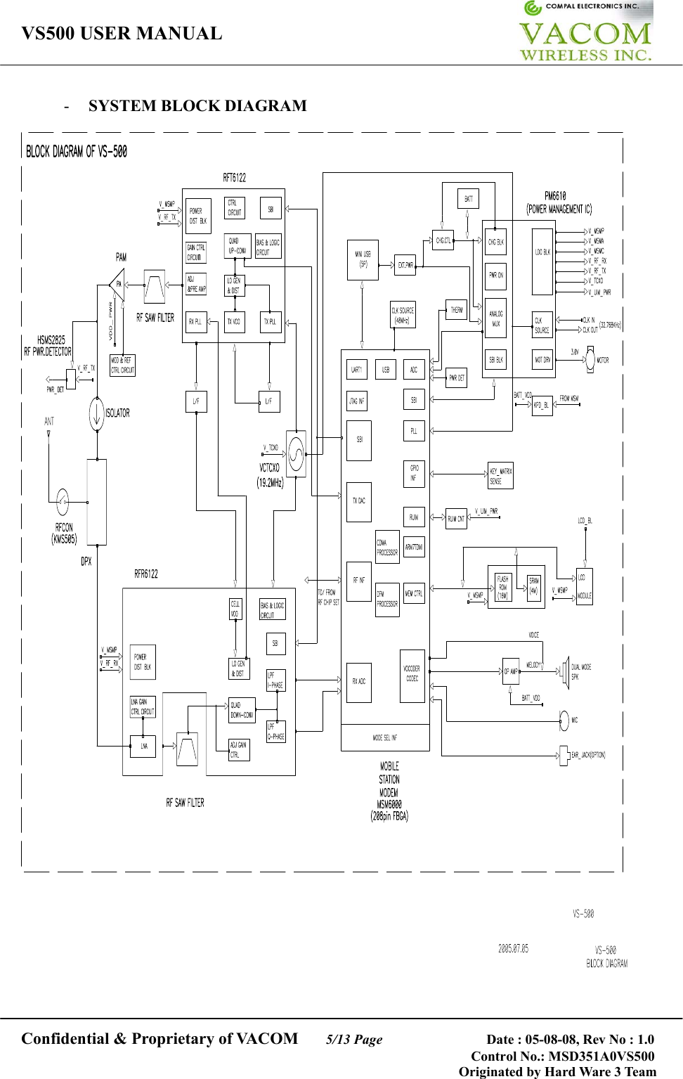
User Manual technical part
User Manual technical part
Navigation menu
Upload a User Manual
Namespaces
Wiki Guide
HTML
PDF
Info
Views
User Manual
Discussion / Help
Navigation