Compaq N620C Evo N610C N600C Series Users Manual Maintenance And Service Guide
Maintenance and Service Guide: Compaq Evo Notebook N620c Series, Compaq Evo Notebook N610c Series, and Compaq Evo Notebook N600c Series c01122797
279362-002 to the manual 33ea71c6-b76c-4e90-80d7-5e079e990055
2015-02-03
: Compaq Compaq-N620C-Evo-N610C-N600C-Series-Users-Manual-468151 compaq-n620c-evo-n610c-n600c-series-users-manual-468151 compaq pdf
Open the PDF directly: View PDF ![]() .
.
Page Count: 215 [warning: Documents this large are best viewed by clicking the View PDF Link!]
- Contents
- Product Description
- Troubleshooting
- Illustrated Parts Catalog
- Removal and Replacement Preliminaries
- Removal and Replacement Procedures
- 5.1 Serial Number
- 5.2 Disassembly Sequence Chart
- 5.3 Preparing the Notebook for Disassembly
- 5.4 Computer Feet
- 5.5 Mini PCI Communications Board
- 5.6 Disk Cell RTC Battery
- 5.7 Keyboard
- 5.8 Memory Expansion
- 5.9 TouchPad
- 5.10 Switch Cover
- 5.11 Display
- 5.12 Top Cover
- 5.13 System Board
- 5.14 Fan
- 5.15 Heat Sink
- 5.16 Processor
- 5.17 DC-DC Converter Board
- 5.18 Modem Cable
- Specifications
- Connector Pin Assignments
- Power Cord Set Requirements
- Screw Listing
- Index
b
Maintenance and Service Guide
Compaq Evo Notebook N620c,
Evo N610c, and Evo N600c Series
Document Part Number: 279362-002
February 2003
This guide is a troubleshooting reference used for maintaining
and servicing the notebook. It provides comprehensive
information on identifying notebook features, components, and
spare parts, troubleshooting notebook problems, and performing
notebook disassembly procedures.
© 2003 Hewlett-Packard Development Company, L.P.
Microsoft and Windows are trademarks of Microsoft Corporation in the U.S.
and/or other countries. Intel, Pentium, and Pentium-M are trademarks of Intel
Corporation in U.S. and/or other countries. All other product names mentioned
herein may be trademarks of their respective companies.
HP shall not be liable for technical or editorial errors or omissions contained
herein or for incidental or consequential damages in connection with the
furnishing, performance, or use of this material. The information in this
document is provided “as is” without warranty of any kind, and is subject to
change without notice. The warranties for HP products are set forth in the
express limited warranty statements accompanying such products. Nothing
herein should be construed as constituting an additional warranty.
Maintenance and Service Guide
Second Edition February 2003
First Edition July 2002
Document Part Number: 279362-002

Maintenance and Service Guide iii
Contents
1 Product Description
1.1 Models . . . . . . . . . . . . . . . . . . . . . . . . . . . . . . . . . . . 1–2
1.2 Features . . . . . . . . . . . . . . . . . . . . . . . . . . . . . . . . . 1–26
1.3 Clearing a Password . . . . . . . . . . . . . . . . . . . . . . . . 1–28
1.4 Power Management . . . . . . . . . . . . . . . . . . . . . . . . 1–29
1.5 Notebook External Components . . . . . . . . . . . . . . 1–30
1.6 Design Overview . . . . . . . . . . . . . . . . . . . . . . . . . . 1–43
2 Troubleshooting
2.1 Computer Setup and Diagnostics Utilities . . . . . . . . 2–1
Selecting Computer Setup or
Compaq Diagnostics . . . . . . . . . . . . . . . . . . . . . . . . 2–1
Selecting from the File Menu. . . . . . . . . . . . . . . . . . 2–3
Selecting from the Security Menu . . . . . . . . . . . . . . 2–4
Selecting from the Advanced Menu. . . . . . . . . . . . . 2–5
2.2 Using Compaq Diagnostics . . . . . . . . . . . . . . . . . . . 2–7
Obtaining, Saving, or Printing
Configuration Information . . . . . . . . . . . . . . . . . . . . 2–7
Obtaining, Saving, or Printing Diagnostic
Test Information. . . . . . . . . . . . . . . . . . . . . . . . . . . . 2–8
2.3 Troubleshooting Flowcharts. . . . . . . . . . . . . . . . . . 2–10

iv Maintenance and Service Guide
Contents
3 Illustrated Parts Catalog
3.1 Serial Number Location . . . . . . . . . . . . . . . . . . . . . . 3–1
3.2 Notebook System Major Components . . . . . . . . . . . 3–2
3.3 Miscellaneous Plastics Kit Components . . . . . . . . 3–16
3.4 Mass Storage Devices . . . . . . . . . . . . . . . . . . . . . . 3–18
3.5 Miscellaneous. . . . . . . . . . . . . . . . . . . . . . . . . . . . . 3–22
4 Removal and Replacement Preliminaries
4.1 Tools Required . . . . . . . . . . . . . . . . . . . . . . . . . . . . . 4–1
4.2 Service Considerations. . . . . . . . . . . . . . . . . . . . . . . 4–1
Plastic Parts . . . . . . . . . . . . . . . . . . . . . . . . . . . . . . . 4–2
Cables and Connectors . . . . . . . . . . . . . . . . . . . . . . . 4–2
4.3 Preventing Damage to Removable Drives . . . . . . . . 4–2
4.4 Preventing Electrostatic Damage . . . . . . . . . . . . . . . 4–3
4.5 Packaging and Transporting Precautions . . . . . . . . . 4–4
4.6 Workstation Precautions . . . . . . . . . . . . . . . . . . . . . 4–4
4.7 Grounding Equipment and Methods . . . . . . . . . . . . 4–5
5 Removal and Replacement Procedures
5.1 Serial Number . . . . . . . . . . . . . . . . . . . . . . . . . . . . . 5–2
5.2 Disassembly Sequence Chart . . . . . . . . . . . . . . . . . . 5–2
5.3 Preparing the Notebook for Disassembly. . . . . . . . . 5–4
5.4 Computer Feet . . . . . . . . . . . . . . . . . . . . . . . . . . . . 5–11
5.5 Mini PCI Communications Board . . . . . . . . . . . . . 5–12
5.6 Disk Cell RTC Battery . . . . . . . . . . . . . . . . . . . . . . 5–15
5.7 Keyboard . . . . . . . . . . . . . . . . . . . . . . . . . . . . . . . . 5–17
5.8 Memory Expansion . . . . . . . . . . . . . . . . . . . . . . . . 5–22
5.9 TouchPad . . . . . . . . . . . . . . . . . . . . . . . . . . . . . . . . 5–25
5.10 Switch Cover . . . . . . . . . . . . . . . . . . . . . . . . . . . . . 5–27
5.11 Display . . . . . . . . . . . . . . . . . . . . . . . . . . . . . . . . . . 5–29
5.12 Top Cover. . . . . . . . . . . . . . . . . . . . . . . . . . . . . . . . 5–32
5.13 System Board . . . . . . . . . . . . . . . . . . . . . . . . . . . . . 5–35

Contents
Maintenance and Service Guide v
5.14 Fan . . . . . . . . . . . . . . . . . . . . . . . . . . . . . . . . . . . . . 5–42
5.15 Heat Sink . . . . . . . . . . . . . . . . . . . . . . . . . . . . . . . . 5–46
5.16 Processor . . . . . . . . . . . . . . . . . . . . . . . . . . . . . . . . 5–50
5.17 DC-DC Converter Board . . . . . . . . . . . . . . . . . . . . 5–52
5.18 Modem Cable . . . . . . . . . . . . . . . . . . . . . . . . . . . . . 5–54
6 Specifications
A Connector Pin Assignments
B Power Cord Set Requirements
3-Conductor Power Cord Set . . . . . . . . . . . . . . . . . . . . . . B–1
General Requirements . . . . . . . . . . . . . . . . . . . . . . . B–1
Country-Specific Requirements . . . . . . . . . . . . . . . . . . . . B–2
C Screw Listing
Index
Maintenance and Service Guide 1–1
1
Product Description
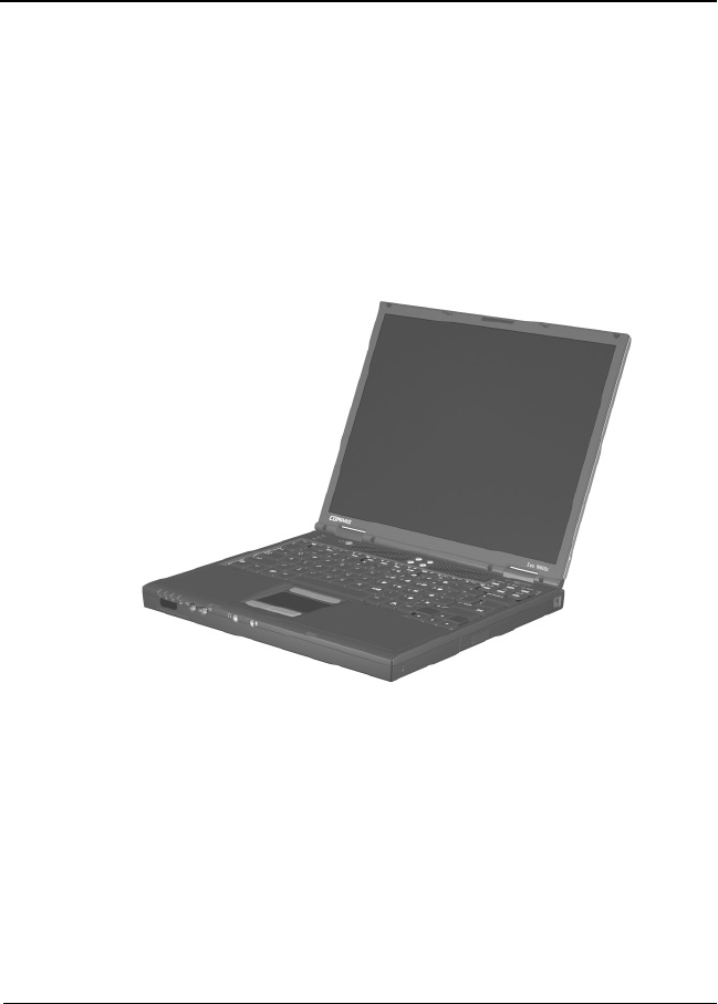
The Compaq Evo Notebook N620c, N610c, and N600c Series
offer advanced modularity, Mobile Intel Pentium 4 and Pentium
III processors with 64-bit architecture, industry-leading
Accelerated Graphics Port (AGP) implementation, and extensive
multimedia support.
Figure 1-1. Compaq Evo Notebook N620c, N610c, and N600c

1–2 Maintenance and Service Guide
Product Description
1.1 Models
Computer models are shown in Tables 1-1 through 1-4.
Table 1-1
Compaq Evo Notebook N620c, N610c, and N600c
Model Naming Conventions
Key
N610 P4 200 P4 40 V C 25 O XXXXXX-XXX
123456789 10
Ke
y Description Options
1 Brand/Series
designator
N = Notebook 620 = N620c series
610 = N610c series
600 = N600c series
2 Processor type P4 = Intel Pentium 4 P3 = Intel Pentium III
P = Intel Pentium-M
3 Processor speed 200 = 2.0 Ghz
190 = 1.9 GHz
180 = 1.8 GHz
170 = 1.7 GHz
160 = 1.6 GHz
150 = 1.5 GHz
140 = 1.4 GHz
130 = 1.3 GHz
106 = 1.06 GHz
866 = 866 MHz
4 Display type/
size/resolution
P = SXGA+ (1400 × 1050)
X = XGA (1024 × 768)
4 = 14.x-inch
5 Hard drive size 60 = 60 GB
40 = 40 GB
30 = 30 GB
20 = 20 GB
15 = 15 GB
10 = 10 GB
6 Optical drive
designator
W = DVD-RW drive
V = DVD-ROM drive
R = CD-RW drive
D = CD-ROM drive
7 Integrated
communication
M = Modem
0 = None
C = Modem/NIC
combination card
Product Description
Maintenance and Service Guide 1–3
8 RAM 51 = 512 MB
38 = 384 MB
25 = 256 MB
12 = 128 MB
9 Operating system 8 = Windows 98 SE
6 = Windows 2000
and Windows XP
2 = Windows 2000
O = Windows XP Pro
E = Windows XP Home
10 SKU#
Table 1-1
Compaq Evo Notebook N620c, N610c, and N600c
Model Naming Conventions
(Continued)
Table 1-2
Compaq Evo Notebook N620c Models
The following Evo Notebook N620c models feature:
■Dual Stick pointing device (TouchPad and pointing stick)
■8-cell, 4.4-Ah lithium ion (Li ion) battery pack
■3-year warranty on parts, labor, and on-site, next business day response
■32 MB of discrete video memory
■no config. code used
N620c P 140 X4 40 C X 25 2
United States DE267A ABA
N620c P 140 X4 40 C X 25 O
United States DE266A ABA
The following Evo Notebook N620c models feature:
■Dual Stick pointing device (TouchPad and pointing stick)
■8-cell, 4.4-Ah Li ion battery pack
■3-year warranty on parts and labor
■32 MB of discrete video memory
■config. code KY2Z
N620c P 160 P4 60 C G 51 2
Brazil
French Canada
DE273A AC4
DE273A ABC
Latin America
United States
DE273A ABM
DE273A ABA

1–4 Maintenance and Service Guide
Product Description
N620c P 160 P4 60 C G 51 O
Brazil
French Canada
DE272A AC4
DE272A ABC
Latin America
United States
DE272A ABM
DE272A ABA
N620c P 150 P4 60 C G 51 2
Asia Pacific
Australia
Belgium
Czech Republic
Denmark
European
International
France
Germany
Greece
Hong Kong
Hungary
Iceland
India
Israel
Italy
Japan
Japan (English)
DE271A UUF
DE271A ABG
DE271A UUG
DE271A AKB
DE271A ABY
DE271A ABB
DE271A ABF
DE271A ABD
DE271A ABV
DE271A AB5
DE271A AKC
DE271A A2M
DE271A ACJ
DE271A ABT
DE271A ABZ
DE271A ABJ
DE271A ACF
Korea
The Netherlands
Norway
People’s
Republic
of China
Poland
Portugal
Russia
Saudi Arabia
Slovenia
Spain
Sweden/Finland
Switzerland
Ta i w a n
Thailand
Tu r k ey
United Kingdom
DE271A AB1
DE271A ABH
DE271A ABN
DE271A AB2
DE271A AKD
DE271A AB9
DE271A ACB
DE271A ABV
DE271A AKN
DE271A ABE
DE271A AK8
DE271A UUZ
DE271A AB0
DE271A AKL
DE271A AB8
DE271A ABU
Table 1-2
Compaq Evo Notebook N620c Models
(Continued)

Product Description
Maintenance and Service Guide 1–5
N620c P 150 P4 60 C G 51 O
Asia Pacific
Australia
Belgium
Czech Republic
Denmark
European
International
France
Germany
Greece
Hong Kong
Hungary
Iceland
India
Israel
Italy
Japan
Japan (English)
DE270A UUF
DE270A ABG
DE270A UUG
DE270A AKB
DE270A ABY
DE270A ABB
DE270A ABF
DE270A ABD
DE270A ABV
DE270A AB5
DE270A AKC
DE270A A2M
DE270A ACJ
DE270A ABT
DE270A ABZ
DE270A ABJ
DE270A ACF
Korea
The Netherlands
Norway
People’s
Republic
of China
Poland
Portugal
Russia
Saudi Arabia
Slovenia
Spain
Sweden/Finland
Switzerland
Ta i w a n
Thailand
Tu r k ey
United Kingdom
DE270A AB1
DE270A ABH
DE270A ABN
DE270A AB2
DE270A AKD
DE270A AB9
DE270A ACB
DE270A ABV
DE270A AKN
DE270A ABE
DE270A AK8
DE270A UUZ
DE270A AB0
DE270A AKL
DE270A AB8
DE270A ABU
Table 1-2
Compaq Evo Notebook N620c Models
(Continued)

1–6 Maintenance and Service Guide
Product Description
N620c P 140 X4 40 C X 25 2
Asia Pacific
Australia
Belgium
Brazil
Czech Republic
Denmark
European
International
France
French Canada
Germany
Greece
Hong Kong
Hungary
Iceland
India
Israel
Italy
Japan
Japan (English)
DE265A UUF
DE265A ABG
DE265A UUG
DE265A AC4
DE265A AKB
DE265A ABY
DE265A ABB
DE265A ABF
DE265A ABC
DE265A ABD
DE265A ABV
DE265A AB5
DE265A AKC
DE265A A2M
DE265A ACJ
DE265A ABT
DE265A ABZ
DE265A ABJ
DE265A ACF
Koran
Latin America
The Netherlands
Norway
People’s
Republic
of China
Poland
Portugal
Russia
Saudi Arabia
Slovenia
Spain
Sweden/Finland
Switzerland
Ta i w a n
Thailand
Tu r k ey
United Kingdom
United States
DE265A AB1
DE265A ABM
DE265A ABH
DE265A ABN
DE265A AB2
DE265A AKD
DE265A AB9
DE265A ACB
DE265A ABV
DE265A AKN
DE265A ABE
DE265A AK8
DE265A UUZ
DE265A AB0
DE265A AKL
DE265A AB8
DE265A ABU
DE265A ABA
Table 1-2
Compaq Evo Notebook N620c Models
(Continued)
Product Description
Maintenance and Service Guide 1–7
N620c P 140 X4 40 C X 25 O
Asia Pacific
Australia
Belgium
Brazil
Czech Republic
Denmark
European
International
France
French Canada
Germany
Greece
Hong Kong
Hungary
Iceland
India
Israel
Italy
Japan
Japan (English)
DE264A UUF
DE264A ABG
DE264A UUG
DE264A AC4
DE264A AKB
DE264A ABY
DE264A ABB
DE264A ABF
DE264A ABC
DE264A ABD
DE264A ABV
DE264A AB5
DE264A AKC
DE264A A2M
DE264A ACJ
DE264A ABT
DE264A ABZ
DE264A ABJ
DE264A ACF
Korea
Latin America
The Netherlands
Norway
People’s
Republic
of China
Poland
Portugal
Russia
Saudi Arabia
Slovenia
Spain
Sweden/Finland
Switzerland
Ta i w a n
Thailand
Tu r k ey
United Kingdom
United States
DE264A AB1
DE264A ABM
DE264A ABH
DE264A ABN
DE264A AB2
DE264A AKD
DE264A AB9
DE264A ACB
DE264A ABV
DE264A AKN
DE264A ABE
DE264A AK8
DE264A UUZ
DE264A AB0
DE264A AKL
DE264A AB8
DE264A ABU
DE264A ABA
N620c P 140 X4 40 C 8 25 2
Denmark
Germany
Italy
Norway
DE269A ABY
DE269A ABD
DE269A ABZ
DE269A ABN
Sweden/Finland
Switzerland
United States
DE269A AK8
DE269A UUZ
DE269A ABA
N620c P 140 X4 40 C 8 25 O
Denmark
Germany
Italy
Norway
DE268A ABY
DE268A ABD
DE268A ABZ
DE268A ABN
Sweden/Finland
Switzerland
United States
DE268A AK8
DE268AUUZ
DE268A ABA
Table 1-2
Compaq Evo Notebook N620c Models
(Continued)

1–8 Maintenance and Service Guide
Product Description
N620c P 130 X4 30 C X 25 2
Asia Pacific
Australia
Belgium
Brazil
Czech Republic
Denmark
European
International
France
French Canada
Germany
Greece
Hong Kong
Hungary
Iceland
India
Israel
Italy
Japan
Japan (English)
DE263A UUF
DE263A ABG
DE263A UUG
DE263A AC4
DE263A AKB
DE263A ABY
DE263A ABB
DE263A ABF
DE263A ABC
DE263A ABD
DE263A ABV
DE263A AB5
DE263A AKC
DE263A A2M
DE263A ACJ
DE263A ABT
DE263A ABZ
DE263A ABJ
DE263A ACF
Korea
Latin America
The Netherlands
Norway
People’s
Republic
of China
Poland
Portugal
Russia
Saudi Arabia
Slovenia
Spain
Sweden/Finland
Switzerland
Ta i w a n
Thailand
Tu r k ey
United Kingdom
United States
DE263A AB1
DE263A ABM
DE263A ABH
DE263A ABN
DE263A AB2
DE263A AKD
DE263A AB9
DE263A ACB
DE263A ABV
DE263A AKN
DE263A ABE
DE263A AK8
DE263A UUZ
DE263A AB0
DE263A AKL
DE263A AB8
DE263A ABU
DE263A ABA
Table 1-2
Compaq Evo Notebook N620c Models
(Continued)

Product Description
Maintenance and Service Guide 1–9
N620c P 130 X4 30 C X 25 O
Asia Pacific
Australia
Belgium
Brazil
Czech Republic
Denmark
European
International
France
French Canada
Germany
Greece
Hong Kong
Hungary
Iceland
India
Israel
Italy
Japan
Japan (English)
DE262A UUF
DE262A ABG
DE262A UUG
DE262A AC4
DE262A AKB
DE262A ABY
DE262A ABB
DE262A ABF
DE262A ABC
DE262A ABD
DE262A ABV
DE262A AB5
DE262A AKC
DE262A A2M
DE262A ACJ
DE262A ABT
DE262A ABZ
DE262A ABJ
DE262A ACF
Korea
Latin America
The Netherlands
Norway
People’s
Republic
of China
Poland
Portugal
Russia
Saudi Arabia
Slovenia
Spain
Sweden/Finland
Switzerland
Ta i w a n
Thailand
Tu r k ey
United Kingdom
United States
DE262A AB1
DE262A ABM
DE262A ABH
DE262A ABN
DE262A AB2
DE262A AKD
DE262A AB9
DE262A ACB
DE262A ABV
DE262A AKN
DE262A ABE
DE262A AK8
DE262A UUZ
DE262A AB0
DE262A AKL
DE262A AB8
DE262A ABU
DE262A ABA
Table 1-2
Compaq Evo Notebook N620c Models
(Continued)
1–10 Maintenance and Service Guide
Product Description
Table 1-3
Compaq Evo Notebook N610c Models
The following Evo Notebook N610c models feature:
■Dual Stick pointing device (TouchPad and pointing stick)
■8-cell, 4.0-Ah Li ion battery pack
■3-year warranty on parts, labor, and on-site, next business day response
■32 MB of discrete video memory
■config. code KT81
N610 P4 200 X4 30 V C 25 2
United States 470050-082
N610 P4 200 X4 30 V C 25 O
United States 470050-083
N610 P4 200 X4 30 C 0 0 2
United States 470050-733
N610 P4 200 X4 30 C 0 0 O
United States 470050-734
N610 P4 180 X4 30 V C 25 2
United States 470037-720
N610 P4 180 X4 30 V C 25 O
United States 470037-722
N610 P4 180 X4 30 0 C 0 2
United States 470037-542
N610 P4 180 X4 30 0 C 0 O
United States 470037-549

Product Description
Maintenance and Service Guide 1–11
The following Evo Notebook N610c models feature:
■Dual Stick pointing device (TouchPad and pointing stick)
■8-cell, 4.0-Ah Li ion battery pack
■3-year warranty on parts and labor
■32 MB of discrete video memory
■config. code KT8Z
N610 P4 200 P4 40 W C 25 2
Belgium
Czech Republic
Denmark
France
French Canada
Germany
Greece/Poland
Hungary
Israel
Italy
The Netherlands
470050-913
470050-914
470050-919
470050-920
470037-754
470050-921
470050-922
470050-923
470050-924
470050-925
470050-926
Norway
Portugal
Russia
Saudi Arabia
Slovenia
Spain
Sweden/Finland
Switzerland
Tu r k ey
United Kingdom
United States
470050-927
470050-928
470050-929
470050-911
470050-930
470050-931
470050-932
470050-933
470050-934
470050-936
470037-749
Table 1-3
Compaq Evo Notebook N610c Models
(Continued)
1–12 Maintenance and Service Guide
Product Description
N610 P4 200 P4 40 W C 25 E
Asia Pacific
Australia
Belgium
Brazil
Czech Republic
Denmark
European
International
France
French Canada
Germany
Greece/Poland
Hong Kong
Hungary
Israel
Italy
Japan
Japan (English)
470050-987
470050-986
470050-963
470050-985
470050-964
470050-965
470054-625
470050-966
470050-961
470050-967
470050-968
470050-990
470050-969
470050-970
470050-971
470050-982
470050-983
Korea
Latin America
The Netherlands
Norway
People’s
Republic
of China
Portugal
Russia
Saudi Arabia
Slovenia
Spain
Sweden/Finland
Switzerland
Ta i w a n
Tu r k ey
United Kingdom
United States
470050-991
470050-984
470050-972
470050-973
470050-988
470050-974
470050-975
470050-962
470050-976
470050-977
470050-978
470050-979
470050-989
470050-980
470050-981
470050-960
N610 P4 200 P4 40 W C 25 O
Belgium
Czech Republic
Denmark
France
French Canada
Germany
Greece/Poland
Hungary
Israel
Italy
The Netherlands
470050-939
470050-940
470050-941
470050-942
470037-755
470050-943
470050-944
470050-946
470050-948
470050-949
470050-950
Norway
Portugal
Russia
Saudi Arabia
Slovenia
Spain
Sweden/Finland
Switzerland
Tu r k ey
United Kingdom
United States
470050-951
470050-952
470050-953
470050-938
470050-954
470050-955
470050-956
470050-957
470050-958
470050-959
470037-757
Table 1-3
Compaq Evo Notebook N610c Models
(Continued)

Product Description
Maintenance and Service Guide 1–13
N610 P4 200 X4 30 V C 25 2
Asia Pacific
Australia
Belgium
Brazil
Czech Republic
Denmark
France
French Canada
Germany
Greece/Poland
Hong Kong
Hungary
Israel
Italy
Japan
Japan (English)
Korea
Latin America
Latin America
(GEM/NAFTA)
470050-438
470050-421
470050-371
470050-419
470050-374
470050-378
470050-379
470050-358
470050-386
470050-392
470050-443
470050-393
470050-395
470050-396
470050-416
470050-417
470050-446
470050-418
470050-532
The Netherlands
Norway
People’s
Republic
of China
Portugal
Russia
Saudi Arabia
Slovenia
Spain
Sweden/Finland
Switzerland
Ta i w a n
Tu r k ey
United Kingdom
United States
United States
(GEM/NAFTA)
470050-398
470050-400
470050-439
470050-403
470050-404
470050-360
470050-405
470050-407
470050-410
470050-412
470050-440
470050-414
470050-415
470050-020
470050-531
Table 1-3
Compaq Evo Notebook N610c Models
(Continued)

1–14 Maintenance and Service Guide
Product Description
N610 P4 200 X4 30 V C 25 E
Asia Pacific
Australia
Belgium
Brazil
Czech Republic
Denmark
France
French Canada
Germany
Greece/Poland
Hong Kong
Hungary
Israel
Italy
Japan
Japan (English)
Korea
470050-572
470050-571
470050-538
470050-570
470050-539
470050-541
470050-544
470050-536
470050-547
470050-548
470050-575
470050-549
470050-550
470050-552
470050-567
470050-568
470050-576
Latin America
The Netherlands
Norway
People’s
Republic
of China
Portugal
Russia
Saudi Arabia
Slovenia
Spain
Sweden/Finland
Switzerland
Ta i w a n
Tu r k ey
United Kingdom
United States
470050-569
470050-555
470050-558
470050-573
470050-559
470050-560
470050-537
470050-561
470050-562
470050-563
470050-564
470050-574
470050-565
470050-566
470050-535
Table 1-3
Compaq Evo Notebook N610c Models
(Continued)

Product Description
Maintenance and Service Guide 1–15
N610 P4 200 X4 30 V C 25 O
Asia Pacific
Australia
Belgium
Brazil
Czech Republic
Denmark
France
French Canada
Germany
Greece/Poland
Hong Kong
Hungary
Israel
Italy
Japan
Japan (English)
Korea
Latin America
Latin America
(GEM/NAFTA)
470050-502
470050-498
470050-456
470050-497
470050-457
470050-458
470050-459
470050-454
470050-460
470050-462
470050-507
470050-468
470050-469
470050-470
470050-490
470050-491
470050-512
470050-496
470050-534
The Netherlands
Norway
People’s
Republic
of China
Portugal
Russia
Saudi Arabia
Slovenia
Spain
Sweden/Finland
Switzerland
Ta i w a n
Tu r k ey
United Kingdom
United States
United States
(GEM/NAFTA)
470050-471
470050-473
470050-505
470050-477
470050-478
470050-455
470050-480
470050-482
470050-486
470050-487
470050-506
470050-488
470050-489
470050-021
470050-533
Table 1-3
Compaq Evo Notebook N610c Models
(Continued)

1–16 Maintenance and Service Guide
Product Description
N610 P4 180 X4 30 V C 25 2
Asia Pacific
Australia
Belgium
Brazil
Czech Republic
Denmark
European
International
France
French Canada
Germany
Greece/Poland
Hong Kong
Hungary
Israel
Italy
Japan
Japan (English)
Korea
Latin America
Latin America
(GEM/NAFTA)
470037-572
470037-570
470037-529
470037-569
470037-530
470037-531
470048-135
470037-532
470037-527
470037-533
470037-535
470037-584
470037-537
470037-538
470037-539
470037-561
470037-563
470037-587
470037-566
470037-726
The Netherlands
Norway
People’s
Republic
of China
Portugal
Russia
Saudi Arabia
Slovenia
Spain
Sweden/Finland
Switzerland
Ta i w a n
Tu r k ey
United Kingdom
United States
United States
(GEM/NAFTA)
470037-541
470037-543
470037-577
470037-545
470037-546
470037-528
470037-548
470037-551
470037-552
470037-555
470037-580
470037-556
470037-558
470037-525
470037-724
Table 1-3
Compaq Evo Notebook N610c Models
(Continued)

Product Description
Maintenance and Service Guide 1–17
N610 P4 180 X4 30 V C 25 E
Asia Pacific
Australia
Belgium
Brazil
Czech Republic
Denmark
European
International
France
French Canada
Germany
Greece/Poland
Hong Kong
Hungary
Israel
Italy
Japan
Japan (English)
470044-442
470044-441
470044-410
470044-440
470044-411
470044-412
470048-137
470044-416
470044-408
470044-417
470044-418
470044-445
470044-419
470044-420
470044-421
470044-436
470044-438
Korea
Latin America
The Netherlands
Norway
People’s
Republic
of China
Portugal
Russia
Saudi Arabia
Slovenia
Spain
Sweden/Finland
Switzerland
Ta i w a n
Tu r k ey
United Kingdom
United States
470044-446
470044-439
470044-422
470044-423
470044-443
470044-424
470044-425
470044-409
470044-426
470044-427
470044-429
470044-431
470044-444
470044-433
470044-434
470042-693
Table 1-3
Compaq Evo Notebook N610c Models
(Continued)
1–18 Maintenance and Service Guide
Product Description
N610 P4 180 X4 30 V C 25 O
Asia Pacific
Australia
Belgium
Brazil
Czech Republic
Denmark
European
International
France
French Canada
Germany
Greece/Poland
Hong Kong
Hungary
Israel
Italy
Japan
Japan (English)
Korea
Latin America
Latin America
(GEM/NAFTA)
470037-714
470037-713
470037-687
470037-712
470037-688
470037-689
470048-136
470037-690
470037-685
470037-691
470037-692
470037-717
470037-693
470037-694
470037-695
470037-707
470037-708
470037-718
470037-710
470037-747
The Netherlands
Norway
People’s
Republic
of China
Portugal
Russia
Saudi Arabia
Slovenia
Spain
Sweden/Finland
Switzerland
Ta i w a n
Tu r k ey
United Kingdom
United States
United States
(GEM/NAFTA)
470037-696
470037-697
470037-709
470037-699
470037-700
470037-686
470037-701
470037-702
470037-703
470037-704
470037-715
470037-705
470037-706
470037-684
470037-746
N610 P4 180 X4 20 D C 25 2
Belgium
Czech Republic
Denmark
France
Germany
Greece/Poland
Hungary
Israel
Italy
The Netherlands
470050-736
470050-737
470050-739
470050-740
470050-741
470050-742
470050-743
470050-744
470050-746
470050-747
Norway
Portugal
Russia
Saudi Arabia
Slovenia
Spain
Sweden/Finland
Switzerland
Tu r k ey
United Kingdom
470050-749
470050-750
470050-751
470050-735
470050-752
470050-753
470050-754
470050-755
470050-757
470050-637
Table 1-3
Compaq Evo Notebook N610c Models
(Continued)
Product Description
Maintenance and Service Guide 1–19
N610 P4 180 X4 20 D C 25 O
Belgium
Czech Republic
Denmark
France
Germany
Greece/Poland
Hungary
Israel
Italy
The Netherlands
470050-772
470050-773
470050-774
470050-775
470050-776
470050-780
470050-781
470050-782
470050-783
470050-784
Norway
Portugal
Russia
Saudi Arabia
Slovenia
Spain
Sweden/Finland
Switzerland
Tu r k ey
United Kingdom
470050-785
470050-786
470050-787
470050-771
470050-790
470050-792
470050-825
470050-826
470050-827
470050-636
N610 P4 160 X4 20 V C 25 2
French Canada
United States
470037-664
470037-661
United States
(GEM/NAFTA)
470037-738
N610 P4 160 X4 20 V C 25 O
French Canada
United States
470037-736
470037-733
United States
(GEM/NAFTA)
470037-741
Table 1-3
Compaq Evo Notebook N610c Models
(Continued)
1–20 Maintenance and Service Guide
Product Description
N610 P4 160 X4 20 D C 25 2
Belgium
Czech Republic
Denmark
France
Germany
Greece/Poland
Hungary
Israel
Italy
The Netherlands
470037-567
470037-571
470037-573
470037-578
470037-581
470037-585
470037-586
470037-588
470037-595
470037-601
Norway
Portugal
Russia
Saudi Arabia
Slovenia
Spain
Sweden/Finland
Switzerland
Tu r k ey
United Kingdom
470037-602
470037-604
470037-605
470037-562
470037-606
470037-607
470037-608
470037-613
470037-616
470037-617
N610 P4 160 X4 20 D C 25 O
Belgium
Czech Republic
Denmark
France
Germany
Greece/Poland
Hungary
Israel
Italy
The Netherlands
470037-619
470037-620
470037-621
470037-622
470037-623
470037-625
470037-627
470037-630
470037-633
470037-636
Norway
Portugal
Russia
Saudi Arabia
Slovenia
Spain
Sweden/Finland
Switzerland
Tu r k ey
United Kingdom
470037-639
470037-641
470037-644
470037-618
470037-646
470037-648
470037-650
470037-653
470037-656
470037-658
Table 1-3
Compaq Evo Notebook N610c Models
(Continued)
Product Description
Maintenance and Service Guide 1–21
Table 1-4
Compaq Evo Notebook N600c Models
The following Evo Notebook N600c models feature:
■Dual Stick pointing device (TouchPad and pointing stick)
■8-cell, 4.0-Ah Li ion battery pack
■3-year warranty on parts, labor, and on-site, next business day response
■32 MB of discrete video memory
■config. code KBS1
N600 P3 120 X4 30 V C 25 2
United States 470053-840
N600 P3 120 X4 30 V C 25 0
United States 470053-832
The following Evo Notebook N600c models feature:
■Dual Stick pointing device (TouchPad and pointing stick)
■8-cell, 4.0-Ah Li ion battery pack
■3-year warranty on parts and labor
■32 MB of discrete video memory
■config. code KBSZ
N600 P3 120 P4 30 W C 25 2
United States 470023-406
N600 P3 120 P4 30 W C 25 0
United States 470053-613
1–22 Maintenance and Service Guide
Product Description
N600 P3 120 P4 30 V C 25 2
Belgium
Czech Republic
Denmark
France
Germany
Greece/Poland
Hungary
Israel
Italy
The Netherlands
Norway
Portugal
470023-411
470023-412
470023-415
470023-416
470023-419
470023-420
470023-422
470023-426
470023-427
470053-660
470023-432
470023-433
Russia
Saudi Arabia
Slovakia/
Slovenia
Spain
Sweden/Finland
Switzerland
Tu r k ey
United Kingdom
470023-436
470023-430
470023-437
470023-440
470023-441
470023-444
and
470023-447
470023-448
470023-452
N600 P3 120 P4 30 V C 25 O
Belgium
Czech Republic
Denmark
France
Germany
Greece/Poland
Hungary
Israel
Italy
The Netherlands
Norway
Portugal
470053-561
470053-562
470053-563
470053-564
470053-565
470053-566
470053-568
470053-570
470053-571
470053-573
470053-574
470053-575
Russia
Saudi Arabia
Slovakia/
Slovenia
Spain
Sweden/Finland
Switzerland
Tu r k ey
United Kingdom
470053-576
470053-572
470053-577
470053-578
470053-579
470053-580
and
470053-581
470053-582
470053-583
N600 P3 120 P4 30 V 0 25 2
European
International
470023-460
N600 P3 120 P4 30 V 0 25 0
European
International
470053-691
Table 1-4
Compaq Evo Notebook N600c Models
(Continued)

Product Description
Maintenance and Service Guide 1–23
N600 P3 120 X4 30 V C 25 2
Asia Pacific
Australia
Belgium
Brazil
Czech Republic
Denmark
France
French Canada
Germany
Greece/Poland
Hong Kong
Hungary
Israel
Italy
Japan
Japan (English)
Korea
Latin America
The Netherlands
470053-685
470053-686
470053-628
470053-684
470053-631
470053-640
470053-644
470053-619
470053-646
470053-649
470053-689
470053-651
470053-653
470053-655
470053-681
470053-682
470053-690
470053-683
470053-659
Norway
People’s
Republic
of China
Portugal
Russia
Saudi Arabia
Slovakia/
Slovenia
Spain
Sweden/Finland
Switzerland
Ta i w a n
Tu r k ey
United Kingdom
United States
470053-662
470053-687
470053-664
470053-666
470053-657
470053-668
470053-670
470053-672
470053-674
and
470053-676
470053-688
470053-678
470053-680
470053-607
Table 1-4
Compaq Evo Notebook N600c Models
(Continued)
1–24 Maintenance and Service Guide
Product Description
N600 P3 120 X4 30 V C 25 O
Asia Pacific
Australia
Belgium
Brazil
Czech Republic
Denmark
France
French Canada
Germany
Greece/Poland
Hong Kong
Hungary
Israel
Italy
Japan
Japan (English)
Korea
Latin America
The Netherlands
470053-592
470053-594
470053-624
470053-590
470053-634
470053-643
470053-645
470053-559
470053-647
470053-648
470053-603
470053-650
470053-652
470053-654
470053-585
470053-586
470053-605
470053-587
470053-658
Norway
People’s
Republic
of China
Portugal
Russia
Saudi Arabia
Slovakia/
Slovenia
Spain
Sweden/Finland
Switzerland
Ta i w a n
Tu r k ey
United Kingdom
United States
470053-661
470053-597
470053-663
470053-665
470053-656
470053-667
470053-669
470053-671
470053-673
and
470053-675
470053-600
470053-677
470053-679
470053-558
N600 P3 100 X4 20 D C 25 6
Greece/Poland
Hungary
Portugal
470029-002
470029-054
470029-056
Russia
Tu r k ey
470029-058
470029-060
Table 1-4
Compaq Evo Notebook N600c Models
(Continued)
Product Description
Maintenance and Service Guide 1–25
N600 P3 100 X4 20 D C 12 8
Belgium
Czech Republic
Denmark
France
Germany
Greece/Poland
Hungary
Israel
Italy
The Netherlands
Norway
Portugal
470029-930
470029-936
470029-939
470029-941
470029-945
470029-951
470029-982
470029-983
470029-984
470029-986
470029-987
470029-988
Russia
Saudi Arabia
Slovakia/
Slovenia
Spain
Sweden/Finland
Switzerland
Tu r k ey
United Kingdom
470029-989
470029-985
470029-990
470029-991
470029-992
470029-993
and
470029-995
470029-996
470029-997
N600 P3 100 X4 20 D C 12 6
Belgium
Czech Republic
Denmark
France
Germany
Israel
Italy
The Netherlands
Norway
470029-192
470029-195
470029-207
470029-212
470029-214
470029-217
470029-224
470029-227
470029-228
Saudi Arabia
Slovakia/
Slovenia
Spain
Sweden/Finland
Switzerland
United Kingdom
470029-226
470029-231
470029-232
470029-234
470029-238
and
470029-240
470029-242
N600 P3 100 X4 20 D 0 25 O
European
International
470030-001
N600 P3 100 X4 20 D 0 25 8
European
International
470029-998
Table 1-4
Compaq Evo Notebook N600c Models
(Continued)

1–26 Maintenance and Service Guide
Product Description
1.2 Features
■The following processors are available, varying by notebook
model:
❏The Evo Notebook N620c features an Intel Pentium-M
1.6-, 1.5-, 1.4-, or 1.3-GHz processor, with 512-KB
integrated L2 cache.
❏The Evo Notebook N610c features a Mobile Intel
Pentium 4 2.0-, 1.9-, 1.8-, 1.7-, or 1.6-GHz processor,
with 512-KB integrated L2 cache.
❏The Evo Notebook N600c features a Mobile Intel
Pentium III 1.066 GHz-M or 866-MHz-M processor,
with 512-KB integrated L2 cache.
■ATI Mobility Radeon with 64-bit video graphics,
16-MB double date rate (DDR) SDRAM, 4X AGP
graphics card
■The following memory configurations are available, varying
by notebook model:
❏The Evo Notebook N620c and N610c feature 256-MB
high-performance Synchronous DRAM (SDRAM),
expandable to 2048 MB
❏The Evo Notebook N600c features 256- or 128-MB
high-performance Synchronous DRAM (SDRAM),
expandable to 1024 MB
■Microsoft Windows 98 SE, Windows 2000, or Windows XP
preinstalled, varying by notebook model
■14.1-inch, SXGA+ (1400 × 1050) or XGA (1024 × 768),
TFT display with over 16.8 million colors, varying by
computer model
■Full-size TouchPad or Dual Stick keyboard, varying by
notebook model

Product Description
Maintenance and Service Guide 1–27
■Mini PCI 10/100 network interface card (NIC) or Mini
PCI V.90 modem plus 10/100 NIC combination card,
varying by notebook model
■Support for two Type II PC Card slots with support for both
32-bit CardBus and 16-bit PC Cards
■External AC adapter with power cord
■8-cell Li ion battery pack
■60-, 40-, 30-, 20-, 15-, or 10-GB high-capacity hard drive
■Connectors for:
❏RJ-11 modem
❏Mono microphone
❏Stereo line-out/headphone
❏MultiPort
❏Universal serial bus (USB)
❏Docking
❏Parallel devices
❏Serial devices
❏Composite TV
❏External keyboard/mouse
❏RJ-45 network
❏External monitor
❏AC power
■Stereo speakers providing Compaq Premier·Sound 16-bit
stereo sound

1–28 Maintenance and Service Guide
Product Description
1.3 Clearing a Password
If the notebook you are servicing has an unknown password,
follow these steps to clear the password. These steps also
clear CMOS.
1. Prepare the notebook for disassembly (refer to Section 5.3,
“Preparing the Notebook for Disassembly,” for more
information).
2. Remove the RTC battery (refer to Section 5.6, “Disk Cell
RTC Battery”).
3. Wait approximately five minutes.
4. Replace the RTC battery and reassemble the notebook.
5. Connect AC power to the notebook. Do not reinsert any
battery packs at this time.
6. Turn on the notebook.
All passwords and all CMOS settings have been cleared.

Product Description
Maintenance and Service Guide 1–29
1.4 Power Management
The notebook comes with power management features that
extend battery operating time and conserve power. The notebook
supports the following power management features:
■Standby
■Hibernation
■Setting customization by the user
■Hotkeys for setting level of performance
■Smart battery that provides an accurate battery power gauge
■Battery calibration
■Lid switch suspend/resume
■Power/suspend button
■Advanced Configuration and Power Management (ACP)
compliance
1–30 Maintenance and Service Guide
Product Description
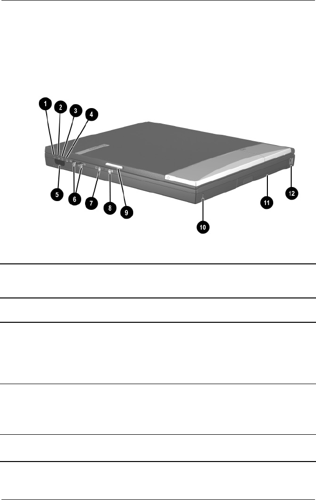
1.5 Notebook External Components
The external components on the front and right side of the
Evo Notebook N620c, N610c, and N600c are shown in Figure
1-2 and described in Table 1-5.
.
Figure 1-2. Front and Right Side Components
Table 1-5
Front and Right Side Panel Components
Item Component Function
1 Power light On: Power is turned on.
Blinking: Notebook is in Standby. The power
light also blinks if a battery pack that is the
only available power source reaches a
low-battery condition.
2 Battery light On: A battery pack is charging.
Blinking: A battery pack that is the only
available power source has reached a
low-battery condition.
3 Drive activity light Turns on when the hard drive, CD-, or
DVD-ROM drive is accessed.

Product Description
Maintenance and Service Guide 1–31
4 Media Bay light Turns on when the diskette drive in the
Media Bay or the optional external diskette
drive is accessed.
5 Infrared port Links to another IrDA-compliant device for
wireless communication.
6 Volume control buttons Adjust the volume of the stereo speakers.
7 Stereo line-out/
headphone jack
Connects stereo speakers, headphones,
headset, or television audio.
8 Mono microphone jack Connects a mono microphone, disabling the
built-in microphone.
9 Display release latch Opens the notebook.
10 Security cable slot Attaches an optional security cable to the
notebook.
11 Media Bay Accepts a diskette drive, CD- or DVD-ROM
drive, or secondary battery pack.
12 RJ-11 jack (internal
modem models only)
Connects the modem cable to an internal
modem. A modem cable is included with
internal modem models.
Table 1-5
Front and Right Side Panel Components
(Continued)
Item Component Function
1–32 Maintenance and Service Guide
Product Description
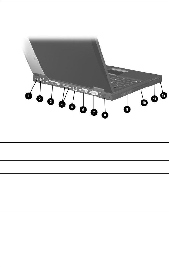
The Evo Notebook N620c, N610c, and N600c right side and rear
panel components are shown in Figure 1-3 and described in
Table 1-6.
Figure 1-3. Right Side and Rear Panel Components—
Evo Notebook N610c
Table 1-6
Right Side and Rear Panel Components
Item Component Function
1 DC power jack Connects any one of the following:
■AC adapter
■Optional automobile power
adapter/charger
■Optional aircraft power adapter
2 Keyboard/mouse
connector
Connects an external keyboard or
PS/2-compatible external mouse. To
connect a keyboard and a mouse at the
same time, use an optional Y-adapter.

Product Description
Maintenance and Service Guide 1–33
3 Parallel connector Connects a parallel device.
4 USB connectors (2) Connect USB devices.
5RJ-45 jack
(network models only)
Connects the network cable. A network
cable is not included with the notebook.
6 Serial connector Connects a serial device.
7 External monitor
connector
Connects an external monitor or overhead
projector.
8 S-Video connector Connects a television, VCR, camcorder, or
overhead projector.
9 Vent Allows airflow to cool internal components.
ÄTo prevent damage, the notebook
shuts down if an overheating
condition occurs. Do not block the
cooling vent. Avoid placing the
notebook on a blanket, rug, or other
flexible surface that may cover the
vent area.
10 Hard drive Supports the removable primary hard drive.
11 PC Card slots Support a 32-bit (CardBus) or 16-bit
PC Card.
12 PC Card eject buttons Eject a PC Card from a PC Card slot.
Table 1-6
Right Side and Rear Panel Components
(Continued)
Item Component Function
1–34 Maintenance and Service Guide
Product Description
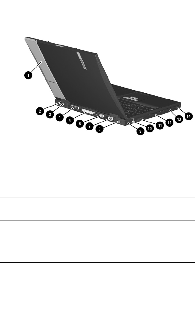
The Evo Notebook N600c right side and rear panel components
are shown in Figure 1-4 and described in Table 1-7.
Figure 1-4. Right Side and Rear Panel Components—
Evo Notebook N600c
Table 1-7
Right Side and Rear Panel Components
Item Component Function
1 MultiPort Connects wireless communication devices,
such as an optional Bluetooth or 802.11b
MultiPort module, and other options.
2 DC power jack Connects any one of the following:
■AC adapter
■Optional automobile power
adapter/charger
■Optional aircraft power adapter

Product Description
Maintenance and Service Guide 1–35
3 Keyboard/mouse
connector
Connects an external keyboard or
PS/2-compatible external mouse. To
connect a keyboard and a mouse at the
same time, use an optional Y-adapter.
4 Parallel connector Connects a parallel device.
5 Docking connector Connects the computer to the optional
expansion base, convenience base, or port
replicator.
6 Serial connector Connects a serial device.
7 External monitor
connector
Connects an external monitor or overhead
projector.
8 S-Video connector Connects a television, VCR, camcorder, or
overhead projector.
9RJ-45 jack (network
models only)
Connects the network cable. A network
cable is not included with the computer.
10 USB connectors (2) Connect USB devices.
11 Vent Allows airflow to cool internal components.
ÄTo prevent damage, the notebook
shuts down if an overheating
condition occurs. Do not block the
cooling vent. Avoid placing the
notebook on a blanket, rug, or other
flexible surface that may cover the
vent area.
12 Hard drive Supports the removable primary hard drive.
13 PC Card slots Support 32-bit (CardBus) or 16-bit PC
Cards.
14 PC Card eject buttons Eject PC Cards from the PC Card slots.
Table 1-7
Right Side and Rear Panel Components
(Continued)
Item Component Function
1–36 Maintenance and Service Guide
Product Description
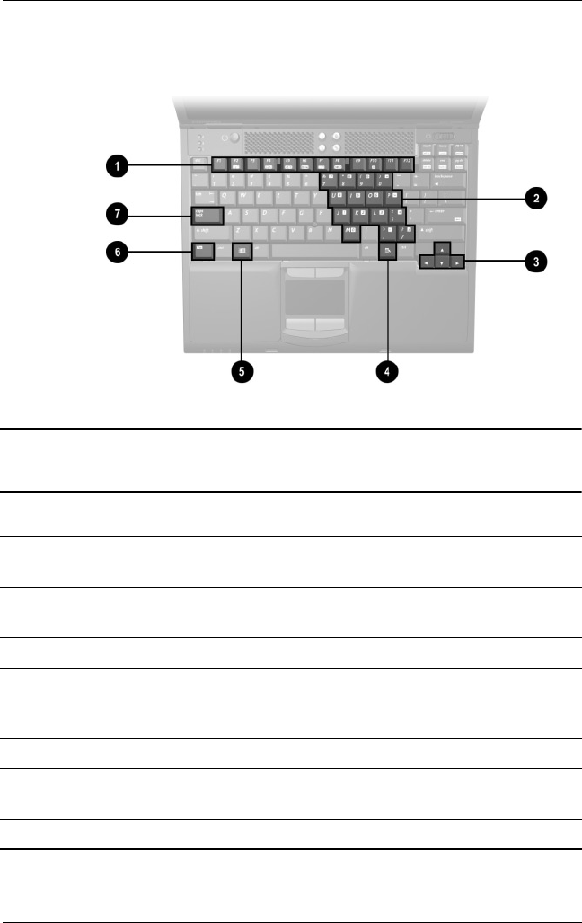
The keyboard components of the Evo Notebook N620c, N610c,
and N600c are shown in Figure 1-5 and described in Table 1-8.
Figure 1-5. Keyboard Components
Table 1-8
Keyboard Components
Item Component Function
1F1 through F12
function keys
Perform preset functions.
2 Embedded numeric
keypad
Converts keys to a numeric keypad.
3 Cursor control keys Move the cursor around the screen.
4 Windows
application key
Displays a menu when using a Microsoft
application. The menu is the same one that is
displayed by pressing the right mouse button.
5 Windows logo key Displays the Windows Start menu.
6Fn key Used with hotkeys to perform preset hotkey
functions.
7 Caps lock key Turns on the caps lock function.
Product Description
Maintenance and Service Guide 1–37
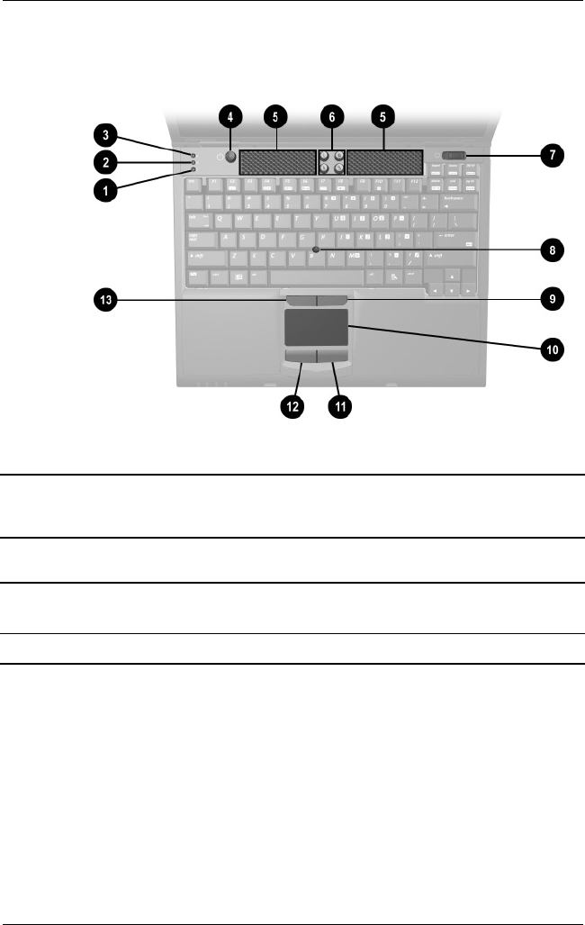
The components on the top of the Evo Notebook N620c, N610c,
and N600c are shown in Figure 1-6 and described in Table 1-9.
Figure 1-6. Top Components
Table 1-9
Top Components
Item Component Function
1 Num lock light On: Num lock is on and the embedded
numeric keypad is enabled.
2 Scroll lock light On: Scroll is on.

1–38 Maintenance and Service Guide
Product Description
3 Caps lock light On: Caps lock is on.
4 Standby button Turns on the notebook if it is off.
Initiates and exits Standby.
When pressed with the Fn key, initiates
Hibernation.
5 Stereo speakers (2) Produce stereo sound.
6 Easy Access buttons (4) Provide quick access to the Internet. Refer
to the
Hardware Guide
that ships with the
notebook for information about these
buttons.
7 Power switch Turns on the notebook. To turn off the
notebook, use the operating system
Shut Down command.
8 Pointing stick Moves the mouse cursor.
9 Right pointing stick
button
Functions like the right mouse button on an
external mouse.
10 TouchPad Moves the mouse cursor.
11 Right TouchPad button Functions like the right mouse button on an
external mouse.
12 Left TouchPad button Functions like the left mouse button on an
external mouse.
13 Left pointing stick button Functions like the left mouse button on an
external mouse.
Table 1-9
Top Components
(Continued)
Item Component Function
Product Description
Maintenance and Service Guide 1–39
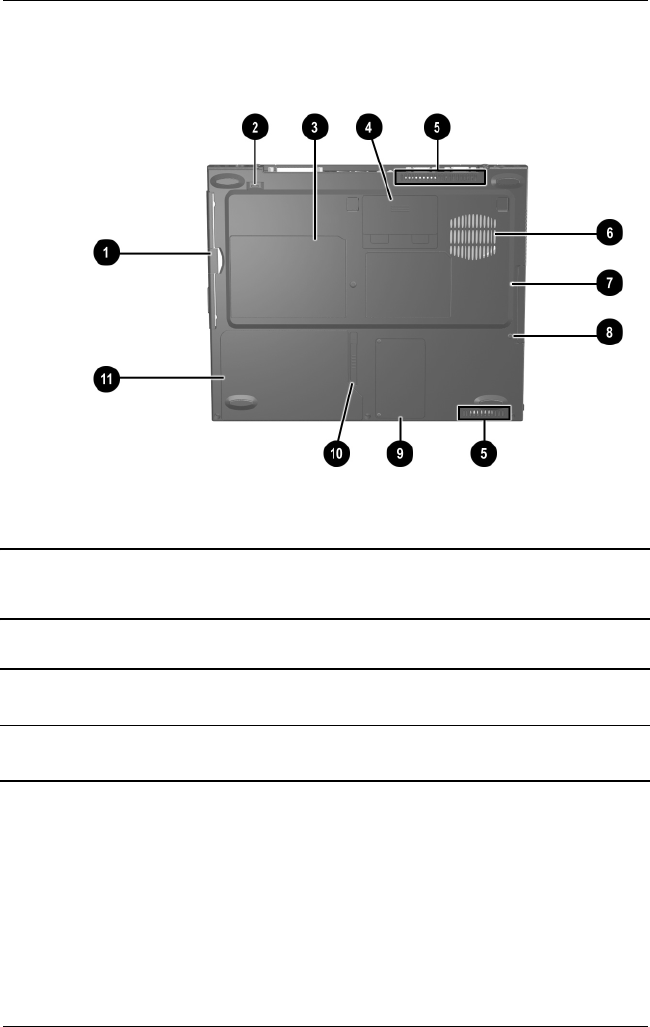
The Evo Notebook N620c and N610c bottom components are
shown in Figure 1-7 and described in Table 1-10.
Figure 1-7. Bottom Components—Evo Notebook N620c
and N610c
Table 1-10
Bottom Components
Item Component Function
1 Media Bay Accepts a diskette drive, CD- or DVD-ROM
drive, or secondary battery pack.
2 Media Bay release latch Releases the Media Bay device from the
connector.

1–40 Maintenance and Service Guide
Product Description
3 Serial number Identifies the notebook; needed when you
call Compaq customer support.
4 Docking connector Connects the notebook to the optional
expansion base, convenience base, or port
replicator.
5 Air vents (2) Allow airflow to cool internal components.
6 Fan Provides airflow to cool internal
components.
7 Hard drive Supports the removable primary hard drive.
8 Hard drive security
screw
Secures the hard drive.
9 Mini PCI compartment
cover
Covers the memory expansion
compartment that contains two memory
expansion slots for memory expansion
boards.
10 Battery release latch Releases the battery pack from the battery
compartment.
11 Battery compartment Holds the battery pack.
Table 1-10
Bottom Components
(Continued)
Item Component Function
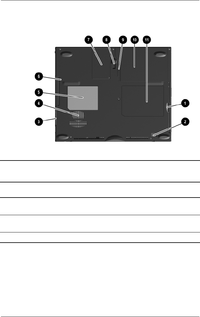
Product Description
Maintenance and Service Guide 1–41
The Evo Notebook N600c bottom components are shown in
Figure 1-8 and described in Table 1-11.
Figure 1-8. Bottom Components—Evo Notebook N600c
Table 1-11
Bottom Components
Item Component Function
1 Media Bay Accepts a diskette drive, optical drive, or
secondary battery pack.
2 Media Bay release latch Releases the Media Bay device from the
connector.
3 Vent Allows airflow to cool internal components.

1–42 Maintenance and Service Guide
Product Description
4 Fan Provides airflow to cool internal
components.
5 Certificate of
Authenticity label
Contains the Product Key, which may need
to be entered before using some Windows
operating systems.
6 Hard drive security
screw
Secures the hard drive.
7 Memory expansion
compartment cover
Covers the memory expansion
compartment that contains two memory
expansion slots for memory expansion
boards.
8 Docking recess latch Secures the computer to an optional
expansion base, convenience base, or port
replicator.
9 Battery release latch Releases the battery pack from the battery
compartment.
10 Battery compartment Holds the battery pack.
11 Serial number Identifies the computer; needed when you
call Compaq customer support.
Table 1-11
Bottom Components
(Continued)
Item Component Function

Product Description
Maintenance and Service Guide 1–43
1.6 Design Overview
This section presents a design overview of key parts and features
of the notebook. Refer to Chapter 3, “Illustrated Parts Catalog,”
to identify replacement parts, and Chapter 5, “Removal and
Replacement Procedures,” for disassembly steps. The system
board provides the following device connections:
■Memory expansion board
■Hard drive
■Display
■Keyboard/TouchPad or pointing stick
■Audio
■Intel Pentium 4 and Pentium III processors
■Fan
■PC Card
■Modem or modem/NIC
The notebook uses an electrical fan for ventilation. The fan is
controlled by a temperature sensor and is designed to turn on
automatically when high temperature conditions exist. These
conditions are affected by high external temperatures, system
power consumption, power management/battery conservation
configurations, battery fast charging, and software applications.
Exhaust air is displaced through the ventilation grill located on
the left side of the notebook.
ÄCAUTION: To properly ventilate the notebook, allow at least a
7.6-cm (3-inch) clearance on the left and right sides of the
notebook.

Maintenance and Service Guide 2–1
2
Troubleshooting
ÅWARNING: Only authorized technicians trained by Compaq should
repair this equipment. All troubleshooting and repair procedures
are detailed to allow only subassembly/module level repair.
Because of the complexity of the individual boards and
subassemblies, no one should attempt to make repairs at the
component level or make modifications to any printed wiring board.
Improper repairs can create a safety hazard. Any indication of
component replacement or printed wiring board modification may
void any warranty or exchange allowances.
2.1 Computer Setup and Diagnostics
Utilities
Selecting Computer Setup or Compaq
Diagnostics
The computer features two Compaq system management utilities:
■Computer Setup—A system information and customization
utility that can be used even when your operating system is
not working or will not load. This utility includes settings that
are not available in Windows.

2–2 Maintenance and Service Guide
Troubleshooting
■Compaq Diagnostics—A system information and diagnostic
utility that is used within your Windows operating system.
Use this utility whenever possible to:
❏Display system information.
❏Test system components.
❏Troubleshoot a device configuration problem
in Windows 2000, Windows XP Professional, or
Windows XP Home.
Using Computer Setup
Information and settings in Computer Setup are accessed from
the File, Security, or Advanced menus:
1. Turn on or restart the computer. Press F10 while the
F10 = ROM Based Setup message is displayed in the
lower-left corner of the screen.
❏To change the language, press F2.
❏To view navigation information, press F1.
❏To return to the Computer Setup menu, press esc.
2. Select the File, Security, or Advanced menu.
3. To close Computer Setup and restart the computer:
❏Select File > Save Changes and Exit and press enter.
or
❏Select File > Ignore Changes and Exit and press enter.
4. When you are prompted to confirm your action, press F10.

Troubleshooting
Maintenance and Service Guide 2–3
Selecting from the File Menu
Table 2-1
File Menu
Select To Do This
System Information ■View identification information about the
computer, a docking base, and any battery
packs in the system.
■View specification information about the
processor, memory and cache size, and
system ROM.
Save to Floppy Save system configuration settings to a diskette.
Restore from Floppy Restore system configuration settings from a
diskette.
Restore Defaults Replace configuration settings in Computer
Setup with factory default settings. (Identification
information is retained.)
Ignore Changes and Exit Cancel changes entered during the current
session, then exit and restart the computer.
Save Changes and Exit Save changes entered during the current
session, then exit and restart the computer.

2–4 Maintenance and Service Guide
Troubleshooting
Selecting from the Security Menu
Table 2-2
Security Menu
Select To Do This
Setup Password Enter, change, or delete a setup password.
(The setup password is called an administrator
password in Compaq Computer Security, a
program accessed from the Windows Control
Panel.)
Power-on Password Enter, change, or delete a power-on password.
DriveLock Passwords Enable/disable DriveLock; change a DriveLock
User or Master password.
✎Drive Lock Settings are accessible only
when you enter Computer Setup by
turning on (not restarting) the computer.
Password Options
Password options can be
selected only when a
power-on password has
been set.
Enable/disable:
■QuickLock
■QuickLock on Standby
■QuickBlank
✎To enable QuickLock on Standby or
QuickBlank, you must first enable
QuickLock.
Device Security Enable/disable:
■Ports or diskette drives*
■Diskette write*
■CD-ROM or diskette startup
✎Settings for a DVD-ROM can be
entered in the CD-ROM field.
System IDs Enter identification numbers for the computer, a
docking base, and all battery packs in the
system.
*Not applicable to SuperDisk LS-120 drives.

Troubleshooting
Maintenance and Service Guide 2–5
Selecting from the Advanced Menu
Table 2-3
Advanced Menu
Select To Do This
Language (or press F2) Change the Computer Setup language.
Boot Options Enable/disable:
■QuickBoot, which starts the computer more
quickly by eliminating some startup tests.
(If you suspect a memory failure and want to
test memory automatically during startup,
disable QuickBoot.)
■MultiBoot, which sets a startup sequence
that can include most bootable devices and
media in the system.
Device Options ■Enable/disable the embedded numeric
keypad at startup.
■Enable/disable multiple standard pointing
devices at startup. (To set the computer to
support only a single, usually nonstandard,
pointing device at startup, select Disable.)
■Enable/disable USB legacy support for a
USB keyboard. (When USB legacy support
is enabled, the keyboard works even when a
Windows operating system is not loaded.)
■Set an optional external monitor or overhead
projector connected to a video card in a
docking base as the primary device. (When
the computer display is set as secondary,
the computer must be shut down before
undocking from a docking base.)

2–6 Maintenance and Service Guide
Troubleshooting
Device Options
(continued)
■Change the parallel port mode from
Enhanced Parallel Port (EPP, the default
setting) to standard, bidirectional, EPP or
Enhanced Capabilities Port (ECP).
■Set video-out mode to NTSC (default), PAL,
NTSC-J, or PAL-M.*
■Enable/disable all settings in the SpeedStep
window. (When Disable is selected, the
computer runs in Battery Optimized mode.)
■Specify how the computer recognizes
multiple identical docking bases that are
identically equipped. (Select Disable to
recognize the docking bases as a single
docking base; select Enable to recognize
the docking bases individually, by serial
number.)
■Enable/disable the reporting of the
processor serial number by the processor
to the software.
HDD Self Test Options Run a quick comprehensive self test on hard
drives in the system that support the test
features.
* Video modes vary even within regions. However, NTSC is common in
North America; PAL, in Europe, Africa, and the Middle East; NTSC-J, in
Japan; and PAL-M, in Brazil. Other South and Central American regions
may use NTSC, PAL, or PAL-M.
Table 2-3
Advanced Menu
(Continued)
Select To Do This

Troubleshooting
Maintenance and Service Guide 2–7
2.2 Using Compaq Diagnostics
When you access Compaq Diagnostics, a scan of all system
components is displayed on the screen before the Compaq
Diagnostics window opens.
You can display more or less information from anywhere within
Compaq Diagnostics by selecting Level on the menu bar.
Compaq Diagnostics is designed to test Compaq components.
If non-Compaq components are tested, the results may be
inconclusive.
Obtaining, Saving, or Printing
Configuration Information
1. Access Compaq Diagnostics by selecting Start > Settings >
Control Panel > Compaq Diagnostics.
2. Select Categories, then select a category from the
drop-down list.
❏To save the information, select File > Save As.
❏To print the information, select File > Print.
3. To close Compaq Diagnostics, select File > Exit.

2–8 Maintenance and Service Guide
Troubleshooting
Obtaining, Saving, or Printing Diagnostic
Test Information
1. Access Compaq Diagnostics by selecting Start > Settings >
Control Panel > Compaq Diagnostics.
2. Select the Test tab.
3. In the scroll box, select the category or device you want
to test.
4. Select a test type:
❏Quick Test—Runs a quick, general test on each device in
a selected category.
❏Complete Test—Performs maximum testing on each
device in a selected category.
❏Custom Test—Performs maximum testing on a selected
device.
◆To run all tests for your selected device, click
Check All.
◆To run only the tests you select, click Uncheck All,
then select the checkbox for each test you want
to run.

Troubleshooting
Maintenance and Service Guide 2–9
5. Select a test mode:
❏Interactive Mode—Provides maximum control over the
testing process. You determine whether the test was
passed or failed, and you may be prompted to insert or
remove devices.
❏Unattended Mode—Does not display prompts. If errors
are found, they are displayed when testing is complete.
6. Click Begin Testing.
7. Select a tab to view a test report:
❏Status tab—Summarizes the tests run, passed, and failed
during the current testing session.
❏Log tab—Lists tests run on the system, the number of
times each test has run, the number of errors found on
each test, and the total run time of each test.
❏Error tab—Lists all errors found in the computer with
their error codes.
8. Select a tab to save the report:
❏Log tab—Select Save.
❏Error tab—Select Save.
9. Select a tab to print the report:
❏Log tab—Select File > Save As, then print the file from
your folder.

2–10 Maintenance and Service Guide
Troubleshooting
2.3 Troubleshooting Flowcharts
Table 2-4
Troubleshooting Flowcharts Overview
Flowchart Description
2.1 Initial Troubleshooting
2.2 No Power, Part 1
2.3 No Power, Part 2
2.4 No Power, Part 3
2.5 No Power, Part 4
2.6 No Video, Part 1
2.7 No Video, Part 2
2.8 Nonfunctioning Docking Station
2.9 No Operating System (OS) Loading
2.10 No OS Loading From Hard Drive, Part 1
2.11 No OS Loading From Hard Drive, Part 2
2.12 No OS Loading From Hard Drive, Part 3
2.13 No OS Loading From Diskette Drive
2.14 No OS Loading From CD- or DVD-ROM Drive
2.15 No Audio, Part 1
2.16 No Audio, Part 2
2.17 Nonfunctioning Device
2.18 Nonfunctioning Keyboard
2.19 Nonfunctioning Pointing Device
2.20 No Network or Modem Connection
Troubleshooting
Maintenance and Service Guide 2–11
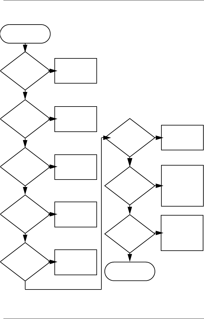
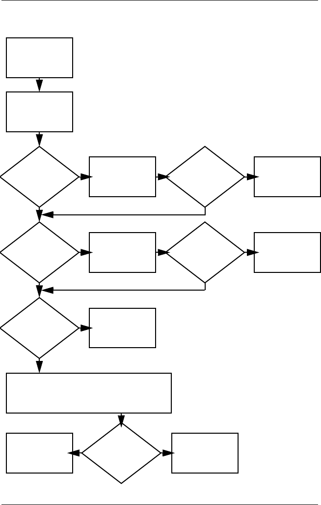
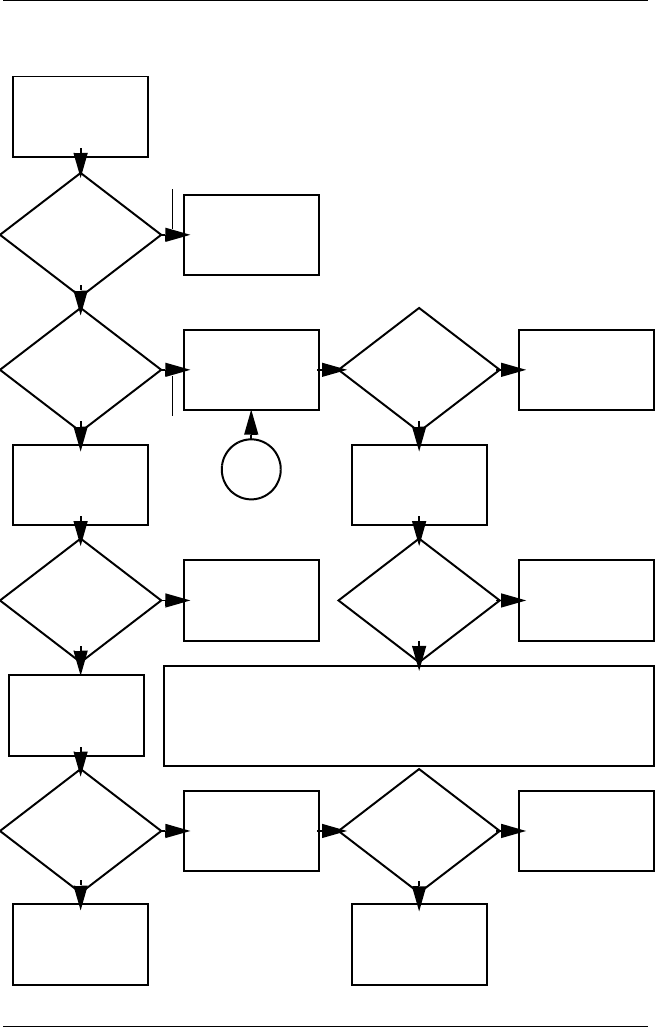
Flowchart 2.1 - Initial Troubleshooting
Connecting
to network
or modem?
Begin
troubleshooting.
Is there
power?
Is the OS
loading?
Is there video?
(no boot)
Is there
sound?
Beeps,
LEDs, or error
messages?
Keyboard/
pointing device
working?
Go to
Flowchart 2.17,
Nonfunctioning
Device.
Go to
Flowchart 2.2,
No Power, Part 1.
Go to
Flowchart 2.6,
No Video, Part 1.
All drives
working?
Y
Y
Y
Y
Y
Y
Y
Y
N
N
N
N
N
End
N
N
N
Go to
Flowchart 2.9,
No OS Loading.
Go to
Flowchart 2.15,
No Audio.
Go to
Flowchart 2.18,
Nonfunctioning
Keyboard,
or Flowchart 2.19,
Nonfunctioning
Pointing Device.
Check
LED board,
speaker
connections.
Go to
Flowchart 2.20,
No Network or
Modem
Connection.
2–12 Maintenance and Service Guide
Troubleshooting
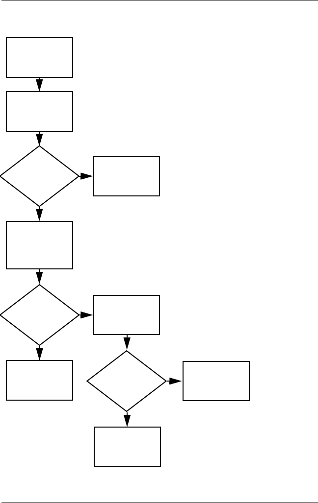
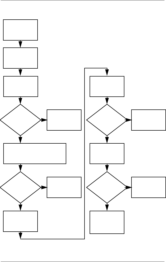
Flowchart 2.2 - No Power, Part 1
1. Reseat the power cables in the docking
station and at the AC outlet.
2. Ensure that the AC power source is active.
3. Ensure that the power strip is working.
Done
Remove from
docking station
(if applicable).
Power up
on battery
power?
Power up
on AC
power?
Power up
in docking
station?
Power up
on battery
power?
Power up
in docking
station?
Done
*Reset
power.
*Reset
power.
Power up
on AC
power?
N
Y
Y
N
N
Y
N
N
Y
Y
YN
*On some models there is a separate reset
button. On some models the computer may
be reset using the Standby switch and either
the lid switch or the main power switch.
Go to
Flowchart 2.4,
No Power,
Part 3.
Go to
Flowchart 2.3,
No Power,
Part 2.
Go to
Flowchart 2.8,
Nonfunctioning
Docking Station.
No power
(power LED
is off).
Troubleshooting
Maintenance and Service Guide 2–13
Flowchart 2.3 - No Power, Part 2
Continued from
Flowchart 2.2,
No Power, Part 1.
Visually check for
debris in battery
socket and clean if
necessary.
Done
N
Y
Power on?
Check battery
by recharging,
moving it to
another computer,
or replacing it.
Power on?
Done
Y
Replace
power supply
(if applicable).
N
Power on?
Done
Y
N
Go to
Flowchart 2.4,
No Power,
Part 3.
2–14 Maintenance and Service Guide
Troubleshooting
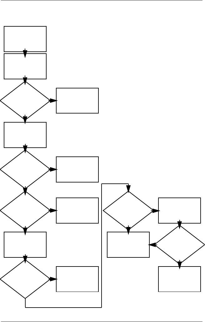
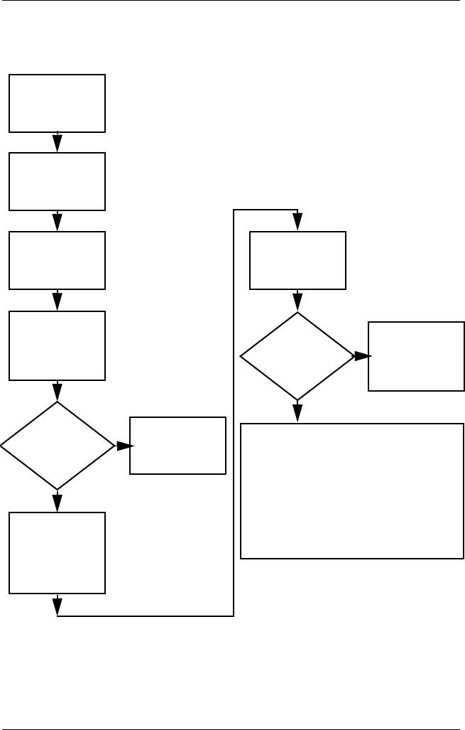
Flowchart 2.4 - No Power, Part 3
Continued from
Flowchart 2.3,
No Power, Part 2.
Reseat AC adapter
in computer and
at power source.
Internal or
external AC
adapter?
Done
Done
Done Done
Power on?
Power on?
Power on?
Plug directly
into AC outlet.
Power LED
on?
Power outlet
active? Try different
outlet.
Replace external
AC adapter.
Replace
power cord.
Y
N
Y
Y
Y
Y
N
N
N
N
External
Internal
Go to
Flowchart 2.5,
No Power,
Part 4.
Troubleshooting
Maintenance and Service Guide 2–15
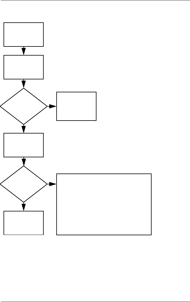
Flowchart 2.5 - No Power, Part 4
Y
N
Continued from
Flowchart 2.4,
No Power, Part 3.
Reseat loose
components and
boards and
replace
damaged items.
Open
computer.
Loose or
damaged
parts?
Y
Close
computer and
retest.
Power on?
Done
N
Replace the following items (if applicable).
Check computer operation after each
replacement:
1. Internal DC-DC converter*
2. Internal AC adapter
3. Processor board*
4. System board*
*Replace these items as a set to prevent
shorting out among components.
2–16 Maintenance and Service Guide
Troubleshooting
Flowchart 2.6 - No Video, Part 1
A
N
Stand-alone
or docking
station?
No video.
Replace the following one at a time. Test after each replacement.
1. Cable between notebook and computer display (if applicable)
2. Inverter board (if applicable)
3. Display
4. System board
Internal or
external
display*?
Adjust
brightness. Video OK? Done
Docking
station
Internal
Stand-alone
External
Adjust
brightness.
Video OK? Done
Y
Press lid
switch to ensure
operation.
Video OK? Done
Y
N
Video OK?
Done Done
N
Check for bent
pins on cable.
Try
another
display.
Internal and
external
video OK?
Replace
system
board.
YY
N
N
*To change from internal to
external display, use the hotkey
combination.
Y
Go to
Flowchart 2.7,
No Video, Part 2.
Troubleshooting
Maintenance and Service Guide 2–17
Flowchart 2.7 - No Video, Part 2
Y
N
Continued from
Flowchart 2.6,
No Video, Part 1.
Done
Video OK?
Adjust external
monitor display.
Adjust
display
brightness.
Video OK?
Video OK?
Done
Done
Check that notebook is properly
seated in docking station,
for bent pins on cable, and for
monitor connection.
Go to “A” in
Flowchart 2.6,
No Video, Part 1.
Check brightness
of external
monitor.
Try another
external
monitor.
Internal
and external
video OK?
Go to
Flowchart 2.8,
Nonfunctioning
Docking Station.
Y
Y
Y
N
N
N
Remove
notebook from
docking station,
if connected.
2–18 Maintenance and Service Guide
Troubleshooting
Flowchart 2.8 - Nonfunctioning Docking Station
(if applicable)
Y
N
Reseat power
cord in docking
station and
power outlet.
N
Replace the following docking station
components one at a time. Check
computer operation after each
replacement.
1. Power supply
2. I/O board
3. Backplane board
4. Switch box
5. Docking motor mechanism
Check voltage
setting on
docking station.
Reset monitor
cable connector at
docking station.
Reinstall
notebook into
docking station.
Docking
station
operating?
Docking
station
operating?
Remove
notebook, reseat
all internal parts,
and replace any
damaged items in
docking station.
Done
Done
Y
Nonfunctioning
docking station.
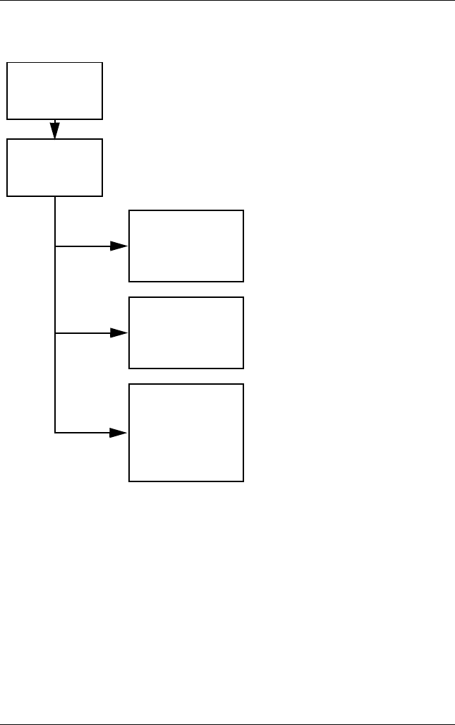
Troubleshooting
Maintenance and Service Guide 2–19
Flowchart 2.9 - No Operating System (OS) Loading
No OS loading
from hard drive,
go to Flowchart 2.10,
No OS Loading from
Hard Drive, Part 1.
Reseat power
cord in docking
station and
power outlet.
No OS
loading.*
*Before beginning troubleshooting, always
check cable connections, cable ends, and
drives for bent or damaged pins.
No OS loading
from CD- or
DVD-ROM drive,
go to Flowchart 2.14,
No OS Loading
from CD- or
DVD-ROM Drive.
No OS loading
from diskette drive,
go to Flowchart 2.13,
No OS Loading from
Diskette Drive.
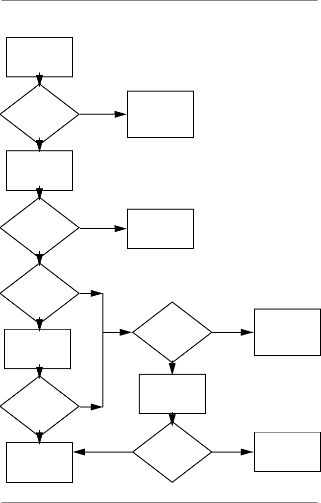
2–20 Maintenance and Service Guide
Troubleshooting
Flowchart 2.10 - No OS Loading from Hard Drive, Part 1
Go to
Flowchart 2.17,
Nonfunctioning
Device.
Y
Done
N
OS not
loading from
hard drive.
Nonsystem
disk message?
Go to
Flowchart 2.11,
No OS Loading
from Hard Drive,
Part 2.
Reseat
external
hard drive.
OS loading? Done
Boot
from
CD?
Go to
Flowchart 2.13,
No OS
Loading from
Diskette Drive.
Boot
from
hard drive?
Boot
from
diskette?
Change boot
priority through
the setup utility
and reboot.
Boot
from
hard drive?
Y
Y
Y
Y
Y
N
N
N
N
N
Check the setup
utility for correct
booting order.
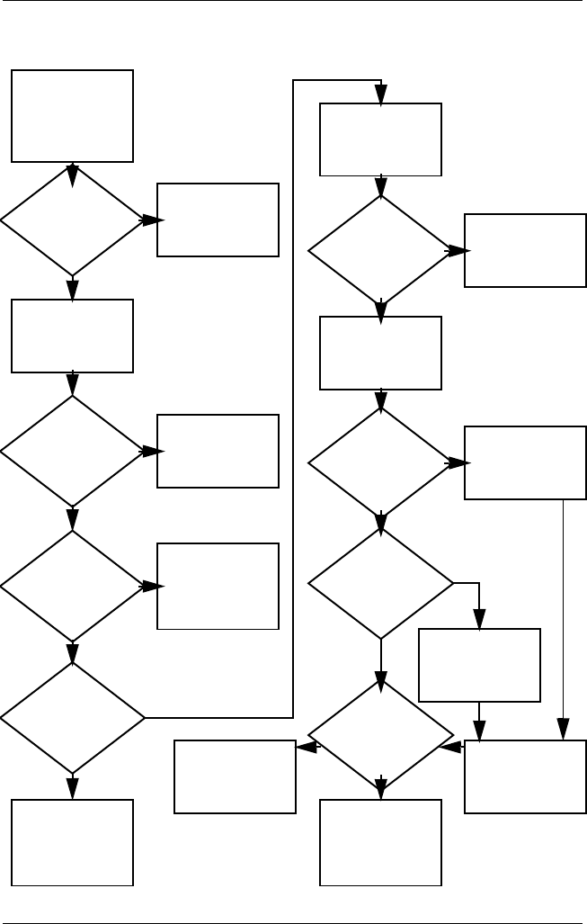
Troubleshooting
Maintenance and Service Guide 2–21
Flowchart 2.11 - No OS Loading from Hard Drive, Part 2
Continued from
Flowchart 2.10,
No OS Loading
from Hard Drive,
Part 1.
Reseat
hard drive.
Done
CD or
diskette in
drive?
1. Replace hard
drive.
2. Replace system
board.
Go to
Flowchart 2.13,
No OS Loading
from Diskette
Drive.
Load OS using
Restore CD
(if applicable).
Format hard drive
and bring to
a bootable
C:\ prompt.
Create partition,
then format hard
drive to bootable
C:\ prompt.
Boot
from diskette
drive?
Remove
diskette and
reboot.
Y
N
Boot
from
hard drive?
Y
N
Y
N
Hard drive
accessible?
Y
N
Hard drive
accessible? Done
Run FDISK.
Y
N
Hard drive
partitioned?
Hard drive
formatted?
Y
N
Y
N
Computer
booted?
Done
Y
N
Go to
Flowchart 2.12,
No OS Loading
from Hard Drive,
Part 3.
Go to
Flowchart 2.12,
No OS Loading
from Hard Drive,
Part 3.
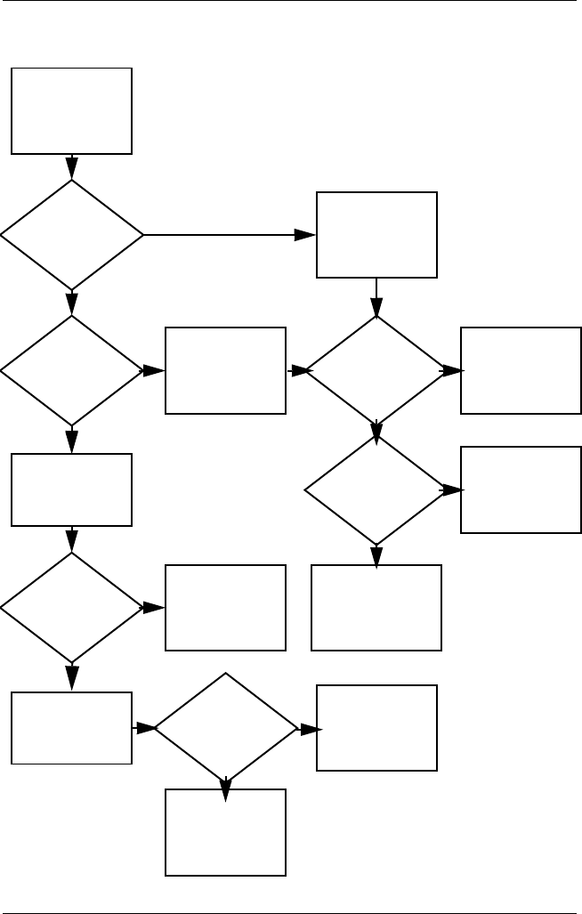
2–22 Maintenance and Service Guide
Troubleshooting
Flowchart 2.12 - No OS Loading from Hard Drive, Part 3
Y
System
files on hard
drive?
Continued from
Flowchart 2.11,
No OS Loading
from Hard Drive,
Part 2.
Clean virus. Done
N
Install OS
and reboot.
Virus
on hard
drive?
OS
loading from
hard drive?
Y
N
Y
N
Y
N
Diagnostics
on diskette?
Replace
hard drive.
Run diagnostics
and follow
recommendations.
Run SCANDISK
and check for
bad sectors.
Can bad
sectors
be fixed?
Replace
hard drive.
Y
N
Y
N
Fix bad
sectors. Boot from
hard drive?
Replace
hard drive.
Done
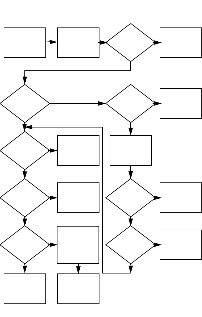
Troubleshooting
Maintenance and Service Guide 2–23
Flowchart 2.13 - No OS Loading from Diskette Drive
Done
Y
N
Reseat
diskette drive.
OS not loading
from
diskette drive.
Done
Y
Y
Y
Y
Y
Y
YN
N
NN
N
N
N
OS
loading?
Nonsystem
disk message?
Bootable
diskette
in drive?
Install bootable
diskette and
reboot computer.
Check diskette
for system files.
Try different
diskette.
1. Replace
diskette drive.
2. Replace system
board.
Nonsystem
disk error?
OS
loading?
Boot
from another
device?
Enable drive
and cold boot
computer.
Diskette
drive boot
order?
Change boot
priority using
the setup utility.
Go to
Flowchart 2.17,
Nonfunctioning
Device.
Diskette
drive enabled
in the setup
utility?
Go to
Flowchart 2.17,
Nonfunctioning
Device.
Clear CMOS.
Refer to
Section 1.3,
“Clearing a
Password,” for
instructions.
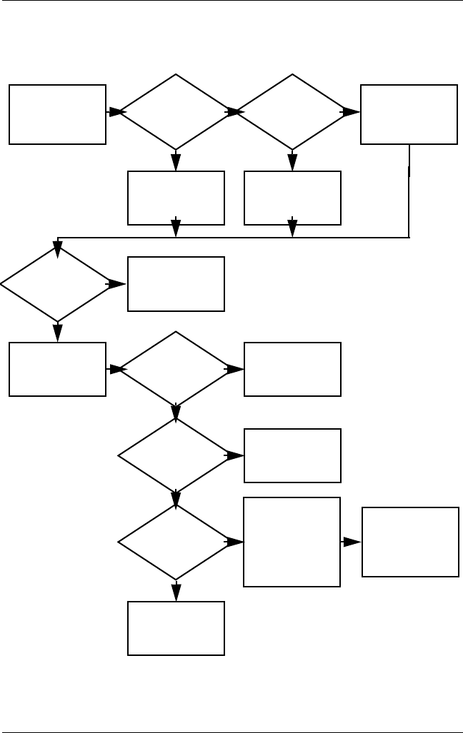
2–24 Maintenance and Service Guide
Troubleshooting
Flowchart 2.14 - No OS Loading from CD- or
DVD-ROM Drive
Clear CMOS.
Refer to
Section 1.3,
“Clearing a
Password,” for
instructions.
Y
Done
N
Bootable
disc in
drive?
Disc
in drive?
No OS
loading from
CD- or
DVD-ROM Drive.
Install bootable
disc and
reboot
computer.
Go to
Flowchart 2.17,
Nonfunctioning
Device.
Go to
Flowchart 2.17,
Nonfunctioning
Device.
Install
bootable disc.
Boots from
CD or DVD?
Boots from
CD or DVD?
Try another
bootable disc.
Booting
from another
device?
Booting
order
correct?
Correct boot
order using
the setup utility.
Done
Reseat
drive.
Y
Y
Y
Y
Y
N
N
N
N
N
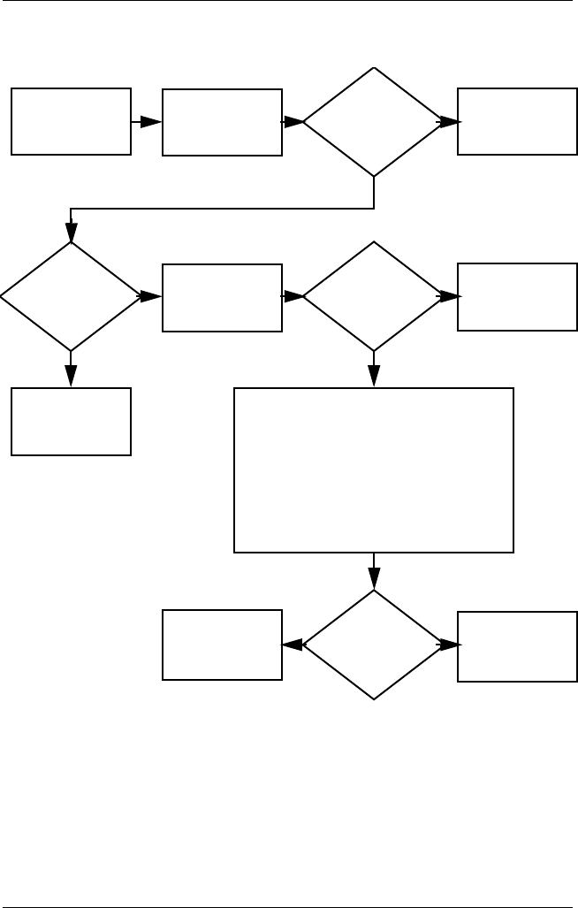
Troubleshooting
Maintenance and Service Guide 2–25
Flowchart 2.15 - No Audio, Part 1
No audio.
N
Notebook in
docking station
(if applicable)?
Internal
audio?
Audio? Done
Undock
Audio? Done
Turn up audio
internally or
externally.
Go to
Flowchart 2.16,
No Audio, Part 2.
Go to
Flowchart 2.16,
No Audio, Part 2.
Go to
Flowchart 2.17,
Nonfunctioning
Device.
Replace the following docking station
components one at a time as applicable.
Check after each change.
1. Reseat docking station audio cable.
2. Replace audio cable.
3. Replace speaker.
4. Replace docking station audio board.
5. Replace backplane board.
6. Replace I/O board.
Y
Y
Y
Y
N
N
N
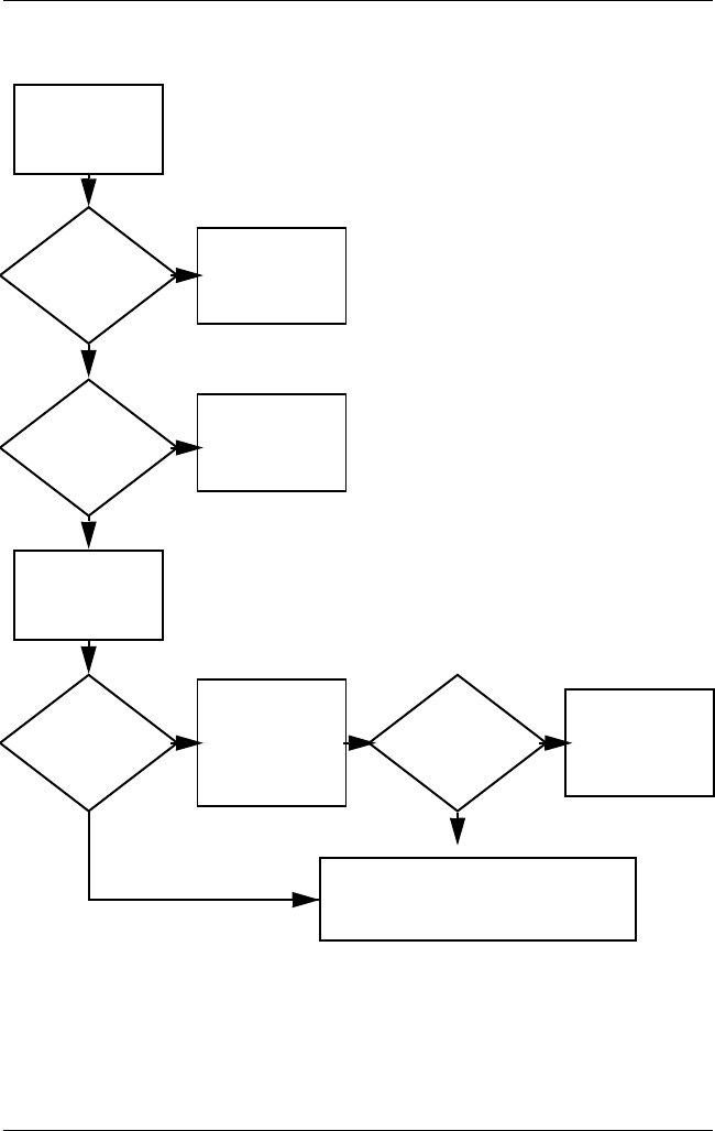
2–26 Maintenance and Service Guide
Troubleshooting
Flowchart 2.16 - No Audio, Part 2
YN
Continued from
Flowchart 2.15,
No Audio, Part 1.
Reload
audio drivers.
Audio
driver in OS
configured?
Audio?
Y
Y
YN
N
N
Correct
drivers for
application?
Connect to
external
speaker.
Load drivers and
set configuration
in OS.
Audio? Done
Replace audio
board and
speaker
connections in
notebook
(if applicable).
1. Replace internal speakers.
2. Replace audioboard(if applicable).
3. Replace system board.
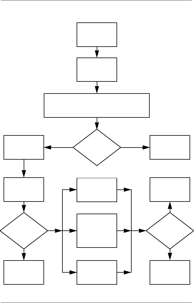
Troubleshooting
Maintenance and Service Guide 2–27
Flowchart 2.17 - Nonfunctioning Device
Done
Any physical
device detected?
Y
N
Unplug the nonfunctioning device
from the notebook and inspect cables
and plugs for bent or broken pins or
other damage.
Reseat
device.
Clear
CMOS.
Done
Fix or
replace
broken item.
Nonfunctioning
device.
Reattach device.
Close notebook,
plug in power,
and reboot.
Device
boots
properly?
Go to
Flowchart 2.9,
No OS Loading.
Device
boots
properly?
Possible bad
hard drive.
Replace drive.
Possible bad
diskette drive.
Replace drive.
Possible bad NIC.
Replace card. If
integrated NIC,
replace system
board.
Y
N
Y
N
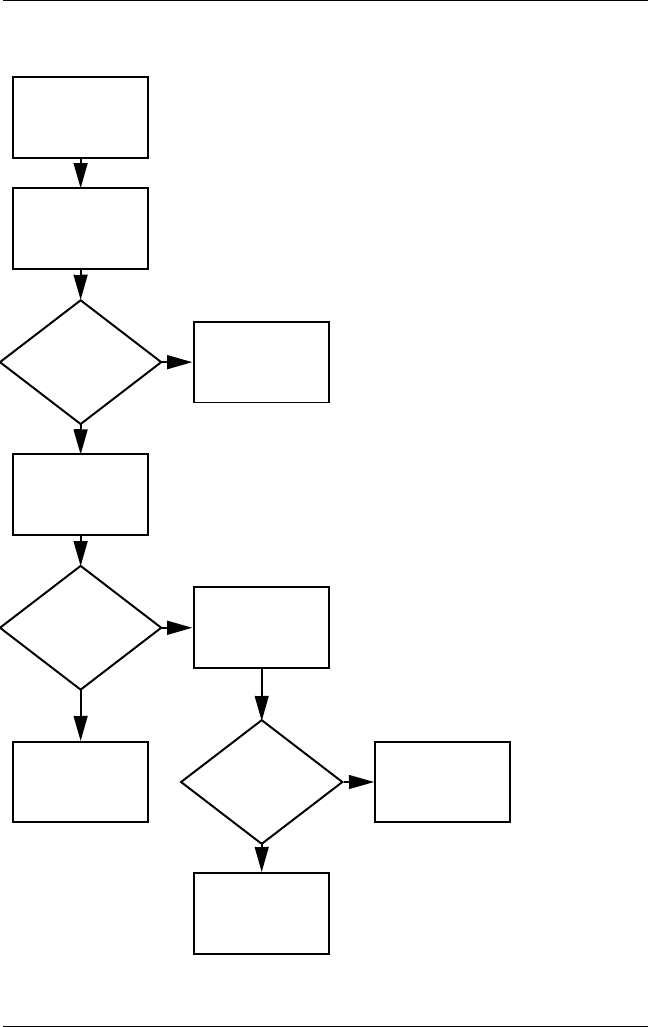
2–28 Maintenance and Service Guide
Troubleshooting
Flowchart 2.18 - Nonfunctioning Keyboard
Y
N
OK?
Keyboard
not operating
properly.
External
device
works?
Replace
system
board.
Replace
system
board.
Connect notebook
to good external
keyboard.
Reseat internal
keyboard
connector
(if applicable).
Replace internal
keyboard or
cable.
OK?
Y
N
Y
N
Done Done

Troubleshooting
Maintenance and Service Guide 2–29
Flowchart 2.19 - Nonfunctioning Pointing Device
Y
N
OK?
Pointing device
not operating
properly.
External
device
works?
Replace
system
board.
Replace
system
board.
Connect notebook
to good external
pointing device.
Reseat internal
pointing device
connector
(if applicable).
Replace internal
pointing device
or cable.
OK?
Y
N
Y
N
Done Done
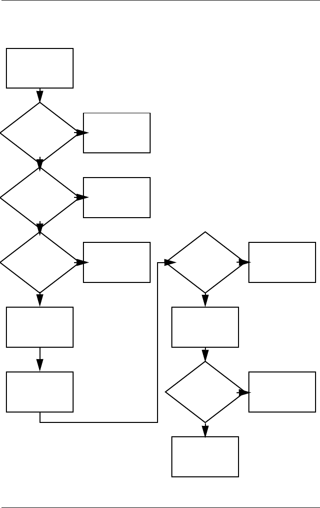
2–30 Maintenance and Service Guide
Troubleshooting
Flowchart 2.20 - No Network or Modem Connection
Y
Disconnect all
power from
the notebook
and open.
No network
or modem
connection.
N
Done
Digital
line?
Network
or modem jack
active?
Replace jack or
have jack
activated.
Connect
to nondigital
line.
NIC/modem
configured
in OS?
Reload
drivers and
reconfigure.
Reseat
NIC/modem
(if applicable).
Replace
NIC/modem
(if applicable).
Replace
system
board.
OK?
OK? Done
N
N
N
N
Y
Y
Y
Y
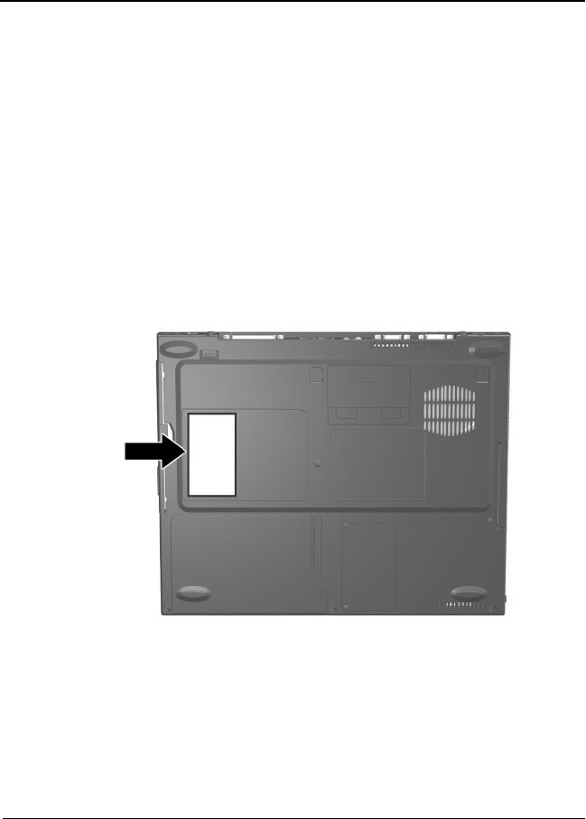
Maintenance and Service Guide 3–1
3
Illustrated Parts Catalog
This chapter provides an illustrated parts breakdown and a
reference for spare part numbers and option part numbers.
3.1 Serial Number Location
When ordering parts or requesting information, provide the
notebook serial number and model number located on the bottom
of the notebook (Figure 3-1).
Figure 3-1. Serial Number Location
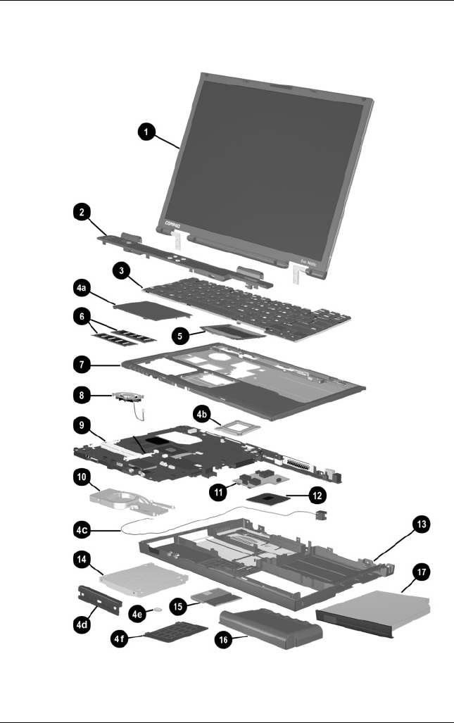
3–2 Maintenance and Service Guide
Illustrated Parts Catalog
3.2 Notebook System Major Components
Figure 3-2. Notebook System Major Components

Illustrated Parts Catalog
Maintenance and Service Guide 3–3
Table 3-1
Spare Parts: Notebook System Major Components
Item Description
Spare Part
Number
1Displays
For use with Evo Notebook N620c models only
14.1-inch, SXGA+, CTFT 319733-001
For use with Evo Notebook N610c models only:
14.1-inch, SXGA+, CTFT
14.1-inch, XGA, CTFT
291261-001
291262-001
For use with Evo Notebook N600c models only:
14.1-inch, SXGA+, CTFT
14.1-inch, XGA, CTFT
241433-001
241434-001
2Switch cover 241438-001
3Keyboard with pointing stick (for use with
Dual Stick models)
Arabic
Bosnia-
Herzegovina/
Croatia/
Slovenia/
Yugoslavia
Brazilian
Czech
Danish
European
French
French
Canadian
German
Greek
Hebrew
Hungarian
241427-171
241427-B41
241427-201
241427-221
241427-081
241427-021
241427-051
241427-121
241427-041
241427-151
241427-BB1
241427-211
International
Italian
Japanese
Korean
Latin American
Spanish
Norwegian
Portuguese
Russian
Slovakian
Spanish
Swedish/Finnish
Swiss
Taiwanese
Tu r k i s h
U.K. English
U.S. English
241427-002
241427-061
241427-291
241427-AD1
241427-161
241427-091
241427-131
241427-251
241427-231
241427-071
241427-101
241427-111
241427-AB1
241427-141
241427-031
241427-001

3–4 Maintenance and Service Guide
Illustrated Parts Catalog
Notebook System Major Components (continued)

Illustrated Parts Catalog
Maintenance and Service Guide 3–5
Table 3-1
Spare Parts: Notebook System Major Components
(Continued)
Item Description
Spare Part
Number
3Keyboard without pointing stick (for use with
TouchPad models)
Arabic
Bosnia-
Herzegovina/
Croatia/
Slovenia/
Yugoslavia
Brazilian
Czech
Danish
European
French
French
Canadian
German
Greek
Hebrew
Hungarian
241428-171
241428-B41
241428-201
241428-181
241428-221
241428-021
241428-051
241428-121
241428-041
241428-151
241428-BB1
241428-211
International
Italian
Japanese
Korean
Latin American
Spanish
Norwegian
Portuguese
Russian
Slovakian
Spanish
Swedish/Finnish
Swiss
Taiwanese
Tu r k i s h
U.K. English
U.S. English
241428-002
241428-061
241428-291
241428-AD1
241428-161
241428-091
241428-131
241428-251
241428-231
241428-071
241428-101
241428-111
241428-AB1
241428-141
241428-031
241428-001

3–6 Maintenance and Service Guide
Illustrated Parts Catalog
Notebook System Major Components (continued)

Illustrated Parts Catalog
Maintenance and Service Guide 3–7
Table 3-1
Spare Parts: Notebook System Major Components
(Continued)
Item Description
Spare Part
Number
Miscellaneous Plastics Kit 241439-001
4a
4b
4c
4d
4e
4f
Memory expansion compartment cover (on Evo Notebook N620c and
N610c models)
Mini PCI compartment cover (on Evo Notebook N600c models)
Processor bracket
Modem cable
Hard drive bezel
Disk cell RTC battery
Mini PCI compartment cover (on Evo Notebook N620c and
N610c models)
Memory expansion compartment cover (on Evo Notebook
N600c models)
Not illustrated:
MultiPort module cover
Notebook feet
PC Card slot space savers
RJ-11 cover
5TouchPad components
For use with Evo Notebook N620c models only:
TouchButton with pointing stick buttons
(for use with Dual Stick models)
319772-001
For use with Evo Notebook N610c models only:
TouchPad (for use with TouchPad models)
TouchButton with pointing stick buttons
(for use with Dual Stick models)
253658-001
252434-001
For use with Evo Notebook N600c models only:
TouchPad (for use with TouchPad models)
TouchButton with pointing stick buttons
(for use with Dual Stick models)
135227-001
159530-001
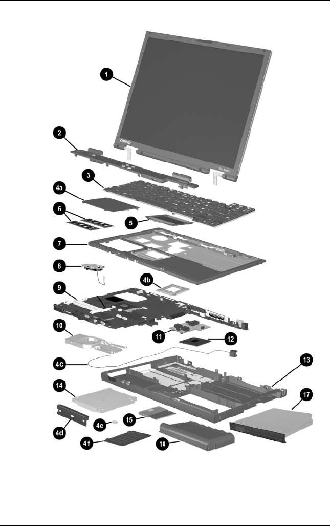
3–8 Maintenance and Service Guide
Illustrated Parts Catalog
Notebook System Major Components (continued)

Illustrated Parts Catalog
Maintenance and Service Guide 3–9
Table 3-1
Spare Parts: Notebook System Major Components
(Continued)
Item Description
Spare Part
Number
6Memory expansion boards
266 MHz, 2DM (for Evo Notebook N620c
models only)
1024 MB
768 MB
512 MB
384 MB
256 MB
301576-001
301575-001
301574-001
301572-001
301571-001
133 MHz (for Evo Notebook N610c models only)
512 MB
256 MB
128 MB
64 MB
238879-001
212683-001
212682-001
212681-001
100 MHz (for Evo Notebook N600c models only)
512 MB
256 MB
128 MB
280875-001
280874-001
280873-001
7Top covers
For use with Evo Notebook N620c and N610c
models only
For use with Evo Notebook N600c models only
291264-001
241436-001
8Fans
For use with Evo Notebook N620c and N610c
models only
For use with Evo Notebook N600c models only
291266-001
255528-001

3–10 Maintenance and Service Guide
Illustrated Parts Catalog
Notebook System Major Components (continued)

Illustrated Parts Catalog
Maintenance and Service Guide 3–11
Table 3-1
Spare Parts: Notebook System Major Components
(Continued)
Item Description
Spare Part
Number
9System boards
For use with Evo Notebook N620c models only
For use with Evo Notebook N610c models only
For use with Evo Notebook N600c models only:
Mobile Intel Pentium III processor 1.066 GHz-M
Mobile Intel Pentium III processor 866 MHz-M
319778-001
291581-001
241430-001
241432-001
10 Heat sink 303103-001
11 DC-DC converter boards
For use with Evo Notebook N620c models only
For use with Evo Notebook N610c models only
For use with Evo Notebook N600c models only
319635-001
291263-001
241435-001
12 Processors
For use only with Evo Notebook N620c models
Intel Pentium-M 1.6 GHz
Intel Pentium-M 1.5 GHz
Intel Pentium-M 1.4 GHz
Intel Pentium-M 1.3 GHz
319777-001
319776-001
319775-001
319774-001
For use only with Evo Notebook N610c models
Mobile Intel Pentium 4 2.0 GHz
Mobile Intel Pentium 4 1.8 GHz
Mobile Intel Pentium 4 1.7 GHz
Mobile Intel Pentium 4 1.6 GHz
303282-001
291269-001
291268-001
291267-001
Intel Celeron 1.5 GHz 309420-001
13 Base enclosures
For use with Evo Notebook N620c models only
For use with Evo Notebook N610c models only
For use with Evo Notebook N600c models only
310547-001
291265-001
241437-001

3–12 Maintenance and Service Guide
Illustrated Parts Catalog
Notebook System Major Components (continued)

Illustrated Parts Catalog
Maintenance and Service Guide 3–13
Table 3-1
Spare Parts: Notebook System Major Components
(Continued)
Item Description
Spare Part
Number
14 Hard drives
For use with Evo Notebook N620c models only:
60 GB, 5400 RPM
60 GB, 4200 RPM
40 GB, 5400 RPM
40 GB, 4200 RPM
309475-001
309474-001
309473-001
309472-001
For use with Evo Notebook N610c models only:
40 GB
30 GB
20 GB
265495-001
257660-001
235540-101
For use with Evo Notebook N600c models only:
30 GB
20 GB
15 GB
10 GB
217096-001
235421-001
241429-001
217094-001
15 Mini PCI communications boards
Type III mini PCI combination 56-Kbps modem/NIC
Type III mini PCI combination 56-Kbps modem/
3DES NIC
Type III mini PCI 56-Kbps modem
230338-001
230339-001
230337-001
16 Battery packs (6-cell, Li ion) 232633-001
and
301952-001

3–14 Maintenance and Service Guide
Illustrated Parts Catalog
Notebook System Major Components (continued)

Illustrated Parts Catalog
Maintenance and Service Guide 3–15
Table 3-1
Spare Parts: Notebook System Major Components
(Continued)
Item Description
Spare Part
Number
17 Media Bay devices
For use with all Evo Notebook N620c, N610c, and
N600c models:
Diskette drive
24X Max CD-ROM drive
8X Max CD-RW drive
8X Max DVD-ROM drive
DVD/CD-RW combination drive
2X Max SuperDisk LS120 drive
IOmega 250-MB ZIP drive
MultiBay battery pack, 6 cell
MultiBay battery pack, 3.2 ah
135233-001
228746-001
and
228746-001
153992-001
173949-001
238878-001
201274-001
218683-001
100680-001
280876-001
For use with Evo Notebook N620c and N610c
models only:
16X Max CD-RW drive
24X Max DVD/CD-RW combination drive
274419-001
274420-001
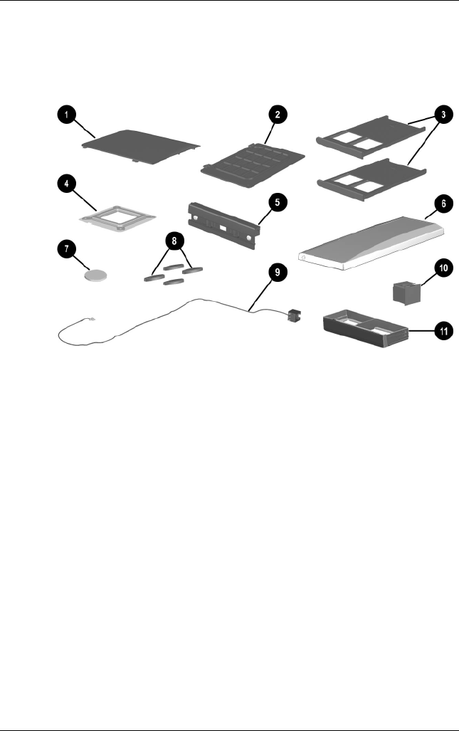
3–16 Maintenance and Service Guide
Illustrated Parts Catalog
3.3 Miscellaneous Plastics Kit
Components
Figure 3-3 Miscellaneous Plastics Kit Components

Illustrated Parts Catalog
Maintenance and Service Guide 3–17
Table 3-2
Miscellaneous Plastics Kit Components
Spare Part Number 241439-001
Item Description
1 Memory expansion compartment cover (Evo Notebook N620c and
N610c models)
Mini PCI compartment cover (Evo Notebook N600c models)
2 Mini PCI compartment cover (Evo Notebook N620c and
N610c models)
Memory expansion compartment cover (Evo Notebook N600c models)
3 PC Card slot space savers
4 Processor bracket
5 Hard drive bezel
6 MultiPort module cover
7 Disk cell RTC battery
8 Notebook feet
9 Modem cable
10 RJ-11 connector cover
11 Media Bay space saver
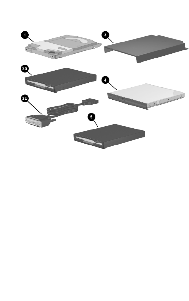
3–18 Maintenance and Service Guide
Illustrated Parts Catalog
3.4 Mass Storage Devices
Figure 3-4. Mass Storage Devices

Illustrated Parts Catalog
Maintenance and Service Guide 3–19
l
Table 3-3
Mass Storage Devices
Item Description
Spare Part
Number
1Hard drives
For use with Evo Notebook N620c models only:
60 GB, 5400 RPM
60 GB, 4200 RPM
40 GB, 5400 RPM
40 GB, 4200 RPM
309475-001
309474-001
309473-001
309472-001
For use with Evo Notebook N610c models only:
40 GB
30 GB
20 GB
265495-001
257660-001
235540-101
For use with Evo Notebook N600c models only:
30 GB
20 GB
15 GB
10 GB
217096-001
235421-001
241429-001
217094-001
2a
2b
Diskette drive
External diskette drive cable
135233-001
135232-001
3External Media Bay cradle
External Media Bay USB cradle
External Media Bay USB cradle cable
External Media Bay cradle AC adaptor
External Media Bay cradle plugs
218685-001
280879-001
287693-001
287694-001
287695-001
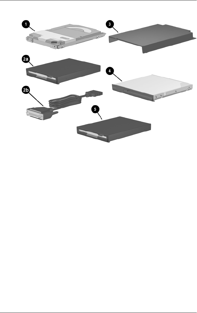
3–20 Maintenance and Service Guide
Illustrated Parts Catalog
Mass Storage Devices (continued)

Illustrated Parts Catalog
Maintenance and Service Guide 3–21
l
Table 3-3
Mass Storage Devices
(Continued)
Item Description
Spare Part
Number
4Optical drives
For use with all Evo Notebook N620c, N610c,
and N600c models:
Diskette drive
24X Max CD-ROM drive
8X Max CD-RW drive
8X Max DVD-ROM drive
DVD/CD-RW combination drive
2X Max SuperDisk LS120 drive
Iomega 250-MB ZIP drive
MultiBay battery pack, 6 cell
MultiBay battery pack, 3.2 ah
135233-001
228746-001
and
228746-001
153992-001
173949-001
238878-001
201274-001
218683-001
100680-001
280876-001
For use with Evo Notebook N620c and N610c
models only:
16X Max CD-RW drive
24X Max DVD/CD-RW combination drive
274419-001
274420-001
5Iomega 250-MB ZIP drive
2X Max SuperDisk LS120 drive
218683-001
201274-001

3–22 Maintenance and Service Guide
Illustrated Parts Catalog
3.5 Miscellaneous
Table 3-4
Spare Parts: Miscellaneous (not illustrated)
Description
Spare Part
Number
AC adaptors
90-Watt AC adapter power supply
65-Watt AC adapter power supply
50-Watt AC adapter power supply
239705-001
239704-001
120765-001
Bluetooth wireless communication MultiPort module 230336-001
Logo kit 304204-001
Modems
Type III mini PCI combination 56-Kbps modem/NIC
Type III mini PCI combination 56-Kbps modem/3DES NIC
Type III mini PCI 56-Kbps modem
230338-001
230339-001
230337-001
Modem adapters
Czech
German
Hungarian
Norwegian
Swiss
234963-221
236432-041
234963-211
234963-091
198294-111
Modem cable 234962-001
Modem cable adapters
Australian
Belgian
French
304398-011
304398-181
304398-051

Illustrated Parts Catalog
Maintenance and Service Guide 3–23
Power cord, black, 6 feet
Australian
Danish
European/Middle Eastern/African
Italian
Japanese
Korean
Swiss
U.K. English
U.S. English
246959-011
246959-081
246959-021
246959-061
246959-291
246959-AD1
246959-AG1
246959-031
246959-001
RJ-11 P55 adapters
Danish
Finnish
Italian
Swedish
316904-081
316904-351
316904-061
316904-101
RJ-11 PTT adapter (used in the United Kingdom) 158593-031
RJ-45 network cable 239049-001
Screw Kit (includes the following screws and bushing guides;
refer to Appendix C, “Screw Listing,” for more information on
screw specifications and usage)
241440-001
■To r x T8 M 2 × 7
■To r x T8 M 2 × 5
■7.0-mm bushing guide
■Phillips M1 × 6
■Phillips M2 × 6.5
Table 3-4
Spare Parts: Miscellaneous (not illustrated)
(Continued)
Description
Spare Part
Number

Maintenance and Service Guide 4–1
4
Removal and Replacement
Preliminaries
This chapter provides essential information for proper and safe
removal and replacement service.
4.1 Tools Required
You will need the following tools to complete the removal and
replacement procedures:
■Magnetic screwdriver
■Phillips P0 screwdriver
■7.0-mm socket wrench (for Evo Notebook N600c models)
■Tool kit (includes connector removal tool, loopback plugs,
and case utility tool)
4.2 Service Considerations
The following sections include some of the considerations that
you should keep in mind during disassembly and assembly
procedures.
✎As you remove each subassembly from the computer, place the
subassembly (and all accompanying screws) away from the work
area to prevent damage.

4–2 Maintenance and Service Guide
Removal and Replacement Preliminaries
Plastic Parts
Using excessive force during disassembly and reassembly can
damage plastic parts. Use care when handling the plastic parts.
Apply pressure only at the points designated in the maintenance
instructions.
Cables and Connectors
Cables must be handled with extreme care to avoid damage.
Apply only the tension required to unseat or seat the cables
during removal and insertion. Handle cables by the connector
whenever possible. In all cases, avoid bending, twisting, or
tearing cables. Ensure that cables are routed in such a way that
they cannot be caught or snagged by parts being removed or
replaced. Handle flex cables with extreme care; these cables tear
easily.
ÄCAUTION: When servicing the computer, ensure that cables are
placed in their proper locations during the reassembly process.
Improper cable placement can damage the computer.
4.3 Preventing Damage to
Removable Drives
Removable drives are fragile components that must be handled
with care. To prevent damage to the computer, damage to a
removable drive, or loss of information, observe the following
precautions:
■Before removing or inserting a hard drive, shut down the
computer. If you are unsure whether the computer is off or in
Hibernation, turn the computer on, then shut it down.
■Before removing a diskette drive or optical drive, ensure that
a diskette or disc is not in the drive. Ensure that the optical
drive tray is closed.

Removal and Replacement Preliminaries
Maintenance and Service Guide 4–3
■Before handling a drive, ensure that you are discharged of
static electricity. While handling a drive, avoid touching the
connector.
■Handle drives on surfaces that have at least one inch of
shock-proof foam.
■Avoid dropping drives from any height onto any surface.
■After removing a hard drive, CD-ROM drive, or a diskette
drive, place it in a static-proof bag.
■Avoid exposing a hard drive to products that have magnetic
fields, such as monitors or speakers.
■Avoid exposing a drive to temperature extremes or to liquids.
■If a drive must be mailed, place the drive in a bubble pack
mailer or other suitable form of protective packaging and
label the package “Fragile: Handle With Care.”
4.4 Preventing Electrostatic Damage
Many electronic components are sensitive to electrostatic
discharge (ESD). Circuitry design and structure determine the
degree of sensitivity. Networks built into many integrated circuits
provide some protection, but in many cases the discharge contains
enough power to alter device parameters or melt silicon junctions.
A sudden discharge of static electricity from a finger or other
conductor can destroy static-sensitive devices or microcircuitry.
Often the spark is neither felt nor heard, but damage occurs.
An electronic device exposed to electrostatic discharge may not
be affected at all and can work perfectly throughout a normal
cycle. Or the device may function normally for a while, then
degrade in the internal layers, reducing its life expectancy.

4–4 Maintenance and Service Guide
Removal and Replacement Preliminaries
4.5 Packaging and Transporting
Precautions
Use the following grounding precautions when packaging and
transporting equipment:
■To avoid hand contact, transport products in static-safe
containers, such as tubes, bags, or boxes.
■Protect all electrostatic-sensitive parts and assemblies with
conductive or approved containers or packaging.
■Keep electrostatic-sensitive parts in their containers until the
parts arrive at static-free workstations.
■Place items on a grounded surface before removing items
from their containers.
■Always be properly grounded when touching a sensitive
component or assembly.
■Store reusable electrostatic-sensitive parts from assemblies in
protective packaging or nonconductive foam.
■Use transporters and conveyers made of antistatic belts and
roller bushings. Ensure that mechanized equipment used for
moving materials is wired to ground and that proper materials
are selected to avoid static charging. When grounding is not
possible, use an ionizer to dissipate electric charges.
4.6 Workstation Precautions
Use the following grounding precautions at workstations:
■Cover the workstation with approved static-dissipative
material (refer to Table 4-2).
■Use a wrist strap connected to a properly grounded work
surface and use properly grounded tools and equipment.
■Use conductive field service tools, such as cutters,
screwdrivers, and vacuums.

Removal and Replacement Preliminaries
Maintenance and Service Guide 4–5
■When using fixtures that must directly contact dissipative
surfaces, only use fixtures made of static-safe materials.
■Keep the work area free of nonconductive materials, such as
ordinary plastic assembly aids and Styrofoam.
■Handle electrostatic-sensitive components, parts, and
assemblies by the case or PCM laminate. Handle these items
only at static-free workstations.
■Avoid contact with pins, leads, or circuitry.
■Turn off power and input signals before inserting or removing
connectors or test equipment.
4.7 Grounding Equipment and Methods
Grounding equipment must include either a wrist strap or a foot
strap at a grounded workstation.
■When seated, wear a wrist strap connected to a grounded
system. Wrist straps are flexible straps with a minimum
of one megohm ±10% resistance in the ground cords. To
provide proper ground, wear a strap snugly against the skin at
all times. On grounded mats with banana-plug connectors,
connect a wrist strap with alligator clips.
■When standing, use foot straps and a grounded floor mat.
Foot straps (heel, toe, or boot straps) can be used at standing
workstations and are compatible with most types of shoes
or boots. On conductive floors or dissipative floor mats, use
foot straps on both feet with a minimum of one-megohm
resistance between the operator and ground. To be effective,
the conductive strips must be worn in contact with the skin.

4–6 Maintenance and Service Guide
Removal and Replacement Preliminaries
Other grounding equipment recommended for use in preventing
electrostatic damage includes:
■Antistatic tape
■Antistatic smocks, aprons, and sleeve protectors
■Conductive bins and other assembly or soldering aids
■Nonconductive foam
■Conductive tabletop workstations with ground cords of
one-megohm resistance
■Static-dissipative tables or floor mats with hard ties to
the ground
■Field service kits
■Static awareness labels
■Material-handling packages
■Nonconductive plastic bags, tubes, or boxes
■Metal tote boxes
■Electrostatic voltage levels and protective materials

Removal and Replacement Preliminaries
Maintenance and Service Guide 4–7
Table 4-1 shows how humidity affects the electrostatic voltage
levels generated by different activities.
Table 4-2 lists the shielding protection provided by antistatic bags
and floor mats.
Table 4-1
Typical Electrostatic Voltage Levels
Relative Humidity
Event 10% 40% 55%
Walking across carpet 35,000 V 15,000 V 7,500 V
Walking across vinyl floor 12,000 V 5,000 V 3,000 V
Motions of bench worker 6,000 V 800 V 400 V
Removing DIPS from plastic tube 2,000 V 700 V 400 V
Removing DIPS from vinyl tray 11,500 V 4,000 V 2,000 V
Removing DIPS from Styrofoam 14,500 V 5,000 V 3,500 V
Removing bubble pack from PCB 26,500 V 20,000 V 7,000 V
Packing PCBs in foam-lined box 21,000 V 11,000 V 5,000 V
✎A product can be degraded by as little as 700 V.
Table 4-2
Static-Shielding Materials
Material Use Voltage Protection Level
Antistatic plastic Bags 1,500 V
Carbon-loaded plastic Floor mats 7,500 V
Metallized laminate Floor mats 5,000 V

Maintenance and Service Guide 5–1
5
Removal and Replacement
Procedures
This chapter provides removal and replacement procedures.
Both Phillips P0 and Torx T8 screws are removed during
disassembly. There are 38 screws and screwlocks, in seven
different sizes, that must be removed and replaced when servicing
the notebook. Make special note of each screw size and location
during removal and replacement.
Refer to Appendix C, “Screw Listing,” for detailed information
on screw sizes, locations, and usage.
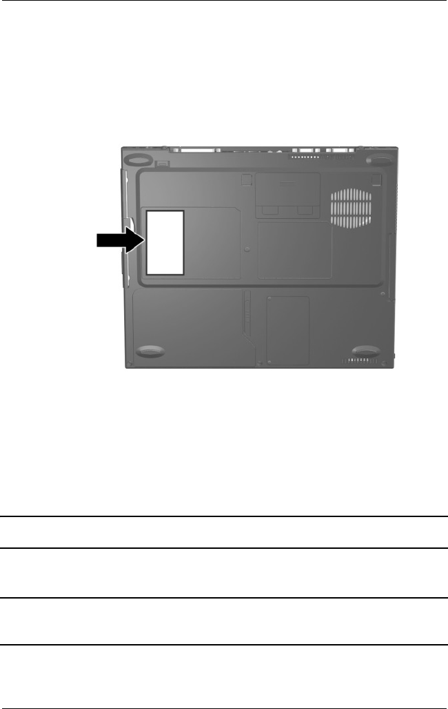
5–2 Maintenance and Service Guide
Removal and Replacement Procedures
5.1 Serial Number
Report the notebook serial number to Compaq when requesting
information or ordering spare parts. The serial number is located
on the bottom of the notebook (Figure 5-1).
Figure 5-1. Serial Number Location
5.2 Disassembly Sequence Chart
Use the chart below to determine the section number to be
referenced when removing notebook components.
Disassembly Sequence Chart
Section Description
# of Screws
Removed
5.3 Preparing the Notebook for Disassembly
Battery Pack 0

Removal and Replacement Procedures
Maintenance and Service Guide 5–3
Section Description
# of Screws
Removed
5.3 Preparing the Notebook for Disassembly
(Continued)
Media Bay Device 0
Hard Drive 1 to remove
hard drive
2 to remove
hard drive
bezel
5.4 Computer Feet 0
5.5 Mini PCI Communications Board 2
5.6 Disk Cell Real Time Clock (RTC) Battery 0
5.7 Keyboard 1
5.8 Memory Expansion 0
5.9 TouchPad 0
5.10 Switch Cover 2
5.11 Display 3
5.12 Top Cover 13
5.13 System Board 5
5.14 Fan 3
5.15 Heat Sink (Evo Notebook N620c and N610c
models only)
6
5.16 Processor (Evo Notebook N620c and N610c
models only)
0
5.17 DC-DC Converter Board 0
5.18 Modem Cable 0
Disassembly Sequence Chart
(Continued)

5–4 Maintenance and Service Guide
Removal and Replacement Procedures
5.3 Preparing the Notebook for
Disassembly
Perform the following steps before disassembling the notebook:
1. Turn off the notebook.
2. Disconnect the AC adapter and all external devices.
3. Remove the battery pack by following these steps:
a. Turn the notebook bottom side up with the front facing
forward.
Battery Pack, 6-cell, Li ion
Spare Part Number Information
Battery packs, 6-cell, Li ion 232633-001
and
301952-001
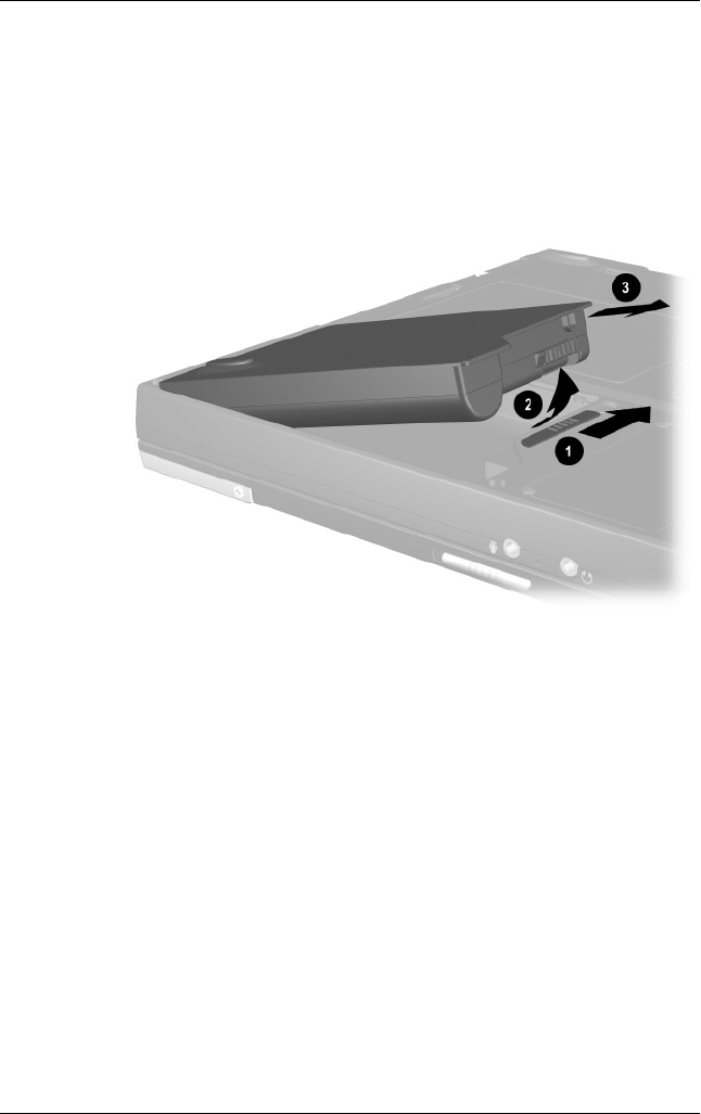
Removal and Replacement Procedures
Maintenance and Service Guide 5–5
b. Slide the battery release latch 1 toward the back of the
notebook (Figure 5-2).
c. Swing the right side of the battery pack up and to the
left 2.
d. Remove the battery pack 3.
Figure 5-2. Removing the Battery Pack
Reverse the preceding procedure to install the battery pack.

5–6 Maintenance and Service Guide
Removal and Replacement Procedures
Media Bay Devices
Spare Part Number Information
For use with all Evo Notebook N620c, N610c, and
N600c models:
Diskette drive
24X Max CD-ROM drive
8X Max CD-RW drive
8X Max DVD-ROM drive
DVD/CD-RW combination drive
2X Max SuperDisk LS120 drive
Iomega 250-MB ZIP drive
6-cell battery pack
135233-001
228746-001
and
228746-001
153992-001
173949-001
238878-001
201274-001
218683-001
100680-001
and
280876-001
For use with Evo Notebook N620c and N610c models only:
16X Max CD-RW drive
24X Max DVD/CD-RW combination drive
274419-001
274420-001
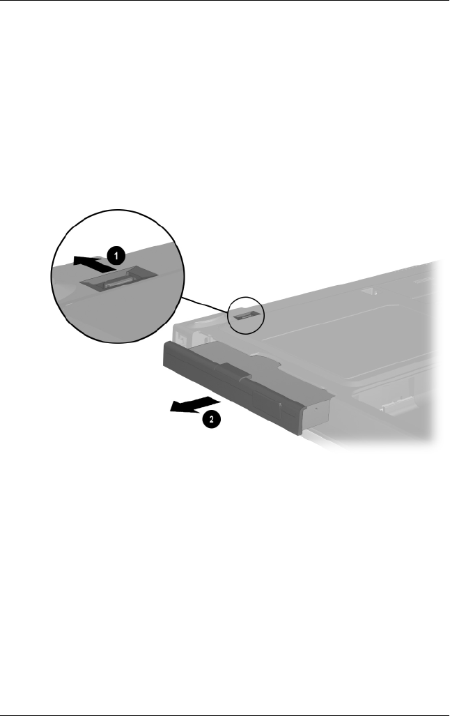
Removal and Replacement Procedures
Maintenance and Service Guide 5–7
4. Remove a Media Bay device by following these steps:
a. Turn the notebook bottom side up with the left side
facing forward.
b. Slide and hold the Media Bay release latch toward the
back of the notebook 1 (Figure 5-3).
c. Use the notch in the Media Bay device to slide the device
out of the Media Bay 2.
Figure 5-3. Removing a Media Bay Device
Reverse the preceding procedure to install the Media Bay device.

5–8 Maintenance and Service Guide
Removal and Replacement Procedures
5. Remove the hard drive by following these steps:
a. Turn the notebook bottom side up with the right side
facing forward.
Hard Drive
Spare Part Number Information
For use with Evo Notebook N620c models only:
60 GB, 5400 RPM
60 GB, 4200 RPM
40 GB, 5400 RPM
40 GB, 4200 RPM
309475-001
309474-001
309473-001
309472-001
For use with Evo Notebook N610c models only:
40 GB
30 GB
20 GB
265495-001
257660-001
235540-101
For use with Evo Notebook N600c models only:
30 GB
20 GB
15 GB
10 GB
217096-001
235421-001
241429-001
217094-001
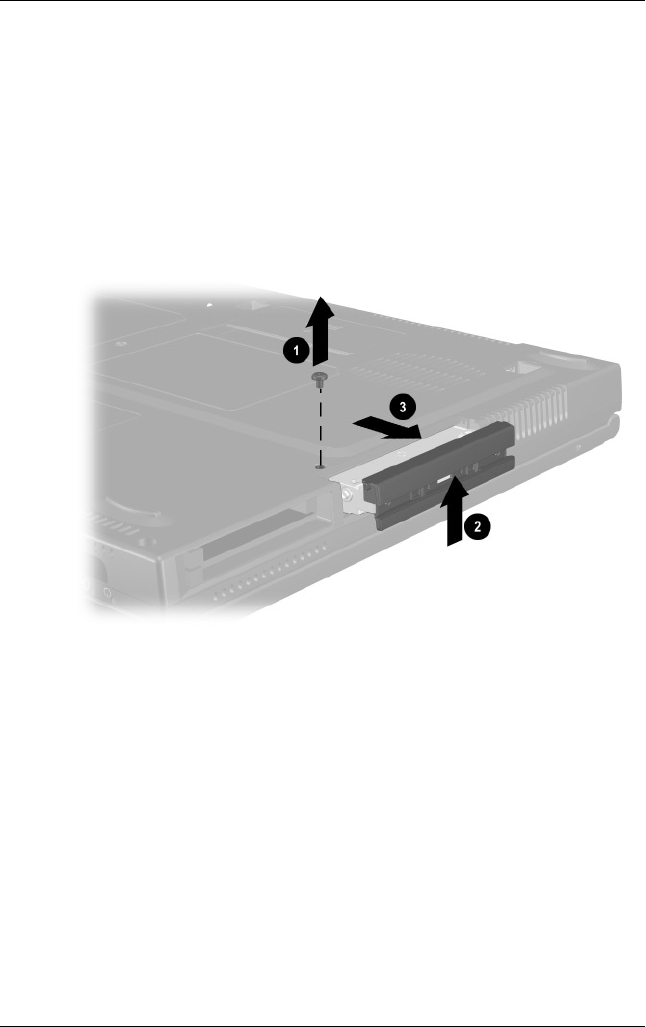
Removal and Replacement Procedures
Maintenance and Service Guide 5–9
b. Remove the PM2.5 × 2.5 hard drive retention screw 1
(Figure 5-4).
c. Separate the hard drive bezel 2.
d. Use the bezel to slide the hard drive forward 3 to unseat
the hard drive connector from the system board.
e. Remove the hard drive.
Figure 5-4. Removing the Hard Drive
Reverse the preceding procedure to install the hard drive.
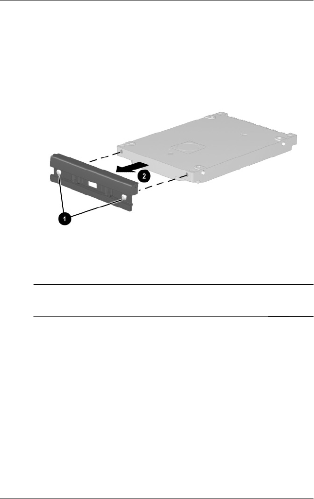
5–10 Maintenance and Service Guide
Removal and Replacement Procedures
6. Loosen the two PM1.5 × 3.5 screws 1 that secure the hard
drive bezel to the hard drive (Figure 5-5).
7. Remove the hard drive bezel from the hard drive 2.
Figure 5-5. Removing the Hard Drive Bezel
✎The hard drive bezel is included in the Miscellaneous Plastics Kit,
spare part number 241439-001.
Reverse the preceding procedure to install the hard drive bezel.
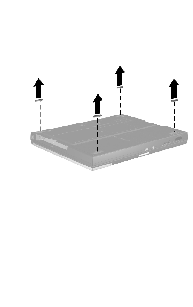
Removal and Replacement Procedures
Maintenance and Service Guide 5–11
5.4 Computer Feet
The notebook feet are adhesive-backed rubber pads. The
notebook feet are included in the Miscellaneous Plastics Kit
(spare part number 241439-001). Refer to Figure 5-6 for
notebook feet locations.
Figure 5-6. Replacing the Notebook Feet

5–12 Maintenance and Service Guide
Removal and Replacement Procedures
5.5 Mini PCI Communications Board
✎Compaq Evo Notebook N600c models contain a memory
expansion slot in this location. Refer to Section 5.8, steps 5 and 6,
for instructions on removing a memory expansion board. The
mini PCI compartment cover is included in the Miscellaneous
Plastics Kit (spare part number 241439-001).
1. Prepare the notebook for disassembly (Section 5.3).
2. Turn the notebook bottom side up with the front facing
forward.
Mini PCI Communications Board
Spare Part Number Information
Type III mini PCI combination 56-Kbps modem/NIC board
Type III mini PCI combination 56-Kbps/NIC/3DES board
Type III mini PCI 56-Kbps modem board
230338-001
230339-001
230337-001
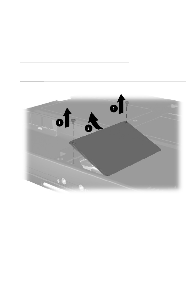
Removal and Replacement Procedures
Maintenance and Service Guide 5–13
3. Remove the two PM2.5 × 5.0 screws 1 that secure the mini
PCI compartment cover to the base enclosure (Figure 5-7).
4. Lift the left edge of the cover and swing it up and to the
right 2.
5. Remove the cover.
✎The mini PCI compartment cover is included in the
Miscellaneous Plastics Kit (spare part number 241439-001).
Figure 5-7. Removing the Mini PCI Compartment Cover
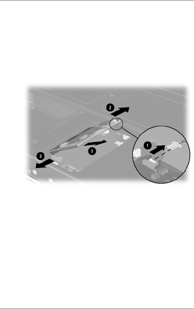
5–14 Maintenance and Service Guide
Removal and Replacement Procedures
6. Disconnect the modem cable from the mini PCI
communications board 1 (Figure 5-8).
7. Spread the retaining tabs 2 to release the mini
PCI communications board. The board tilts up at a
45-degree angle.
8. Remove the board by pulling it away from the connector
at a 45-degree angle 3.
Figure 5-8. Removing the Mini PCI Communications Board
Reverse the preceding procedure to install the mini PCI
communications board and mini PCI compartment cover.

Removal and Replacement Procedures
Maintenance and Service Guide 5–15
5.6 Disk Cell RTC Battery
✎The disk cell RTC battery on the Compaq Evo Notebook N600c
model is located under the memory expansion slot compartment
cover. Refer to Section 5.8 for instructions on removing the
memory expansion slot cover. The procedures used to remove an
RTC battery are the same for the Evo Notebook N620c, N610c,
and N600c. The disk cell RTC battery is included in the
Miscellaneous Plastics Kit (spare part number 241439-001).
1. Prepare the notebook for disassembly (Section 5.3).
2. Remove the mini PCI compartment cover (Section 5.5).
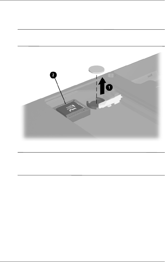
5–16 Maintenance and Service Guide
Removal and Replacement Procedures
3. Use a flat blade tool to remove the battery 1 from the socket
on the system board (Figure 5-9).
✎The system ROM 2 is also accessible when the mini PCI
compartment cover is removed.
Figure 5-9. Removing the Disk Cell RTC Battery
✎The notebook uses a CR1220 lithium disk cell battery. When
replacing the RTC battery, insert the battery with the “+” sign
facing up.

Removal and Replacement Procedures
Maintenance and Service Guide 5–17
5.7 Keyboard
Keyboard
Spare Part Number Information
Keyboard with Pointstick
Arabic
Bosnia-
Herzegovina/
Croatia/
Slovenia/
Yug o s l avia
Brazilian
Belgian
Czech
Danish
European
French
French Canadian
German
Greek
Hebrew
Hungarian
241427-171
241427-B41
241427-201
241427-181
241427-221
241427-081
241427-021
241427-051
241427-121
241427-041
241427-151
241427-BB1
241427-211
International
Italian
Japanese
Korean
Latin American Spanish
Norwegian
Portuguese
Russian
Slovakian
Spanish
Swedish/Finnish
Swiss
Taiwanese
Tu r k i s h
U.K. English
U.S. English
241427-002
241427-061
241427-291
241427-AD1
241427-161
241427-091
241427-131
241427-251
241427-231
241427-071
241427-101
241427-111
241427-AB1
241427-141
241427-031
241427-001

5–18 Maintenance and Service Guide
Removal and Replacement Procedures
Keyboard without Pointstick (for use with TouchPad models)
Arabic
Bosnia-
Herzegovina/
Croatia/
Slovenia/
Yug o s l avia
Brazilian
Belgian
Czech
Danish
European
French
French Canadian
German
Greek
Hebrew
Hungarian
241428-171
241428-B41
241428-201
241428-181
241428-221
241428-081
241428-021
241428-051
241428-121
241428-041
241428-151
241428-BB1
241428-211
International
Italian
Japanese
Korean
Latin American Spanish
Norwegian
Portuguese
Russian
Slovakian
Spanish
Swedish/Finnish
Swiss
Taiwanese
Tu r k i s h
U.K. English
U.S. English
241428-002
241428-061
241428-291
241428-AD1
241428-161
241428-091
241428-131
241428-251
241428-231
241428-071
241428-101
241428-111
241428-AB1
241428-141
241428-031
241428-001
Keyboard
Spare Part Number Information
(Continued)
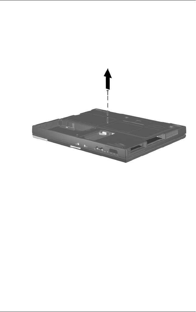
Removal and Replacement Procedures
Maintenance and Service Guide 5–19
1. Prepare the notebook for disassembly (Section 5.3).
2. Turn the notebook bottom side up with the front facing you.
3. Remove the TM2.5 × 7.0 screw that secures the keyboard to
the base enclosure (Figure 5-10).
Figure 5-10. Removing the Keyboard Screw
4. Turn the notebook top side up with the front facing you.
5. Open the notebook.
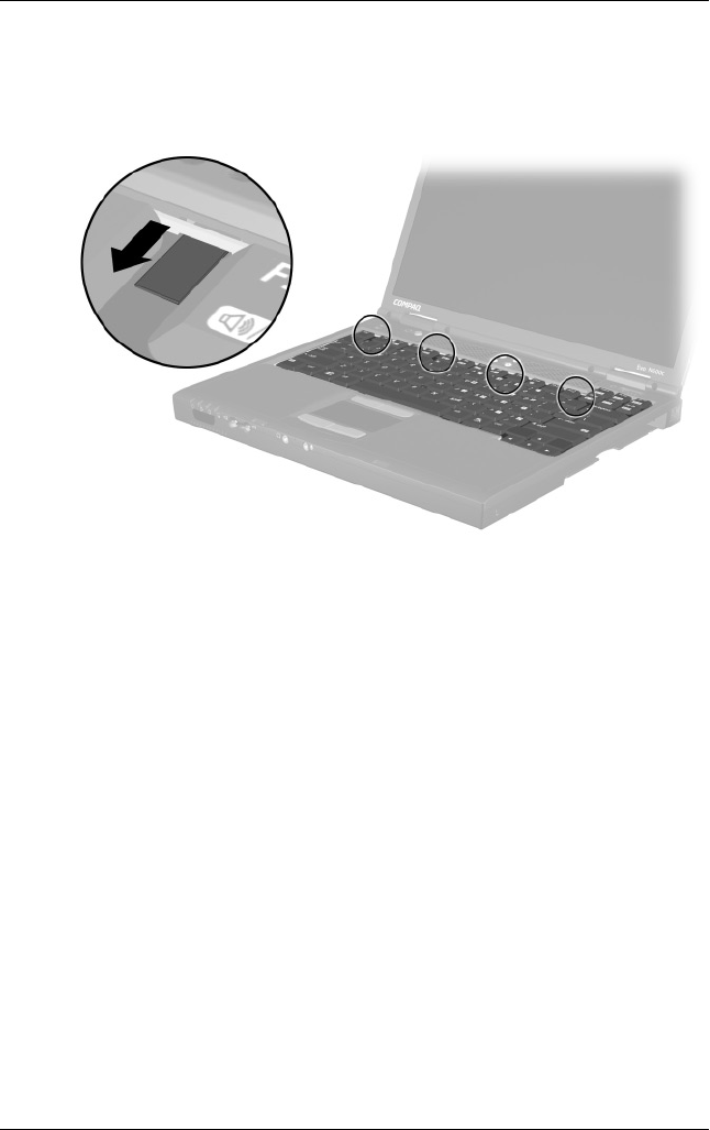
5–20 Maintenance and Service Guide
Removal and Replacement Procedures
6. Slide the four tabs on the top of the keyboard forward
(Figure 5-11).
Figure 5-11. Releasing the Keyboard
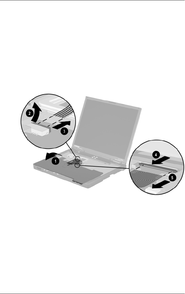
Removal and Replacement Procedures
Maintenance and Service Guide 5–21
7. Lift the top edge of the keyboard and swing it up and forward
until it rests on the top cover 1 (Figure 5-12).
8. Disengage the keyboard cable from the retaining clips in the
top cover.
9. Release the ZIF connector to which the pointing device cable
is attached 2 and disconnect the pointing device cable 3.
10. Release the ZIF connector to which the keyboard cable is
attached 4 and disconnect the keyboard cable 5.
Figure 5-12. Disconnecting the Pointing Device and
Keyboard Cables
11. Remove the keyboard.
Reverse the preceding procedure to replace the keyboard.

5–22 Maintenance and Service Guide
Removal and Replacement Procedures
5.8 Memory Expansion
✎Compaq Evo Notebook N600c models contain the mini PCI
communications board slot in this location. Refer to Section 5.5,
steps 6 through 8, for instructions on removing a mini PCI
communications board. The memory expansion compartment
cover is included in the Miscellaneous Plastics Kit (spare part
number 241439-001).
Memory Expansion Board
Spare Part Number Information
266 MHz, 2DM (for Evo Notebook N620c models only):
1024 MB
768 MB
512 MB
384 MB
256 MB
301576-001
301575-001
301574-001
301572-001
301571-001
133 MHz (for Evo Notebook N610c models only):
512 MB
256 MB
128 MB
64 MB
238879-001
212683-001
212682-001
212681-001
100 MHz (for Evo Notebook N600c models only):
512 MB
256 MB
128 MB
280875-001
280874-001
280873-001
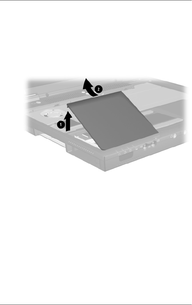
Removal and Replacement Procedures
Maintenance and Service Guide 5–23
1. Prepare the notebook for disassembly (Section 5.3).
2. Remove the keyboard (Section 5.7).
3. Lift the left side of the memory expansion compartment
cover 1 and swing the cover forward 2 (Figure 5-13).
4. Remove the memory expansion compartment cover.
Figure 5-13. Removing the Memory Expansion
Compartment Cover
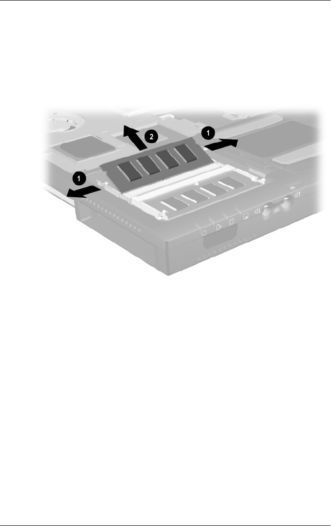
5–24 Maintenance and Service Guide
Removal and Replacement Procedures
5. Spread the retaining tabs 1 that secure the memory
expansion board to the socket. The board rises up at a
45-degree angle (Figure 5-14).
6. Pull the board away from the socket at a 45-degree angle 2.
Figure 5-14. Removing a Memory Expansion Board
Reverse the preceding procedure to replace a memory
expansion board.

Removal and Replacement Procedures
Maintenance and Service Guide 5–25
5.9 TouchPad
1. Prepare the notebook for disassembly (Section 5.3).
2. Remove the keyboard (Section 5.7).
3. Remove the memory expansion compartment cover
(Section 5.8).
TouchPad Components
Spare Part Number Information
For use with Evo Notebook N620c models only:
TouchButton with pointing stick buttons
(for use with Dual Stick models)
319772-001
For use with Evo Notebook N610c models only:
TouchPad (for use with TouchPad models)
TouchButton with pointing stick buttons
(for use with Dual Stick models)
253658-001
252434-001
For use with Evo Notebook N600c models only:
TouchPad (for use with TouchPad models)
TouchButton with pointing stick buttons
(for use with Dual Stick models)
135227-001
159530-001
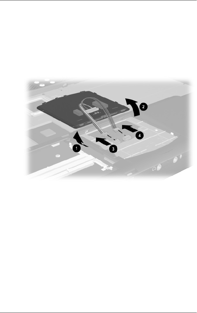
5–26 Maintenance and Service Guide
Removal and Replacement Procedures
4. Lift up on the left side of the TouchPad 1 until it disengages
from the top cover (Figure 5-15).
5. Swing the TouchPad up and back 2 and rest it on the
top cover.
6. Disconnect the TouchPad cables 3 and 4 from the
system board.
Figure 5-15. Removing the TouchPad
7. Remove the TouchPad.
Reverse the preceding procedure to replace the TouchPad.
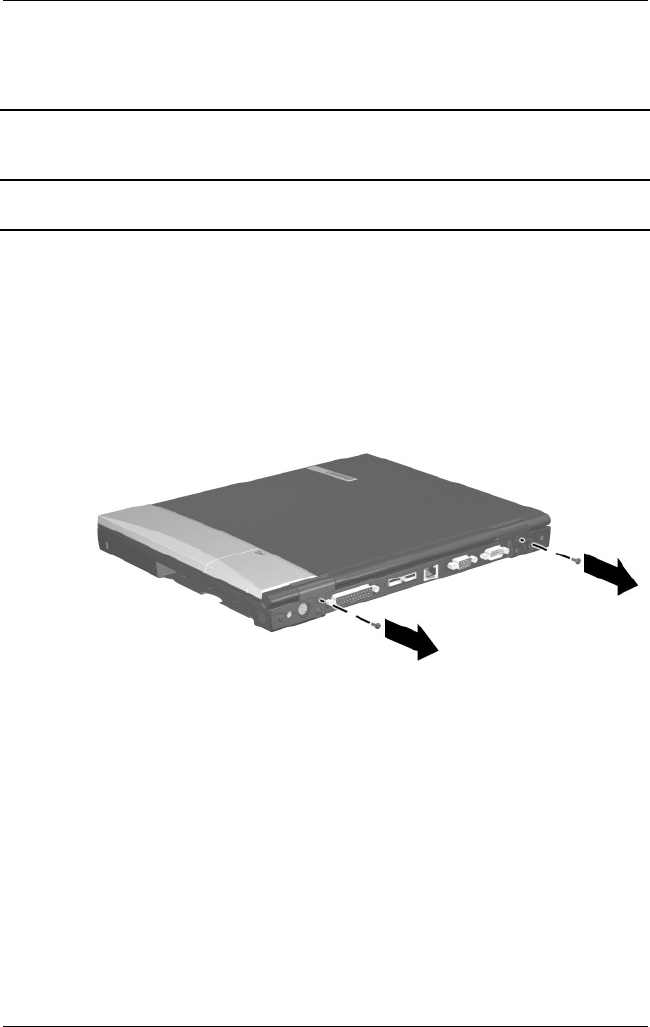
Removal and Replacement Procedures
Maintenance and Service Guide 5–27
5.10 Switch Cover
1. Prepare the notebook for disassembly (Section 5.3).
2. Remove the keyboard (Section 5.7).
3. Position the notebook so the rear panel faces you.
4. Remove the two black TM2.5 × 7.0 screws that secure the
switch cover to the base enclosure (Figure 5-16).
Figure 5-16. Removing the Switch Cover Screws
Switch Cover
Spare Part Number Information
Switch cover 241438-001
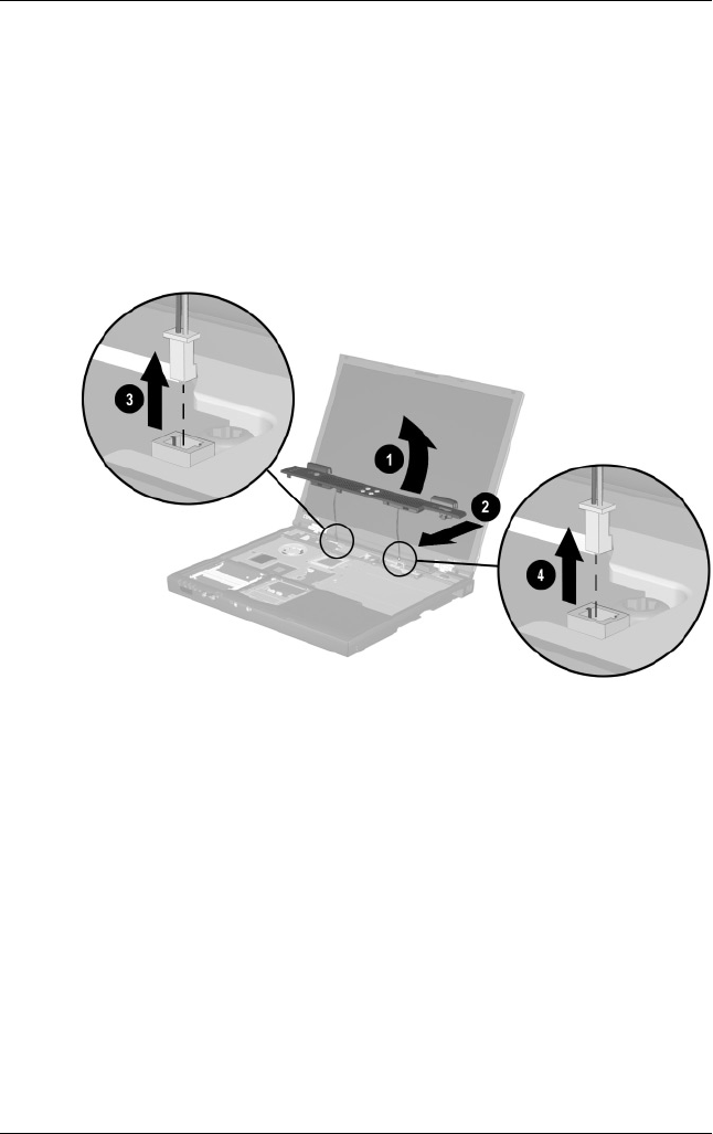
5–28 Maintenance and Service Guide
Removal and Replacement Procedures
5. Position the notebook so the front faces you.
6. Open the notebook as far as it will open.
7. Lift the switch cover up 1, slide it forward 2, and rest it on
the top cover (Figure 5-17).
8. Disconnect the left 3 and right speaker cables 4 from the
system board.
Figure 5-17. Removing the Switch Cover
9. Remove the switch cover.
Reverse the preceding procedure to replace the switch cover.

Removal and Replacement Procedures
Maintenance and Service Guide 5–29
5.11 Display
1. Prepare the notebook for disassembly (Section 5.3).
2. Remove the keyboard (Section 5.7).
3. Remove the switch cover (Section 5.10).
4. Position the display so that it is vertical.
Display
Spare Part Number Information
For use with Evo Notebook N620c models only
14.1-inch, SXGA+, CTFT 319733-001
For use with Evo Notebook N610c models only:
14.1-inch, SXGA+, CTFT
14.1-inch, XGA, CTFT
291261-001
291262-001
For use with Evo Notebook N600c models only:
14.1-inch, SXGA+, CTFT
14.1-inch, XGA, CTFT
241433-001
241434-001
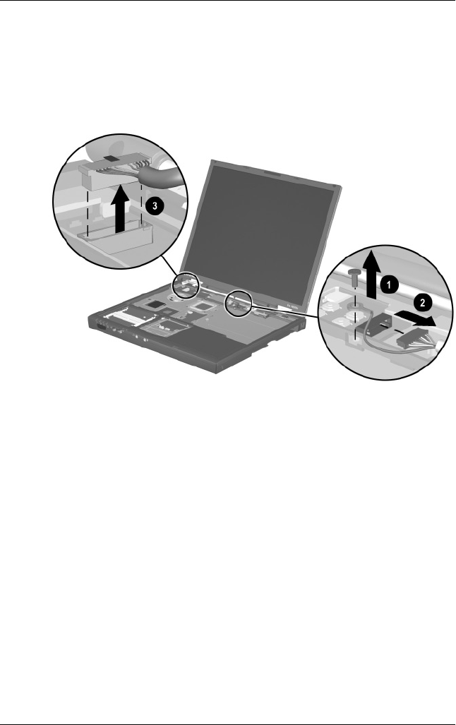
5–30 Maintenance and Service Guide
Removal and Replacement Procedures
5. Remove the TM2.5 × 7.0 screw that secures the display
ground cable to the top cover 1 (Figure 5-18).
6. Disconnect the display video 2 and inverter cables 3 from
the system board.
Figure 5-18. Disconnecting the Display Cables
7. Partially close the notebook.
8. Position the notebook so the rear panel faces you.
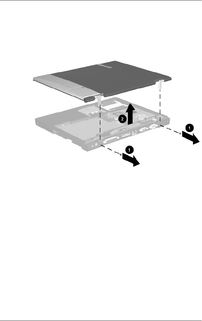
Removal and Replacement Procedures
Maintenance and Service Guide 5–31
9. Remove the two TM2.5 × 7.0 screws 1 that secure the
display to the base enclosure (Figure 5-19).
10. Lift the display straight up and remove it from the base
enclosure 2.
Figure 5-19. Removing the Display
Reverse the preceding procedure to replace the display.

5–32 Maintenance and Service Guide
Removal and Replacement Procedures
5.12 Top Cover
1. Prepare the notebook for disassembly (Section 5.3) and
remove the following components:
a. Keyboard (Section 5.7)
b. Memory expansion compartment cover (Section 5.8)
c. Switch cover (Section 5.10)
d. Display (Section 5.11)
2. Turn the notebook bottom side up with the rear panel
facing you.
Top Cover
Spare Part Number Information
For use with Evo Notebook N620c and N610c models only
For use with Evo Notebook N600c models only
291264-001
241436-001
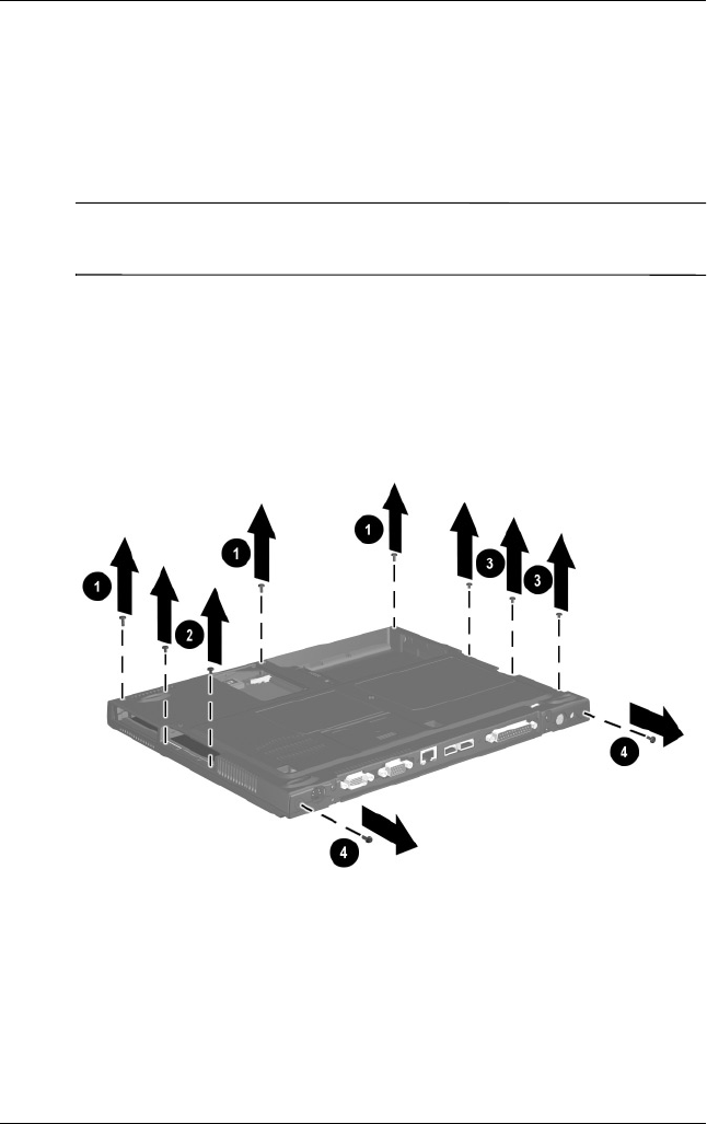
Removal and Replacement Procedures
Maintenance and Service Guide 5–33
3. Remove the following screws:
❏Three TM2.5 × 7.0 screws from the front edge of the base
enclosure 1 (Figure 5-20)
❏Two TM2.5 × 5.0 screws from the hard drive bay 2
✎The Evo Notebook N620c contains two TM2.5 × 7.0 screws in
the hard drive bay.
❏Two TM2.5 × 5.0 screws from the Media Bay 3
❏Evo Notebook N620c and N600c models—Two
TM2.5 × 5.0 screws from the rear panel 4, or
❏Evo Notebook N610c models—Two TM2.5 × 7.0
screws from the rear panel 4
Figure 5-20. Removing the Top Cover Screws
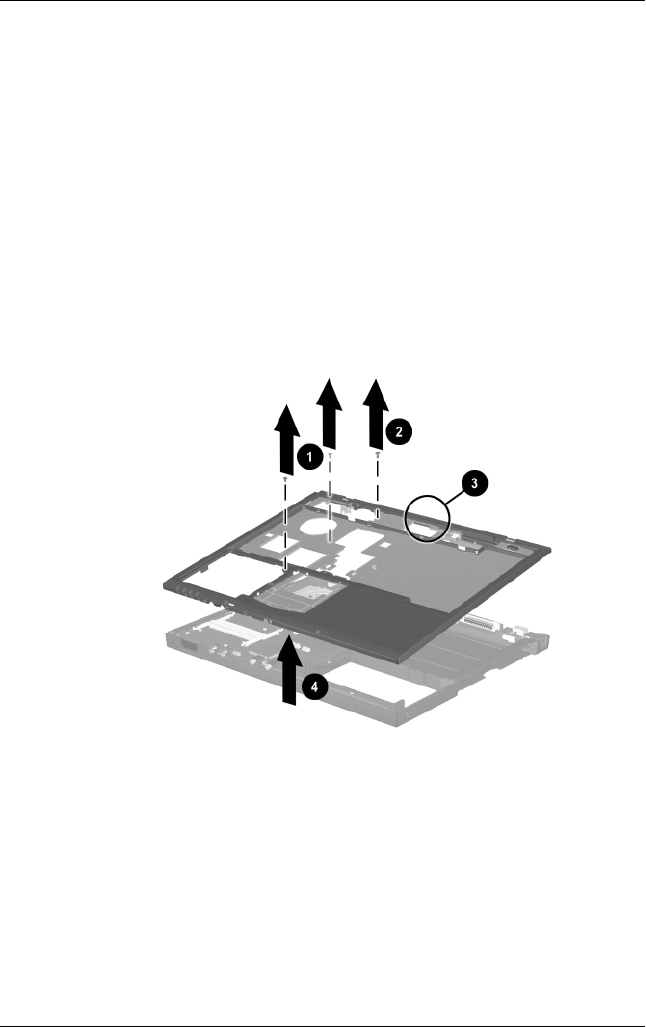
5–34 Maintenance and Service Guide
Removal and Replacement Procedures
4. Turn the notebook top side up with the front facing you.
5. For Evo Notebook N620c and N610c models
only—Remove the two TM2.0 × 4.0 1 screws that secure the
top cover to the base enclosure (Figure 5-21).
6. For all notebook models—Remove the TM2.5 × 7.0 2
screw that secures the top cover to the base enclosure.
7. Insert a flat blade screwdriver into the slot 3 on the rear edge
of the top cover to disengage the cover from the I/O bracket.
8. Lift the top cover straight up and remove it from the base
enclosure 4.
Figure 5-21. Removing the Top Cover
Reverse the preceding procedure to replace the top cover.

Removal and Replacement Procedures
Maintenance and Service Guide 5–35
5.13 System Board
✎Make sure the PC Card eject buttons are fully depressed and there
are no PC Card devices or space savers inserted into the PC Card
slots before removing the system board.
1. Prepare the notebook for disassembly (Section 5.3) and
remove the following components:
a. RTC battery (Section 5.6)
b. Keyboard (Section 5.7)
c. Memory expansion compartment cover (Section 5.8)
d. TouchPad (Section 5.9)
e. Switch cover (Section 5.10)
f. Display (Section 5.11)
g. Top cover (Section 5.12)
2. Position the notebook so the rear panel faces you.
System Board
Spare Part Number Information
For use with Evo Notebook N620c models only
For use with Evo Notebook N610c models only
For use with Evo Notebook N600c models only:
Mobile Intel Pentium III processor 1.066 GHz-M
Mobile Intel Pentium III processor 866 MHz-M
319778-001
291581-001
241430-001
241432-001
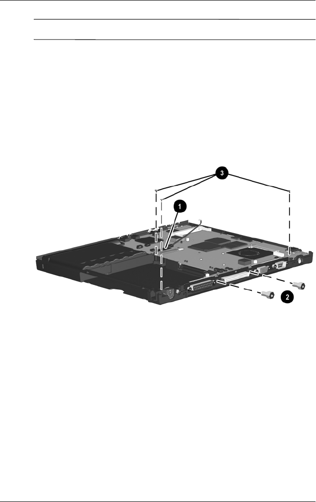
5–36 Maintenance and Service Guide
Removal and Replacement Procedures
✎Steps 3 through 5 apply only to Evo Notebook N600c models.
3. Remove the tape that secures the modem cable to the system
board 1 (Figure 5-22).
4. Remove the two 7.0-mm bushing guides 2 on either side of
the docking connector that secure the system board to the
base enclosure.
5. Remove the three TM2.5 × 5.0 screws 3 that secure the
system board to the base enclosure.
Figure 5-22. Removing the System Board Screws and
Bushing Guides on an Evo Notebook N600c
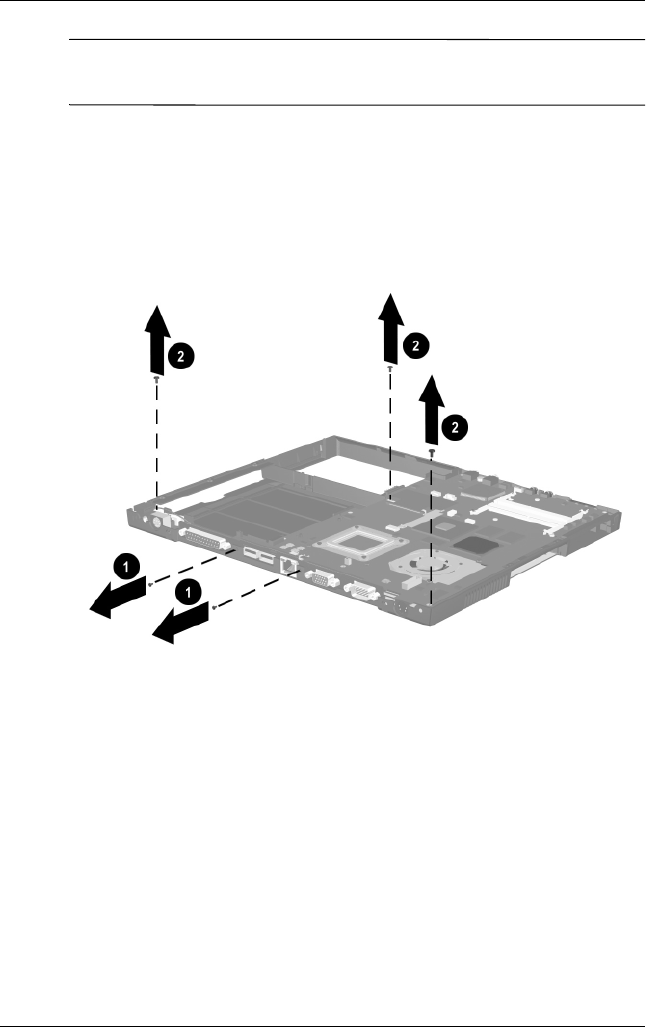
Removal and Replacement Procedures
Maintenance and Service Guide 5–37
✎Steps 6 and 7 apply only to Evo Notebook N620c and
N610c models.
6. Remove the two TM2.5 × 5.0 screws 1 that secure the
system board to the base enclosure through the rear panel
(Figure 5-23).
7. Remove the three TM2.5 × 5.0 screws 2 that secure the top
cover to the base enclosure.
Figure 5-23. Removing the System Board Screws on
Evo Notebook N620c and N610c Models
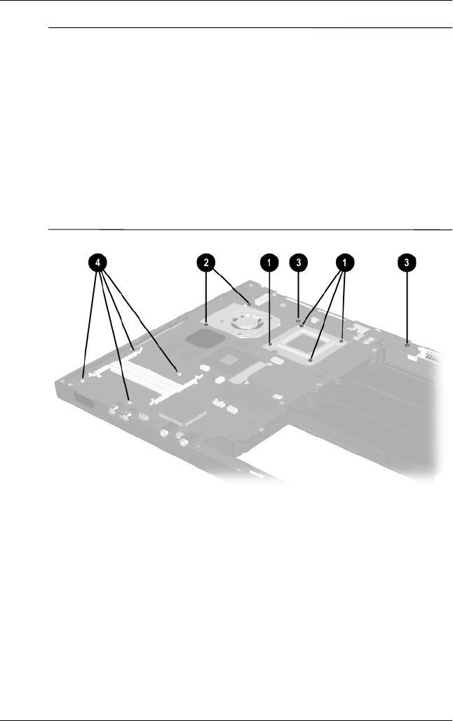
5–38 Maintenance and Service Guide
Removal and Replacement Procedures
✎When removing the system board, do not remove the following
screws (Figure 5-24):
■Four screws 1 that secure the processor bracket to the
system board
■Two screws 2 that secure the heat sink to the
system board
■Two screws 3 that secure the hard drive connector the
system board
■Four screws 4 that secure the PC Card assembly to
the system board
Figure 5-24. Do Not Remove These Screws
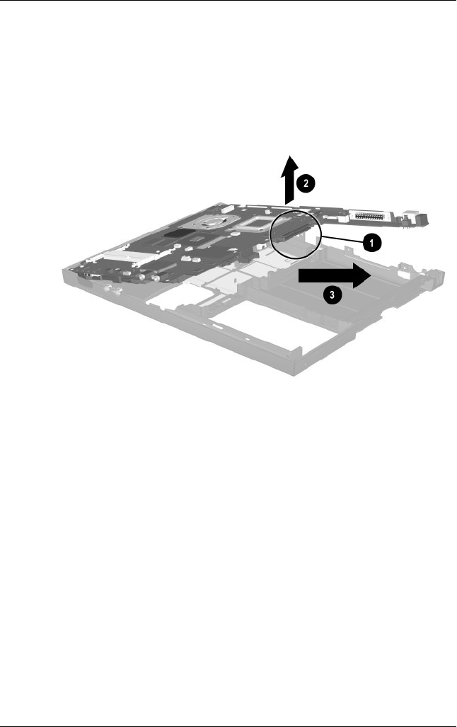
Removal and Replacement Procedures
Maintenance and Service Guide 5–39
8. Use the Media Bay connector 1 to lift the right side of the
system board 2 until it rests at a 45-degree angle
(Figure 5-25).
9. Slide the system board out of the base enclosure at a
45-degree angle 3.
Figure 5-25. Removing the System Board
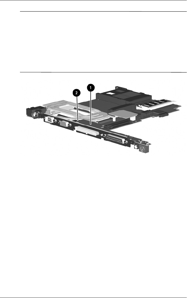
5–40 Maintenance and Service Guide
Removal and Replacement Procedures
✎Figure 5-26 applies only to Evo Notebook N600c models. When
handling the system board, be careful not to put stress on the I/O
interface board 1. The narrow profile of this board makes it
susceptible to being damaged when mishandled. Do not remove
the screw 2 that secures the I/O interface board to the system
board or attempt to remove the I/O interface board. The system
board should only be removed and handled using the Media Bay
connector, as illustrated in Figure 5-26.
Figure 5-26. Proper Handling of the I/O Interface Board on an
Evo Notebook N600c
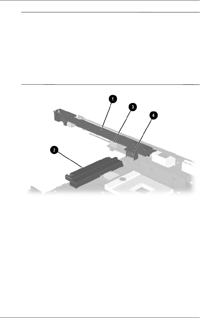
Removal and Replacement Procedures
Maintenance and Service Guide 5–41
✎Figure 5-27 applies only to Evo Notebook N620c and N610c
models. When handling the system board, be careful not to put
stress on the I/O interface board 1. The narrow profile of this
board makes it susceptible to being damaged when mishandled.
The system board should only be removed and handled using the
Media Bay connector 2. After the system board is installed in the
base enclosure, apply gentle downward pressure on the I/O
interface board directly above the two connectors 3 and 4 that
connect the I/O interface board to the system board.
Figure 5-27. Proper Handling of the I/O Interface Board on
Evo Notebook N620c and N610c Models
Reverse the preceding procedure to replace the system board.

5–42 Maintenance and Service Guide
Removal and Replacement Procedures
5.14 Fan
1. Prepare the notebook for disassembly (Section 5.3) and
remove the following components:
a. RTC battery (Section 5.6)
b. Keyboard (Section 5.7)
c. Memory expansion compartment cover (Section 5.8)
d. TouchPad (Section 5.9)
e. Switch cover (Section 5.10)
f. Display (Section 5.11)
g. Top cover (Section 5.12)
h. System board (Section 5.13)
2. Turn the system board bottom side up with the rear panel
facing you.
Fan
Spare Part Number Information
For use with Evo Notebook N620c and N610c models only
For use with Evo Notebook N600c models only
291266-001
255528-001
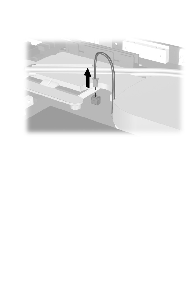
Removal and Replacement Procedures
Maintenance and Service Guide 5–43
3. Disconnect the fan cable from the system board
(Figure 5-28).
Figure 5-28. Disconnecting the Fan Cable
4. Turn the system board top side up with the rear panel
facing you.
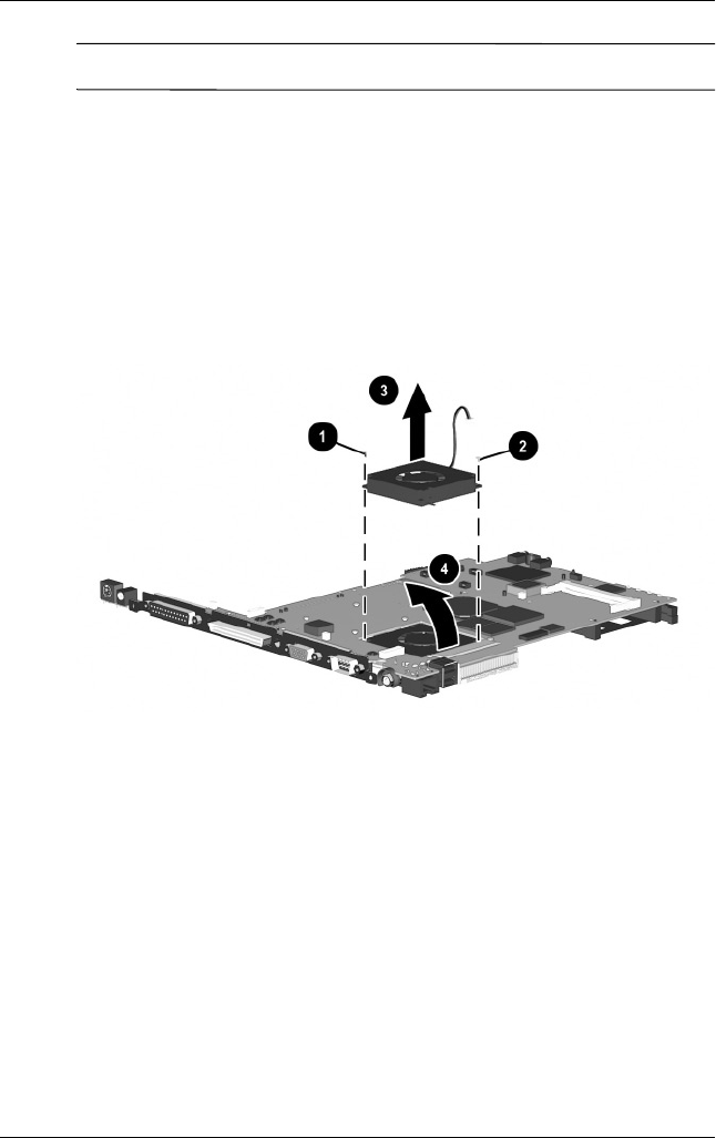
5–44 Maintenance and Service Guide
Removal and Replacement Procedures
✎Steps 5 through 7 apply only to Evo Notebook N600c models.
5. Remove the PM2.0 × 4.0 screw 1 and PM2.5 × 5.0 screw 2
that secure the fan to the system board (Figure 5-29).
6. While holding the system board above the work surface, push
the left side of the fan up 3 from the bottom of the system
board.
7. When the left edge of the fan has cleared the system board,
slide the fan to the left 4 and out of the heat sink.
Figure 5-29. Removing the Fan on an Evo Notebook N600c
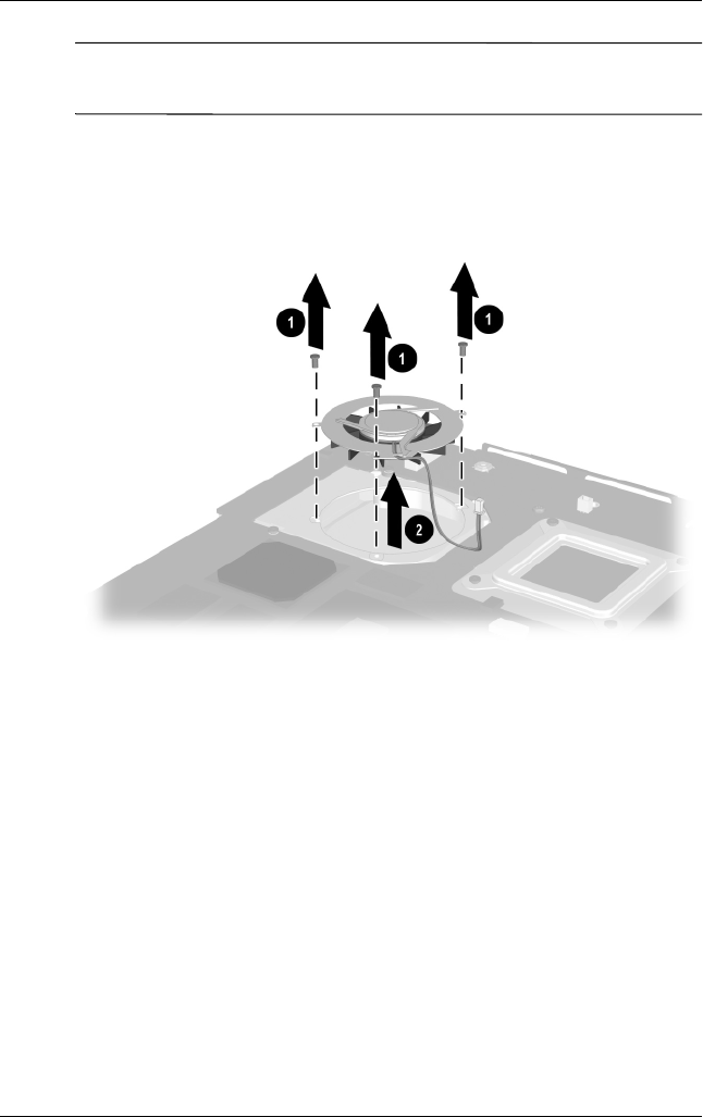
Removal and Replacement Procedures
Maintenance and Service Guide 5–45
✎Steps 8 and 9 apply only to Evo Notebook N620c and
N610c models.
8. Remove the three PM2.0 × 4.0 screws 1 that secure the fan to
the heat sink (Figure 5-30).
9. Lift the fan out of the heat sink 2.
Figure 5-30. Removing the Fan on Evo Notebook N620c and
N610c Models
10. Remove the fan.
Reverse the preceding procedure to replace the fan.

5–46 Maintenance and Service Guide
Removal and Replacement Procedures
5.15 Heat Sink
✎This section applies only to Evo Notebook N620c and
N610c models.
1. Prepare the notebook for disassembly (Section 5.3) and
remove the following components:
a. RTC battery (Section 5.6)
b. Keyboard (Section 5.7)
c. Memory expansion compartment cover (Section 5.8)
d. TouchPad (Section 5.9)
e. Switch cover (Section 5.10)
f. Display (Section 5.11)
g. Top cover (Section 5.12)
h. System board (Section 5.13)
Heat Sink
Spare Part Number Information
Heat sink 303103-001
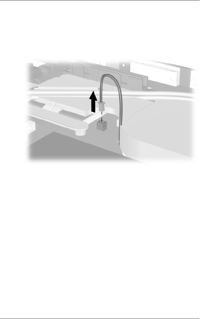
Removal and Replacement Procedures
Maintenance and Service Guide 5–47
2. Turn the system board bottom side up with the rear panel
facing you.
3. Disconnect the fan cable from the system board
(Figure 5-31).
Figure 5-31. Disconnecting the Fan Cable
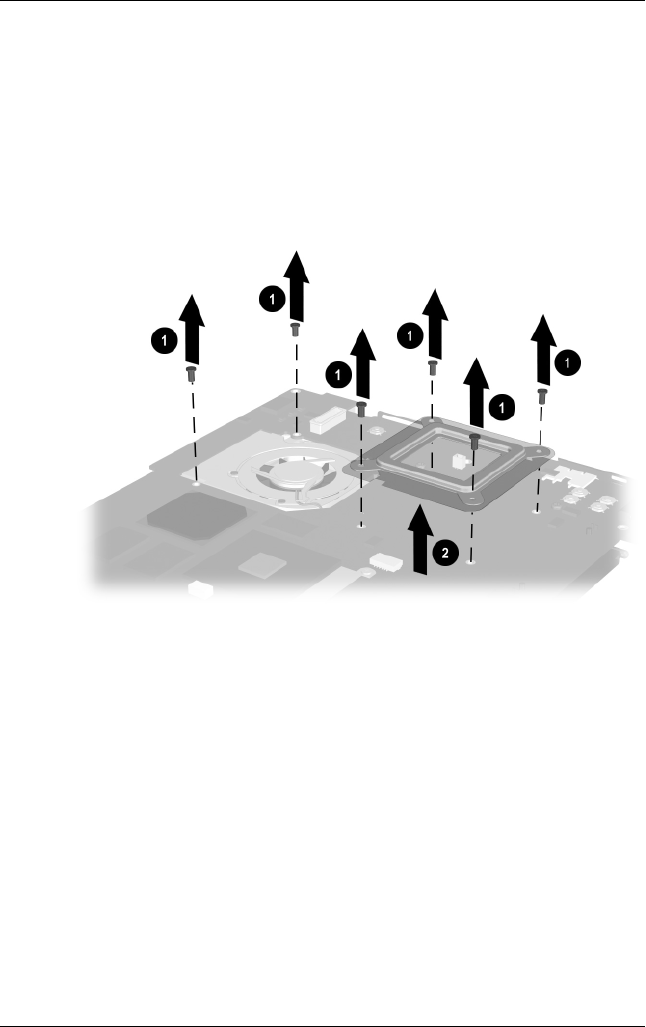
5–48 Maintenance and Service Guide
Removal and Replacement Procedures
4. Turn the system board top side up with the rear panel
facing you.
5. Remove the six PM2.0 × 4.0 screws 1 that secure the
processor mounting bracket and heat sink to the system board
(Figure 5-32).
6. Remove the processor mounting bracket 2.
Figure 5-32. Removing the Heat Sink Screws
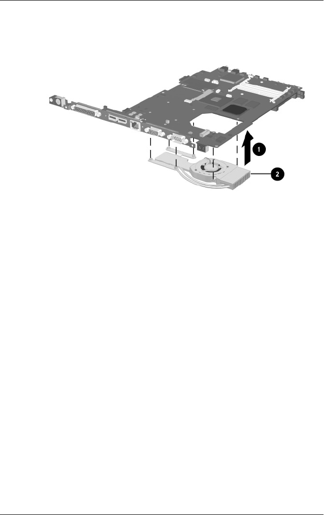
Removal and Replacement Procedures
Maintenance and Service Guide 5–49
7. Lift the system board straight up 1. The heat sink 2 will
remain resting on the work surface (Figure 5-33).
Figure 5-33. Removing the Heat Sink
Reverse the preceding procedure to replace the heat sink.

5–50 Maintenance and Service Guide
Removal and Replacement Procedures
5.16 Processor
✎This section applies only to Evo Notebook N620c and
N610c models.
1. Prepare the notebook for disassembly (Section 5.3) and
remove the following components:
a. RTC battery (Section 5.6)
b. Keyboard (Section 5.7)
c. Memory expansion compartment cover (Section 5.8)
d. TouchPad (Section 5.9)
e. Switch cover (Section 5.10)
f. Display (Section 5.11)
g. Top cover (Section 5.12)
h. System board (Section 5.13)
i. Heat sink (Section 5.15)
Processor
Spare Part Number Information
For use only with Evo Notebook N620c models
Intel Pentium-M 1.6 GHz
Intel Pentium-M 1.5 GHz
Intel Pentium-M 1.4 GHz
Intel Pentium-M 1.3 GHz
319777-001
319776-001
319775-001
319774-001
For use only with Evo Notebook N610c models
Mobile Intel Pentium 4 2.0 GHz
Mobile Intel Pentium 4 1.8 GHz
Mobile Intel Pentium 4 1.7 GHz
Mobile Intel Pentium 4 1.6 GHz
303282-001
291269-001
291268-001
291267-001
Intel Celeron 1.5 GHz 309420-001
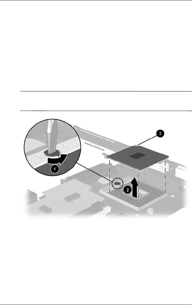
Removal and Replacement Procedures
Maintenance and Service Guide 5–51
2. Turn the system board bottom side up with the rear panel
facing you.
3. Insert the tip of a flat-blade screwdriver into the slot on the
processor locking screw.
4. Turn the screwdriver counterclockwise 1 to release the
processor (Figure 5-34).
5. Remove the processor from the socket on the system
board 2.
✎When installing the processor, make sure the gold triangle 3 is in
the lower right corner.
Figure 5-34. Removing the Processor
Reverse the preceding procedure to replace the processor.

5–52 Maintenance and Service Guide
Removal and Replacement Procedures
5.17 DC-DC Converter Board
1. Prepare the notebook for disassembly (Section 5.3) and
remove the following components:
a. RTC battery (Section 5.6)
b. Keyboard (Section 5.7)
c. Memory expansion compartment cover (Section 5.8)
d. TouchPad (Section 5.9)
e. Switch cover (Section 5.10)
f. Display (Section 5.11)
g. Top cover (Section 5.12)
h. System board (Section 5.13)
2. Turn the system board bottom side up with the rear panel
facing you.
DC-DC Converter Board
Spare Part Number Information
For use with Evo Notebook N620c models only
For use with Evo Notebook N610c models only
For use with Evo Notebook N600c models only
319635-001
291263-001
241435-001
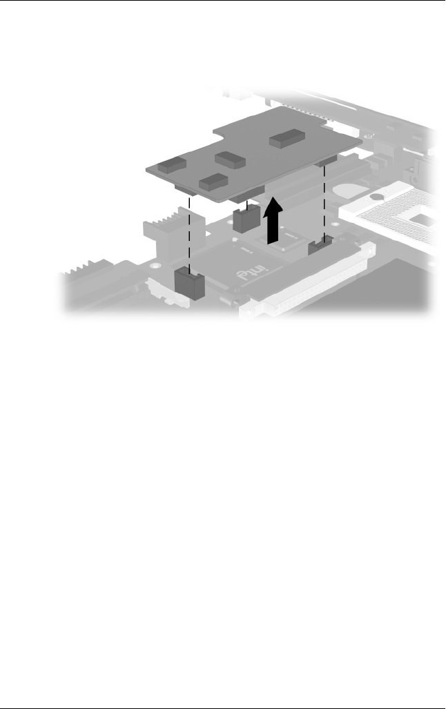
Removal and Replacement Procedures
Maintenance and Service Guide 5–53
3. Lift the left and right edges of the DC-DC converter board to
disconnect the board from the system board (Figure 5-35).
Figure 5-35. Removing the DC-DC Converter Board
4. Remove the DC-DC converter board.
Reverse the preceding procedure to replace the DC-DC converter
board.

5–54 Maintenance and Service Guide
Removal and Replacement Procedures
5.18 Modem Cable
✎The modem cable is spared with the base enclosure. Modem
cables are also included in the Miscellaneous Plastics Kit
(spare part number 241439-001).
1. Prepare the notebook for disassembly (Section 5.3) and
remove the following components:
a. RTC battery (Section 5.6)
b. Keyboard (Section 5.7)
c. Memory expansion compartment cover (Section 5.8)
d. TouchPad (Section 5.9)
e. Switch cover (Section 5.10)
f. Display (Section 5.11)
g. Top cover (Section 5.12)
h. System board (Section 5.13)
2. Position the base enclosure with the rear panel facing
forward.
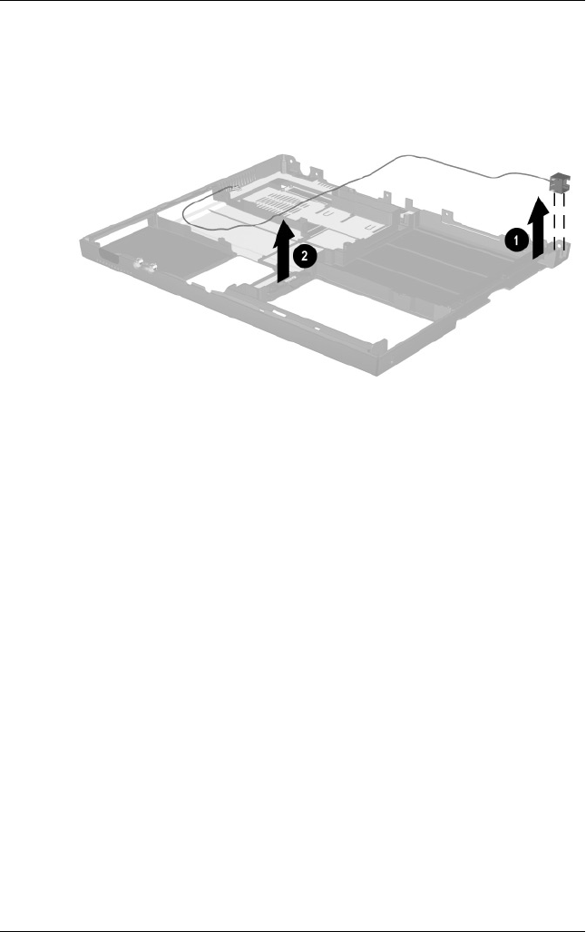
Removal and Replacement Procedures
Maintenance and Service Guide 5–55
3. Lift the modem connector out of the base enclosure 1 and
disengage the modem cable 2 from the alignment clips and
tabs in the base enclosure (Figure 5-36).
Figure 5-36. Removing the Modem Cable
4. Remove the modem cable.
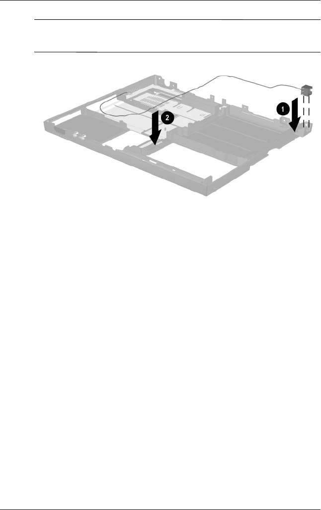
5–56 Maintenance and Service Guide
Removal and Replacement Procedures
✎When installing the modem cable, route the cable along the path
indicated in Figure 5-37.
Figure 5-37. Routing the Modem Cable in the Base Enclosure

Maintenance and Service Guide 6–1
6
Specifications
This chapter provides physical and performance specifications.
Table 6-1
Notebook
Dimensions
Height
Width
Depth
3.1 cm
30.7 cm
25.0 cm
1.2 in
12.1 in
9.8 in
Weight
With 8-cell battery pack and
optical drive in Media Bay
With 8-cell battery pack and
Media Bay weight saver
2.5 kg
2.1 kg
5.5 lb
4.8 lb
Stand-alone (battery) power requirements
Nominal operating voltage
(Li ion)
Average operating power
Peak operating power
Power in Suspend
Power in Hibernation
14.4 V
15.8 W
38 W
< 800 mW
< 100 mW
AC adapter power requirements
Rated input voltage
Rated input current
Rated frequency
90 to 264 VAC (auto switching)
< 60 W
47 to 63 Hz

6–2 Maintenance and Service Guide
Specifications
✎Applicable product safety standards specify thermal limits for
plastic surfaces. The notebook operates well within this range of
temperatures.
Temperature
Operating
Nonoperating
10° C to 35° C
-20° C to 60° C
50° F to 95° F
-4° F to 140° F
Relative humidity (noncondensing)
Operating
Nonoperating
10 to 90%
5 to 95%, 38.7° C/101.6° F maximum
wetbulb
Altitude (unpressurized)
Operating
Nonoperating
0 to 3,048 m
0 to 9,144 m
0 to 10,000 ft
0 to 30,000 ft
Shock
Operating
Nonoperating
10 G for 11 ms, half sine
60 G for 11 ms, half sine
Vibration
Operating
Nonoperating
0.5 G zero-to-peak, 10–500 Hz,
0.25-oct/min sweep rate
1.0 G zero-to-peak, 10–500 Hz,
0.25-oct/min sweep rate
Table 6-1
Notebook
(Continued)

Specifications
Maintenance and Service Guide 6–3
Table 6-2
14.1-inch XGA, TFT Display
Dimensions
Height
Depth
Width
21.40 cm
28.50 cm
35.81 cm
8.46 in
11.22 in
14.10 in
Number of colors Up to 16.8 million
Contrast ratio 150:1
Brightness 120 nits typical
Pixel resolution
Pitch
Format
Configuration
0.264 × 0.264 mm
1024 × 768
RGB vertical stripe
Backlight Edge lit
Character display 80 × 25
Refresh 60 Hz
Total power
consumption
4.2 W

6–4 Maintenance and Service Guide
Specifications
Table 6-3
Hard Drives
40.0 GB 30.0 GB 20.0 GB 15.0 GB
User capacity
per drive1
40.0 30.0 GB 20.0 GB 15.0 GB
Drive height 9.5 mm 9.5 mm 9.5 mm 9.5 mm
Drive width 70.0 mm 70.0 mm 70.0 mm 70.0 mm
Interface type ATA - 5 ATA - 5 ATA - 5 ATA - 4
Seek times (typical read, including setting)
Single track
Average
Full stroke
2.5 ms
12.0 ms
23.0 ms
2.5 ms
12.0 ms
23.0 ms
2.5 ms
12.0 ms
23.0 ms
2.5 ms
13.0 ms
24.0 ms
User addressable
sectors3
78,140,160 58,605,120 39,070,080 23,579,136
Logical configuration
Cylinders
Heads
Sectors per track
16,383
16
63
16,383
16
63
16,383
16
63
16,683
16
63
11 GB = 1,000,000,000 bytes.
3Actual drive specifications may differ slightly.
Certain restrictions and exclusions apply. Consult the Compaq Customer
Support Center for details.

Specifications
Maintenance and Service Guide 6–5
40.0 GB 30.0 GB 20.0 GB 15.0 GB
Physical
configuration
Cylinders3
Heads
Sectors per
track3
Bytes per sector
22,784
4
293 to 560
512
25,800
2
398 to 731
512
22,784
4
293 to 560
512
25,800
2
398 to 731
512
Buffer size32 MB 512 KB 512 KB 512 KB
Disk rotational
speed
4200 rpm 4200 rpm 4200 rpm 4200 rpm
Transfer rate
Interface max
(MB/s)2
Media (Mb/s)3
66.6
109 to 203
100
109 to 203
66.6
109 to 203
100
109 to 203
2System capability may differ.
3Actual drive specifications may differ slightly.
Certain restrictions and exclusions apply. Consult the Compaq Customer
Support Center for details.
Table 6-3
Hard Drives
(Continued)

6–6 Maintenance and Service Guide
Specifications
Table 6-4
Diskette Drive
Diskette size 3.5 in
Light On system
Height 12.7 mm 0.5 in
Bytes per sector 512
Sectors per track
High density
Low density
18 (1.44 MB)
9
15 (1.2 MB)
Tracks per side
High density
Low density
80
80
Read/write heads 2
Average seek times
Track-to-track (high/low)
Average (high/low)
Settling time
Latency average
3 to 6 ms
94 to 174 ms
15 ms
100 ms

Specifications
Maintenance and Service Guide 6–7
Table 6-5
CD-ROM Drive
Applicable disc CD-ROM (Mode 1, 2, and 3)
CD-XA ready (Mode 2, Form 1 and 2)
CD-I ready (Mode 2, Form 1 and 2)
CD-R (read only)
CD Plus
Photo CD (single/multisession)
CD-Extra
Video CD
CD-WO (fixed packets only)
CD-Bridge
Center hole diameter 1.5 cm 0.59 in
Disc diameter 12 cm, 8 cm
Disc thickness 1.2 mm
Track pitch 1.6 µm
Access time
Random
Full stroke
< 150 ms
< 300 ms
Cache buffer 128 KB
Data transfer rate
Sustained, 16X
Variable
Normal PIO Mode 4 (single burst)
150 KB/s at 1X
1500 to 3600 KB/s (10X to 24X)
16.66 KB/s
Startup time < 8 seconds
Stop time < 4 seconds

6–8 Maintenance and Service Guide
Specifications
Table 6-6
DVD-ROM Drive
Applicable disc DVD-5, DVD-9, DVD-10
CD-ROM (Mode 1 and 2)
CD Digital Audio
CD-XA ready (Mode 2, Form 1 and 2)
CD-I ready (Mode 2, Form 1 and 2)
CD-R (read only)
CD Plus
Photo CD (single/multisession)
CD-Bridge
Center hole diameter 1.5 cm 0.59 in
Disc diameter 12 cm, 8 cm
Disc thickness 1.2 mm
Track pitch 0.74 µm
Access time
Random
Full stroke
< 150 ms
< 225 ms
Audio output level Line-out, 0.7 Vrms
Cache buffer 512 KB/sec
Data transfer rate
Max 24X CD
Max 8X DVD
Normal IO Mode 4 (single burst)
3600 KB/s (150 KB/s at 1X CD rate)
10,800 KB/s
(1352 KB/s at 1X DVD rate)
16.6 MB/s
Startup time < 12 seconds
Stop time < 3 seconds

Specifications
Maintenance and Service Guide 6–9
Table 6-7
CD-RW Drive
Center hole diameter 0.39 cm 0.59 in
Disk diameter 12 cm, 8 cm
Disk thickness 0.12 cm 0.47 in
Track pitch 0.74 µm
Access time
Random
Full stroke
< 150 ms
< 225 ms
Audio output level Line-out, 0.7 Vrms
Cache buffer 128 KB/s minimum
Data transfer rate
Sustained, 16X
Sustained, 4X CD-RW
Normal PIO Mode 4 (single burst)
150 KB/s
5,520 KB/s
16.6 MB/s
Startup time < 15 seconds
Stop time < 6 seconds

6–10 Maintenance and Service Guide
Specifications
Table 6-8
AC Adapter
Dimensions
Height
Depth
Width
2.79 cm
3.61 cm
9.40 cm
1.10 in
1.42 in
3.70 in
Weight 0.18 kg 0.39 lb
Power supply (input)
Operating voltage
Operating current
Operating frequency range
Maximum transient
90 to 260 VAC RMS nominal
1.3 A RMS
47 to 63 Hz nominal
4/50 kV
Table 6-9
8-cell, Li ion Battery Pack
Dimensions
Length
Width
Depth
Weight
125.80 cm
88.00 cm
20.40 cm
0.43 kg
4.95 in
3.46 in
0.80 in
0.96 lb
Energy
Voltage
Amp-hour capacity
Watt-hour capacity
14.8 V
Minimum 3.7 Ah, typical 3.9 Ah
Minimum 53.2 Ah, typical 56.1 Ah
Temperature
Operating
Nonoperating
0 to 42° C
0 to 60° C
32 to 108° F
32 to 140° F

Specifications
Maintenance and Service Guide 6–11
Table 6-10
System DMA
Hardware DMA System Function
DMA0 Available for audio
DMA1 Entertainment audio
(default; alternate = DMA0, DMA3, none)
DMA2 Diskette drive
DMA3 ECP parallel port LPT1
(default; alternate = DMA0, none)
DMA4 DMA controller cascading (not available)
DMA5 Available for PC Card
DMA6 Not assigned
DMA7 Not assigned
✎PC Card controller can use DMA 1, 2, or 5.

6–12 Maintenance and Service Guide
Specifications
Table 6-11
System Interrupts
Hardware IRQ System Function
IRQ0 System timer
IRQ1 Keyboard controller
IRQ2 Cascaded
IRQ3 COM2
IRQ4 COM1
IRQ5 Audio (default)*
IRQ6 Diskette drive
IRQ7 Parallel port
IRQ8 Real time clock (RTC)
IRQ9 Infrared
IRQ10 System use
IRQ11 System use
IRQ12 Internal point stick or external mouse
IRQ13 Coprocessor (not available to any peripheral)
IRQ14 IDE interface (hard drive and optical drive)
IRQ15 System use
✎PC Cards may assert IRQ3, IRQ4, IRQ5, IRQ7, IRQ9, IRQ10,
IRQ11, or IRQ15. Either the infrared or the serial port may assert
IRQ3 or IRQ 4.
*Default configuration; audio possible configurations are IRQ5, IRQ7, IRQ9,
IRQ10, or none.

Specifications
Maintenance and Service Guide 6–13
Table 6-12
System I/O Addresses
I/O Address (hex) System Function (shipping configuration)
000–00F DMA controller no. 1
010–01F Unused
020–021 Interrupt controller no. 1
022– 024 Opti chipset configuration registers
025–03F Unused
02E–02F 87334 “Super IO” configuration for CPU
040–05F Counter/timer registers
044–05f Unused
060 Keyboard controller
061 Port B
062–063 Unused
064 Keyboard controller
065–06F Unused
070–071 NMI enable/real time clock
072–07F Unused
080–08F DMA page registers
090–091 Unused
092 Port A
093–09F Unused
0A0–0A1 Interrupt controller no. 2

6–14 Maintenance and Service Guide
Specifications
I/O Address (hex) System Function (shipping configuration)
0A2–0BF Unused
0C0–0DF DMA controller no. 2
0E0–0EF Unused
0F0–0F1 Coprocessor busy clear/reset
0F2–0FF Unused
100–16F Unused
170–177 Secondary fixed disk controller
178–1EF Unused
1F0–1F7 Primary fixed disk controller
1F8–200 Unused
201 Joystick (decoded in ESS1688)
202–21F Unused
220–22F Entertainment audio
230–26D Unused
26E–26 Unused
278–27F Unused
280–2AB Unused
2A0–2A7 Unused
2A8–2E7 Unused
2E8–2EF Reserved serial port
Table 6-12
System I/O Addresses
(Continued)

Specifications
Maintenance and Service Guide 6–15
I/O Address (hex) System Function (shipping configuration)
2F0–2F7 Unused
2F8–2FF Infrared port
300–31F Unused
320–36F Unused
370–377 Secondary diskette drive controller
378–37F Parallel port (LPT1/default)
380–387 Unused
388–38B FM synthesizer - OPL3
38C–3AF Unused
3B0–3BB VGA
3BC–3BF Reserved (parallel port/no EPP support)
3C0–3DF VGA
3E0–3E1 PC Card controller in CPU
3E2–3E3 Unused
3E8–3EF Internal modem
3F0–3F7 “A” diskette controller
3F8–3FF Serial port (COM1/default)
CF8–CFB PCI configuration index register (PCIDIVO-1)
CFC–CFF PCI configuration data register (PCIDIVO-1)
Table 6-12
System I/O Addresses
(Continued)

6–16 Maintenance and Service Guide
Specifications
Table 6-13
System Memory Map
Size Memory Address System Function
640 KB 00000000 - 0009FFFF Base memory
128 KB 000A0000 - 000BFFFF Video memory
48 KB 000C0000 - 000CBFFF Video BIOS
160 KB 000C8000 - 000E7FFF Unused
64 KB 000E8000 - 000FFFFF System BIOS
15 MB 00100000 - 00FFFFFF Extended memory
58 MB 01000000 - 047FFFFF Super extended memory
58 MB 04800000 - 07FFFFFF Unused
2 MB 08000000 - 080FFFFF Video memory (direct access)
4 GB 08200000 - FFFEFFFF Unused
64 KB FFFF0000 - FFFFFFFF System BIOS
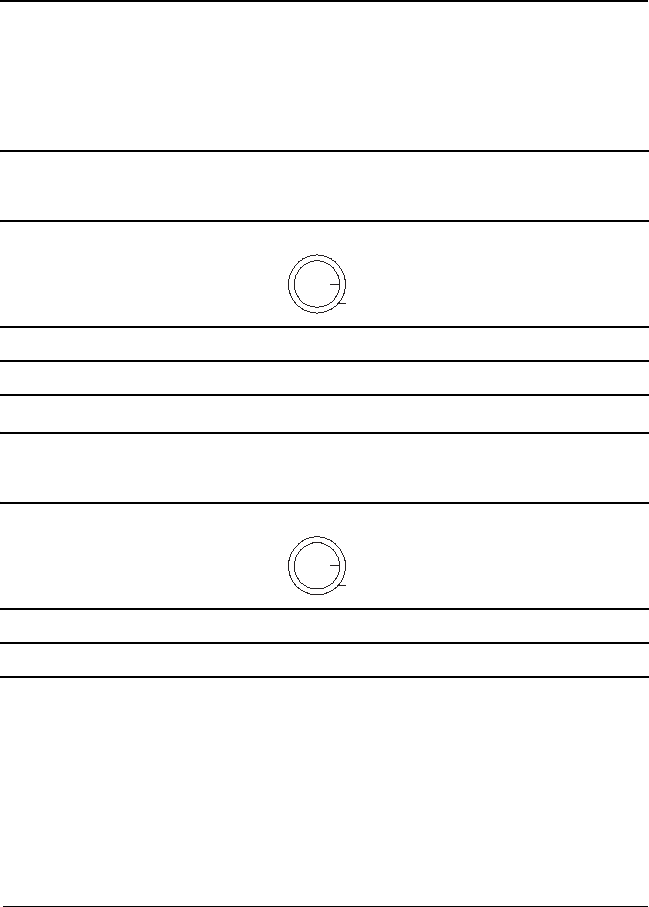
Maintenance and Service Guide A–1
A
Connector Pin Assignments
Table A-1
Stereo Speaker/Headphone
Pin Signal Pin Signal
1 Audio out 2 Ground
2
1
Table A-2
Microphone
Pin Signal Pin Signal
1 Audio in 2 Ground
2
1
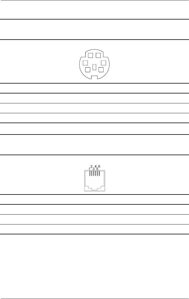
A–2 Maintenance and Service Guide
Connector Pin Assignments
Table A-3
Keyboard/Mouse
Pin Signal Pin Signal
1 Keyboard/mouse data1 4 +5 VDC
2 Keyboard/mouse data2 5 Keyboard/mouse clock1
3 Ground 6 Keyboard/mouse clock2
Table A-4
RJ-11 Modem
Pin Signal Pin Signal
1Unused 4Unused
2 Tip 5 Unused
3Ring 6Unused
KEY
65
43
2
1
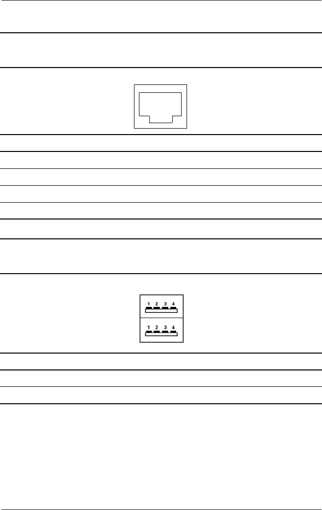
Connector Pin Assignments
Maintenance and Service Guide A–3
Table A-5
RJ-45 Network Interface
Pin Signal Pin Signal
1 Transmit + 5 Unused
2 Transmit - 6 Receive -
3 Receive + 7 Unused
4Unused 8Unused
Table A-6
Universal Serial Bus
Pin Signal Pin Signal
1 +5 VDC 3 Data +
2 Data - 4 Ground
6
5
4
3
2
178
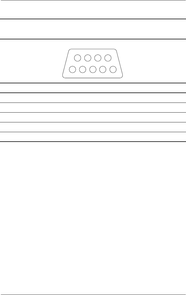
A–4 Maintenance and Service Guide
Connector Pin Assignments
Table A-7
Serial
Pin Signal Pin Signal
1 Carrier detect 6 Data set ready
2 Receive data 7 Ready to send
3 Transmit data 8 Clear to send
4 Data terminal ready 9 Ring indicator
5 Signal ground
1
69
5
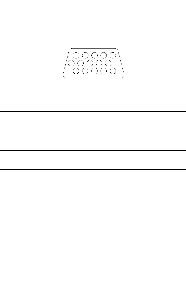
Connector Pin Assignments
Maintenance and Service Guide A–5
Table A-8
External Monitor
Pin Signal Pin Signal
1 Red analog 9 +5 VDC
2 Green analog 10 Ground
3 Blue analog 11 Monitor detect
4 Not connected 12 DDC 2B data
5 Ground 13 Horizontal sync
6 Ground analog 14 Vertical sync
7 Ground analog 15 DDC2B clock
8 Ground analog
1
6
11
5
10
15
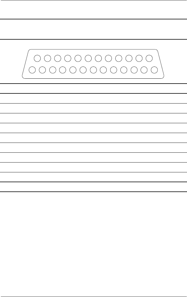
A–6 Maintenance and Service Guide
Connector Pin Assignments
Table A-9
Parallel
Pin Signal Pin Signal
1 Strobe* 10 Acknowledge*
2 Data bit 0 11 Busy
3 Data bit 1 12 Paper out
4 Data bit 2 13 Select
5 Data bit 3 14 Auto line feed*
6 Data bit 4 15 Error*
7 Data bit 5 16 Initialize printer*
8 Data bit 6 17 Select in*
9 Data bit 7 18–25 Signal ground
*Signal is active low.
1
14 25
13
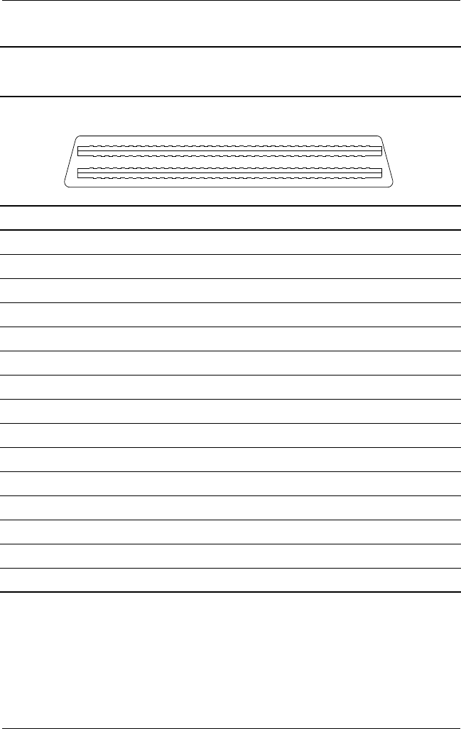
Connector Pin Assignments
Maintenance and Service Guide A–7
Table A-10
Docking
Pin Signal Pin Signal
1 EBOXL 16 RDATA
2AGND 17TRK0
3 EBOXS1 18 WDATA
4RED 19WGATE
5AGND 20STEP
6 GREEN 21 DIR
7 AGRD 22 POWER ON
8 BLUE 23 SYS RESET
9AGND 24GND
10 VSYNC 25 DSKCHG
11 HSYNC 26 +5 V (VDD)
12 DDC DAT 27 AUGND
13 DDC CLK 28 XA2/L IN
14 GND 29 XA3/R IN
15 INDEX 30 MID0/MIC IN
31
61
91
1
120
90
60
30

A–8 Maintenance and Service Guide
Connector Pin Assignments
Table A-10
Docking
(Continued)
Pin Signal Pin Signal
31 AUGND 46 SRDY
32 XA0/L OUT 47 EBOXS1/GND
33 XSD/MIC SN 48 RI1 EX
34 XA1/R OUT 49 GND
35 GND 50 SLCT LD0
36 GND 51 PE LD1
37 EXPCLK2 52 ACK LD2
38 +3.3 V 53 BUSY LD3
39 EXPCLK0 54 GND
40 +5 V (8051VCC) 55 STRB LD4
41 EXPLCK 56 ALF LD5
42 EBOXS2 57 INIT LD6
43 GND 58 SLCTIN LD7
44 EBOXL 59 GND
45 EBOXL/GND 60 PDATA0 LD8
31
61
91
1
120
90
60
30
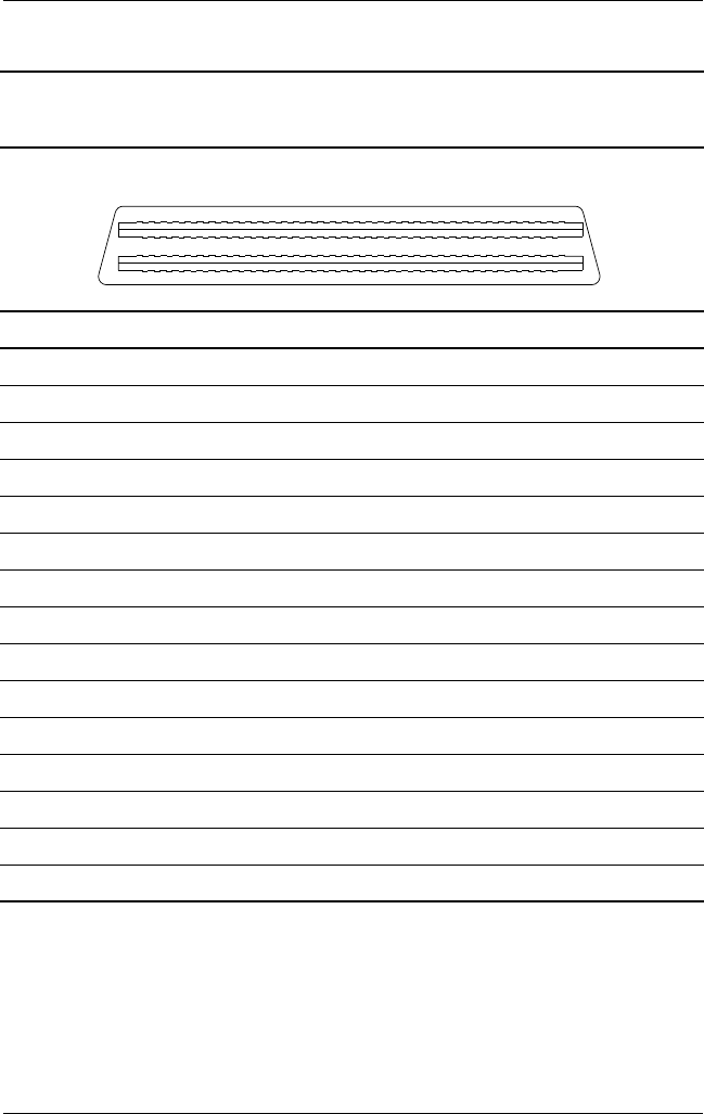
Connector Pin Assignments
Maintenance and Service Guide A–9
Table A-10
Docking
(Continued)
Pin Signal Pin Signal
61 PDATA1 LD9 76 DRT1 LIIC DAT
62 PDATA2 LD10 77 DSR1 EX
63 PDATA3 LD11 78 DCD1 EX
64 GND 79 12C DATA
65 PDATA4 LD12 80 GND
66 PDATA5 LD13 81 12C CLK
67 PDATA6 LD14 82 GND
68 PDATA7 LD 15 83 HDSEL
69 GND 84 GND
70 ERROR LCLK 85 WPROT
71 RXD1 LVREQ 86 EBOXS2/GND
72 TXD1 LCREQ 87 ERDY
73 RTS1 LEN 88 EBOXL/GND
74 GND 89 FLUSHREQ
75 CTS1 LIIC CLK 90 MEMACK
31
61
91
1
120
90
60
30
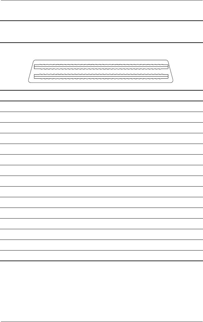
A–10 Maintenance and Service Guide
Connector Pin Assignments
Table A-10
Docking
(Continued)
Pin Signal Pin Signal
91 PS2 VCC 106 GND
92 SERIRQ 107 AD[15]
93 PS2 CLK 108 AD[13]
94 EXPREQ 109 AD[11]
95 AD[29] 110 AD[09]
96 AD[31] 111 GND
97 AD[30] 112 AD[06]
98 AD[28] 113 AD[04]
99 AD[26] 114 AD[02]
100 GND 115 AD[00]
101 AD[24] 116 GND
102 AD[22] 117 FRAME
103 AD[20] 118 TRDY
104 AD[18] 119 STOP
105 AD[16] 120 PAR
31
61
91
1
120
90
60
30

Maintenance and Service Guide B–1
B
Power Cord Set Requirements
3-Conductor Power Cord Set
The wide range input feature of the notebook permits it to operate
from any line voltage from 100 to 120 or 220 to 240 volts AC.
The power cord set received with the notebook meets the
requirements for use in the country where the equipment is
purchased.
Power cord sets for use in other countries must meet the
requirements of the country where the notebook is used. For more
information on power cord set requirements, contact a Compaq
authorized reseller or service provider.
General Requirements
The requirements listed below are applicable to all countries:
■The length of the power cord set must be at least 1.5 m
(5.00 feet) and a maximum of 2.0 m (6.50 feet).
■All power cord sets must be approved by an acceptable
accredited agency responsible for evaluation in the country
where the power cord set will be used.
■The power cord set must have a minimum current capacity
of 10 amperes and a nominal voltage rating of 125 or
250 volts AC, as required by each country’s power system.
■The appliance coupler must meet the mechanical
configuration of an EN 60 320/IEC 320 Standard Sheet C13
connector, for mating with the appliance inlet on the back of
the notebook.

B–2 Maintenance and Service Guide
Power Cord Set Requirements
Country-Specific Requirements
3-Conductor Power Cord Set Requirements
Country Accredited Agency Applicable Note Number
Australia EANSW 1
Austria OVE 1
Belgium CEBC 1
Canada CSA 2
Denmark DEMKO 1
Finland FIMKO 1
France UTE 1
Germany VDE 1
Italy IMQ 1
Japan METI 3
The Netherlands KEMA 1
Norway NEMKO 1
Sweden SEMKO 1
Switzerland SEV 1

Power Cord Set Requirements
Maintenance and Service Guide B–3
United Kingdom BSI 1
United States UL 2
Notes
1. The flexible cord must be <HAR> Type HO5VV-F, 3-conductor, 1.0 mm2
conductor size. The power cord set fittings (appliance coupler and wall plug)
must bear the certification mark of the agency responsible for evaluation in
the country where it will be used.
2. The flexible cord must be Type SPT-3 or equivalent, No. 18 AWG,
3-conductor. The wall plug must be a two-pole grounding type with a
NEMA 5-15P (15 A, 125 V) or NEMA 6-15P (15 A, 250 V) configuration.
3. The appliance coupler, flexible cord, and wall plug must bear a “T” mark and
registration number in accordance with the Japanese Dentori Law. The
flexible cord must be Type VCT or VCTF, 3-conductor, 1.00-mm2 conductor
size. The wall plug must be a two-pole grounding type with a Japanese
Industrial Standard C8303 (7 A, 125 V) configuration.
3-Conductor Power Cord Set Requirements
Country Accredited Agency Applicable Note Number

Maintenance and Service Guide C–1
C
Screw Listing
This appendix provides specification and reference information
for the screws used in the notebook. All screws listed in this
appendix are available in the Miscellaneous Screw Kit, spare part
number 241440-001.
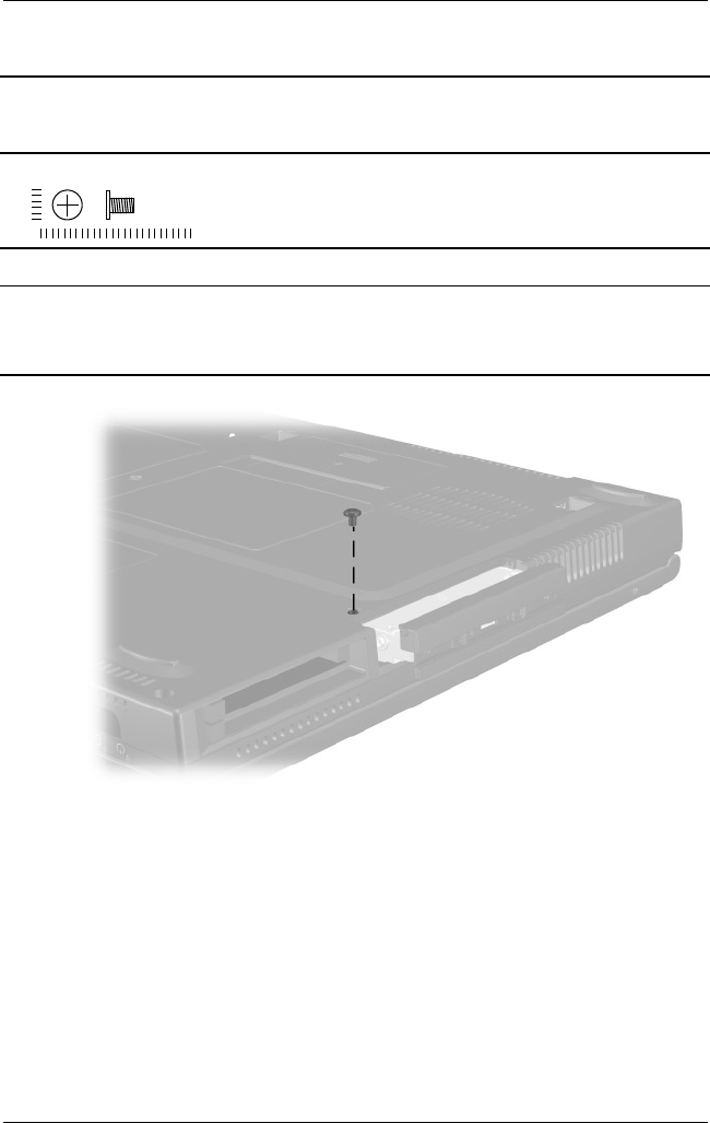
C–2 Maintenance and Service Guide
Figure C-1. PM2.5 × 2.5 Screw Location
Table C-1
Phillips Metric 2.5 × 2.5 Screw
Color Qty Length Thread
Head
Width
Black 1 4.0 mm 2.5 mm 5.0 mm
Where used:
One screw that secures the hard drive to the base enclosure
(documented in Section 5.3)
mm
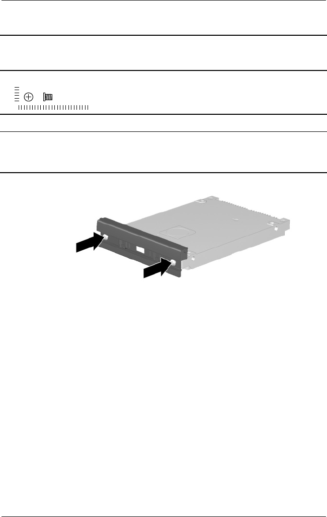
Maintenance and Service Guide C–3
Figure C-2. PM1.5 × 3.5 Screw Location
Table C-2
Phillips Metric 1.5 × 3.5 Screw
Color Qty Length Thread
Head
Width
Black 2 3.0 mm 2.0 mm 3.0 mm
Where used:
Two screws that secure the hard drive bezel to the hard drive
(documented in Section 5.3)
mm
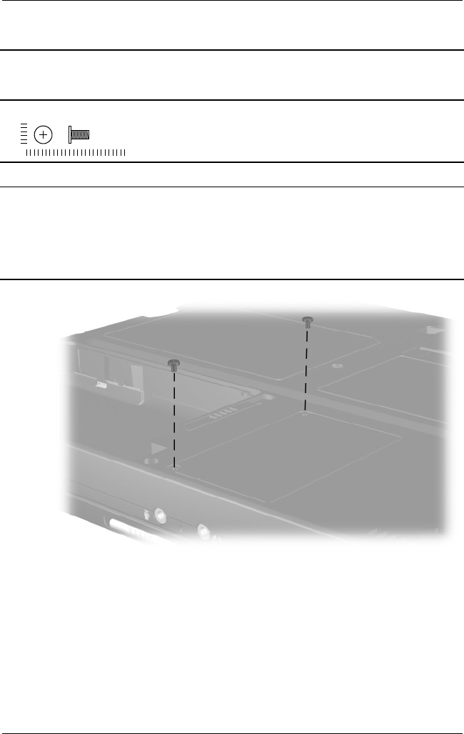
C–4 Maintenance and Service Guide
Figure C-3. PM2.5 × 5.5 Screw Location
Table C-3
Phillips Metric 2.5 × 5.0 Screw
Color Qty Length Thread
Head
Width
Black 3 5.0 mm 2.5 mm 4.5 mm
Where used:
Evo Notebook N600c models—Two screws that secure the memory
expansion compartment cover to the base enclosure
Evo Notebook N620c and N610c models—Two screws that secure the mini
PCI compartment cover to the base enclosure (documented in Section 5.5)
mm
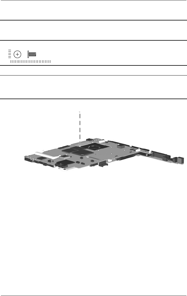
Maintenance and Service Guide C–5
Figure C-4. PM2.5 × 5.5 Screw Location
Table C-3
Phillips Metric 2.5 × 5.0 Screw
(Continued)
Color Qty Length Thread
Head
Width
Black 3 5.0 mm 2.5 mm 4.5 mm
Where used:
Evo Notebook N620c and N610c models—One screw that secures the fan to
the heat sink (documented in Section 5.14)
mm
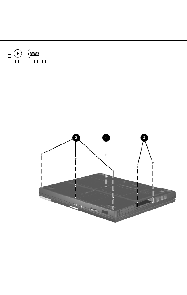
C–6 Maintenance and Service Guide
Figure C-5. TM2.5 × 7.0 Screw Locations
Table C-4
Torx T8 Metric 2.5 × 7.0 Screw
Color Qty Length Thread
Head
Width
Black 12 7.0 mm 2.5 mm 5.0 mm
Where used:
1 One screw that secures the keyboard to the base enclosure
(documented in Section 5.7)
2 Three screws that secure the top cover to the base enclosure
(documented in Section 5.12)
3 Evo Notebook N620c models—Two screws that secure the top cover to the
base enclosure in the hard drive bay (documented in Section 5.12)
mm
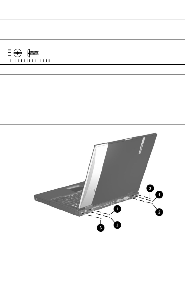
Maintenance and Service Guide C–7
Figure C-6. TM2.5 × 7.0 Screw Locations
Table C-4
Torx T8 Metric 2.5 × 7.0 Screw
(Continued)
Color Qty Length Thread
Head
Width
Black 12 7.0 mm 2.5 mm 5.0 mm
Where used:
1 Two screws that secure the switch cover to the base enclosure
(documented in Section 5.10)
2 Two screws that secure the display to the base enclosure
(documented in Section 5.11)
3 Evo Notebook N620c and N610c models—Two screws that secure the top
cover to the base enclosure (documented in Section 5.12)
mm
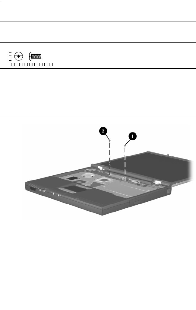
C–8 Maintenance and Service Guide
Figure C-7. TM2.5 × 7.0 Screw Locations
Table C-4
Torx T8 Metric 2.5 × 7.0 Screw
(Continued)
Color Qty Length Thread
Head
Width
Black 12 7.0 mm 2.5 mm 5.0 mm
Where used:
1 One screw that secures the display ground cable to the base enclosure
(documented in Section 5.11)
2 Evo Notebook N620c and N610c models—One screw that secures the top
cover to the base enclosure (documented in Section 5.12)
mm
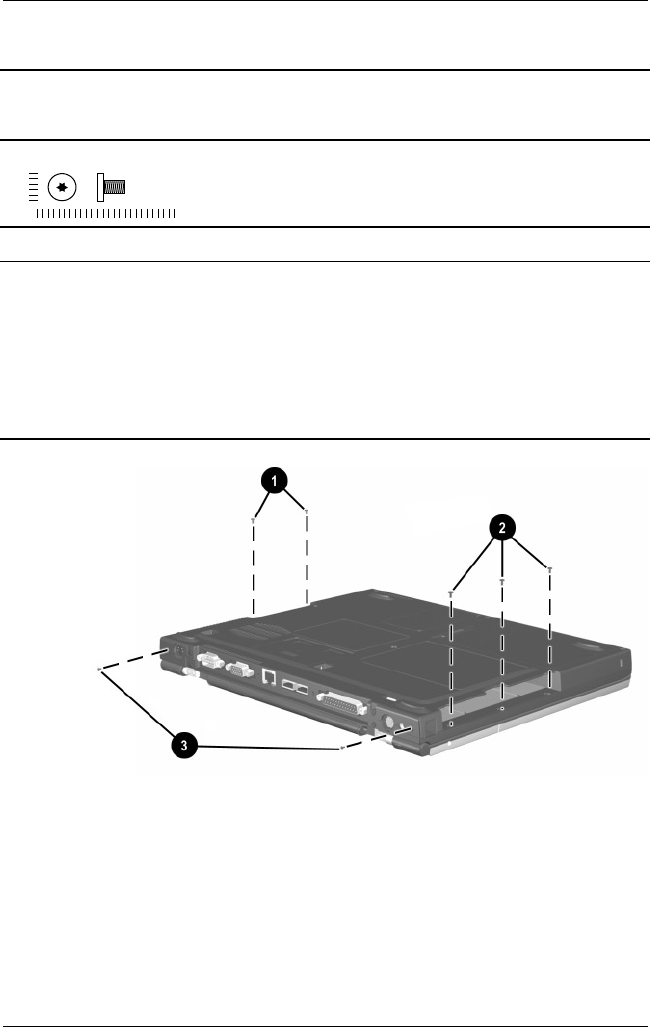
Maintenance and Service Guide C–9
Figure C-8. TM2.5 × 5.0 Screw Locations
Table C-5
Torx T8 Metric 2.5 × 5.0 Screw
Color Qty Length Thread
Head
Width
Black 12 5.0 mm 2.5 mm 4.0 mm
Where used:
1 Evo Notebook N600c models—Two screws that secure the top cover to the
base enclosure in the hard drive bay (documented in Section 5.12)
2 Three screws that secure the top cover to the base enclosure in the
Media Bay (documented in Section 5.12)
3 Evo Notebook N600c models—Two screws that secure the top cover to the
base enclosure (documented in Section 5.12)
mm
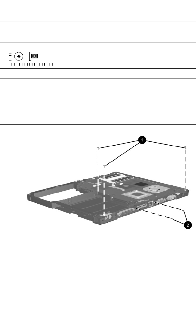
C–10 Maintenance and Service Guide
Figure C-9. TM2.5 × 5.0 Screw Locations
Table C-5
Torx T8 M2.5 × 5.0 Screw
(Continued)
Color Qty Length Thread
Head
Width
Black 12 5.0 mm 2.5 mm 4.0 mm
Where used:
1 Three screws that secure the system board to the base enclosure
(documented in Section 5.13)
2 Evo Notebook N620c and N610c models only—Two screws that secure
the system board to the base enclosure through the rear panel
(documented in Section 5.13)
mm
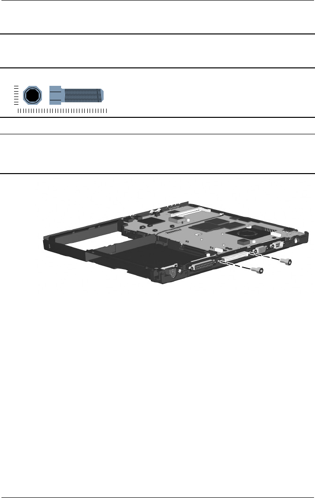
Maintenance and Service Guide C–11
Figure C-10. 7.0 × 20.0 Bushing Guide Location
Table C-6
7.0 mm × 20.0 mm Bushing Guide
Color Qty Length Thread
Head
Width
Silver 2 20 mm n/a 7.0 mm
Where used:
Evo Notebook N600c models only—Two bushing guides that secure the
system board to the base enclosure (documented in Section 5.13)
mm
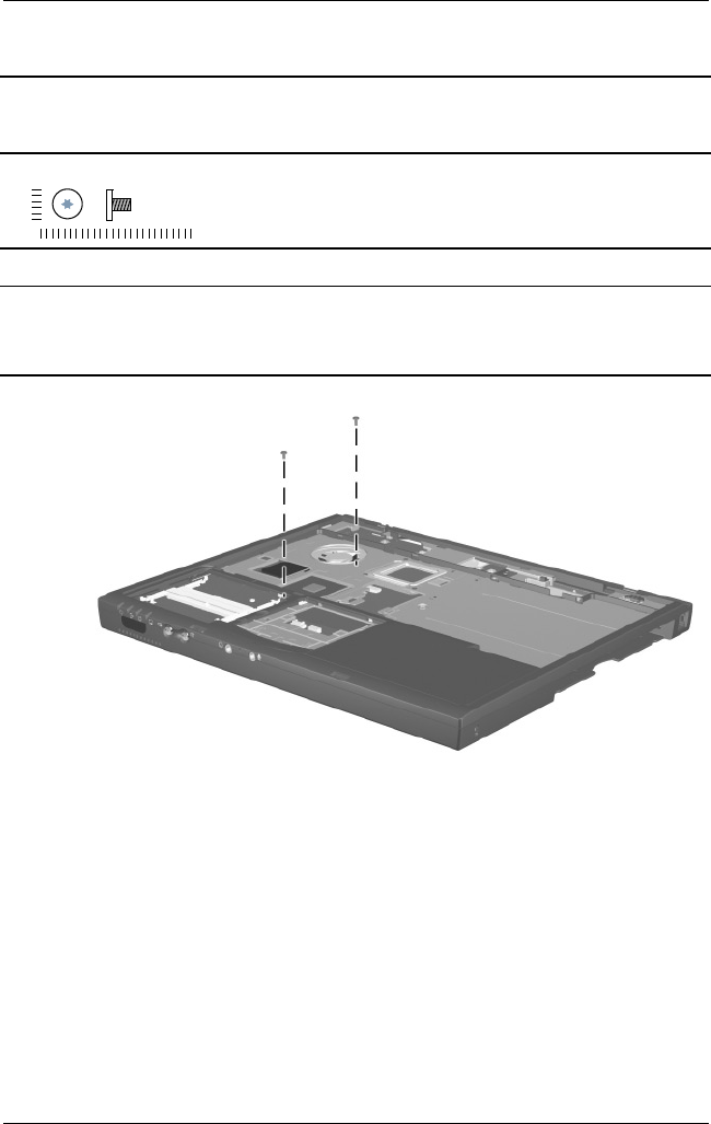
C–12 Maintenance and Service Guide
Figure C-11. TM2.0 × 4.0 Screw Location
Table C-7
Torx Metric 2.0 × 3.0 Screw
Color Qty Length Thread
Head
Width
Silver 2 3.0 mm 2.0 mm 5.0 mm
Where used:
Evo Notebook N620c and N610c models—Two screws that secures the top
cover to the system board (documented in Section 5.12)
mm
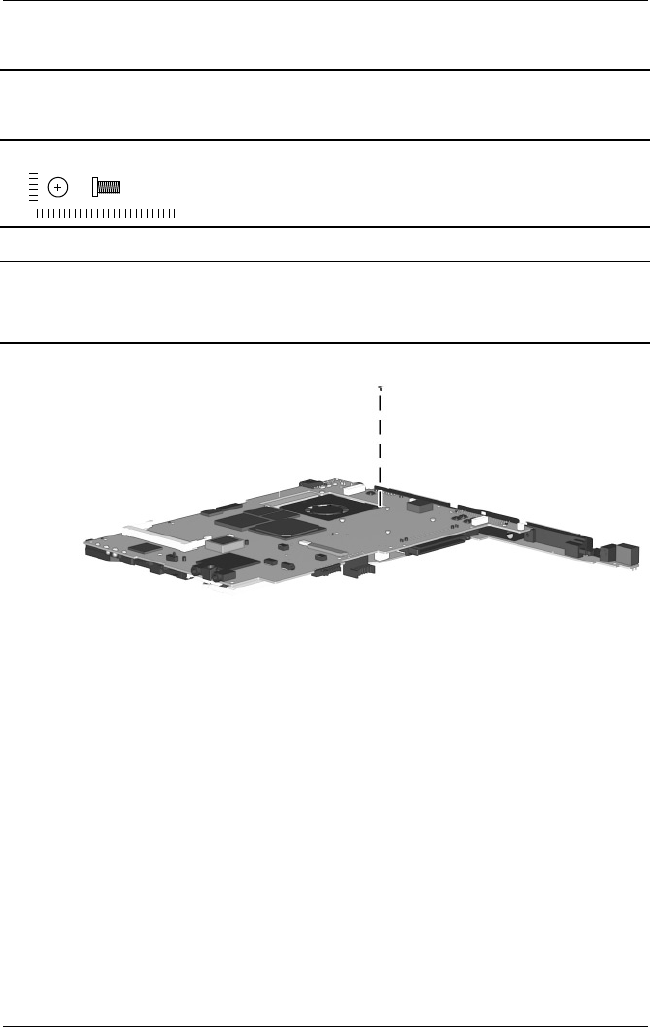
Maintenance and Service Guide C–13
Figure C-12. PM2.0 × 4.0 Screw Location
Table C-8
Phillips Metric 2.0 × 4.0 Screw
Color Qty Length Thread
Head
Width
Black 11 4.0 mm 2.0 mm 3.5 mm
Where used:
Evo Notebook N600c models only—One screw that secures the fan to the
system board (documented in Section 5.14)
mm
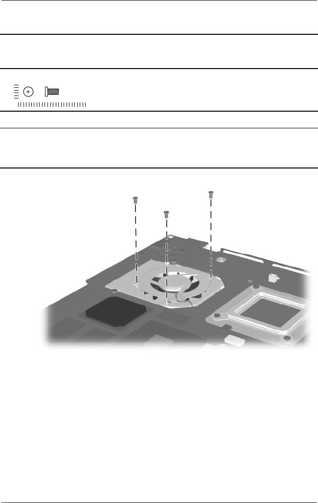
C–14 Maintenance and Service Guide
Figure C-13. PM2.0 × 4.0 Screw Location (Continued)
Table C-8
Phillips M2.0 × 4.0 Screw
(Continued)
Color Qty Length Thread
Head
Width
Black 11 4.0 mm 2.0 mm 3.5 mm
Where used:
Evo Notebook N620c and N610c models only—Three screws that secure
the fan to the system board (documented in Section 5.14)
mm
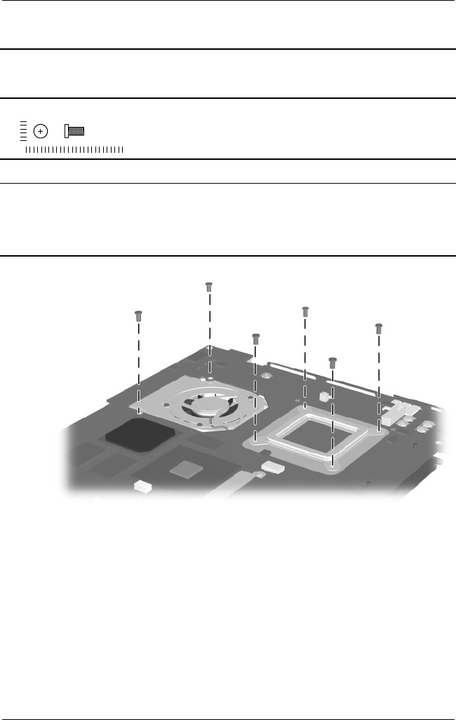
Maintenance and Service Guide C–15
Figure C-14. PM2.0 × 4.0 Screw Location (Continued)
Table C-8
Phillips M2.0 × 4.0 Screw
(Continued)
Color Qty Length Thread
Head
Width
Black 11 4.0 mm 2.0 mm 3.5 mm
Where used:
Evo Notebook N620c and N610c models only—Six screws that secure the
heat sink and processor mounting bracket to the system board
(documented in Section 5.15)
mm

Maintenance and Service Guide Index–1
Index
A
AC adapter
spare part numbers 3–22
specifications 6–10
audio troubleshooting 2–25
B
base enclosure, spare part
numbers 3–11
battery components
compartment 1–40, 1–42
light 1–30
pack, removing 5–4
pack, spare part numbers
3–13
release latch 1–40, 1–42,
5–5
spare part numbers 5–4
specifications 6–10
Bluetooth wireless
communication MultiPort
module, spare part number
3–22
C
cables, service considerations
4–2
caps lock key 1–36
caps lock light 1–38
CD-ROM drive
OS loading problems 2–24
spare part number 3–15,
3–21, 5–6
specifications 6–7
CD-RW drive
spare part number 3–15,
3–21, 5–6
specifications 6–9
Certificate of Authenticity
label 1–42
components
front 1–30
keyboard 1–36
left side 1–32, 1–34
rear panel 1–32, 1–34
right side 1–30
top 1–37
Computer Setup
Advanced Menu 2–5
File Menu 2–3
Security Menu 2–4
computer specifications 6–1
connector pin assignments
headphone jack A–1
keyboard connector A–2
microphone jack A–1
modem jack A–2
monitor connector A–5
mouse connector A–2

Index–2 Maintenance and Service Guide
Index
network interface jack A–3
parallel connector A–6
RJ-11 jack A–2
RJ-45 jack A–3
serial connector A–4
speaker jack A–1
universal serial bus (USB)
connector A–3
connectors, service
considerations 4–2
cursor control keys 1–36
D
DC power jack 1–34
DC-DC converter board
removing 5–52
spare part numbers 3–11,
5–52
diagnostics
configuration information
2–7
test information 2–8
diskette drive
light 1–31
OS loading problems 2–23
spare part number 3–15,
3–19, 3–21, 5–6
specifications 6–6
display
release latch 1–31
removing 5–29
spare part numbers 3–3,
5–29
specifications 6–3
DMA specifications 6–11
docking connector 1–35, 1–40
docking recess latch 1–42
docking station,
troubleshooting 2–18
drive activity light 1–30
drives, preventing damage 4–2
DVD/CD-RW combination
drive, spare part number
3–15, 3–21, 5–6
DVD-ROM drive
OS loading problems 2–24
spare part number 3–15,
3–21, 5–6
specifications 6–8
E
Easy Access buttons 1–38
electrostatic discharge 4–3,
4–7
embedded numeric keypad
1–36
external monitor connector
1–33, 1–35
F
fan 1–42
location 1–40
removing 5–42
spare part number 3–9,
5–42
feet
illustrated 3–16
locations 5–11
Fn key 1–36
front components 1–30
function keys 1–36

Index
Maintenance and Service Guide Index–3
G
grounding equipment and
methods 4–5
H
hard drive
location 1–33, 1–35, 1–40
OS loading problems 2–20
removing 5–8
security screw 1–40
spare part numbers 3–13,
3–19, 5–8
specifications 6–4
hard drive bezel
illustrated 3–16
removing 5–10
hard drive security screw 1–42
headphone jack
location 1–31
pin assignments A–1
heat sink
removing 5–46
spare part number 3–11,
5–46
I
I/O address specifications
6–13
illustrated parts catalog 3–1
infrared port 1–31
interrupt specifications 6–12
IOmega ZIP drive, spare part
number 3–15, 3–21, 5–6
K
keyboard
components 1–36
removing 5–17
spare part numbers 3–3,
3–5, 5–17
troubleshooting 2–28
keyboard connector
location 1–32, 1–35
pin assignments A–2
L
left side components 1–32,
1–34
Logo Kit, spare part number
3–22
M
mass storage devices 3–18
Media Bay 1–41
location 1–31, 1–39
release latch 1–39
Media Bay device
removing 5–7
spare part numbers 3–15,
3–21, 5–6
Media Bay release latch 1–41,
5–7
Media Bay space saver 3–16
memory expansion board
removing 5–22
spare part numbers 3–9,
5–22
memory expansion
compartment cover
illustrated 3–16
location 1–42

Index–4 Maintenance and Service Guide
Index
memory map specifications
6–16
microphone jack
location 1–31
pin assignments A–1
mini PCI communications
board
removing 5–12
spare part numbers 3–13,
5–12
mini PCI compartment cover
illustrated 3–16
location 1–40
removing 5–13
Miscellaneous Plastics Kit
components 3–16
spare part number 3–7,
3–17
models 1–2
modem
removing 5–12
spare part numbers 3–13,
3–22, 5–12
troubleshooting 2–30
modem adapter, spare part
numbers 3–22
modem cable
illustrated 3–16
removing 5–54
routing 5–56
spare part number 3–22
modem cable adapter, spare
part numbers 3–22
modem jack, pin assignments
A–2
modem/NIC cover
illustrated 3–16
removing 5–13, 5–23
monitor connector
location 1–33, 1–35
pin assignments A–5
mouse connector
location 1–32, 1–35
pin assignments A–2
MultiPort 1–34
MultiPort module
cover, illustrated 3–16
N
network interface card (NIC)
removing 5–12
spare part numbers 3–13,
5–12
network, troubleshooting 2–30
nonfunctioning device,
troubleshooting 2–18, 2–27
num lock light 1–37
numeric keypad, embedded
1–36
O
operating system loading,
troubleshooting 2–19
optical device, spare part
numbers 3–21, 5–6
P
packing precautions 4–4
parallel connector
location 1–33, 1–35
pin assignments A–6
password, clearing 1–28

Index
Maintenance and Service Guide Index–5
PC Card eject button 1–33,
1–35
PC Card slot 1–33, 1–35
PC Card slot space savers 3–16
plastic parts 4–2
pointing device,
troubleshooting 2–29
pointing stick 1–38
pointing stick button 1–38
power cord
3-conductor set B–1
country-specific
requirements B–2
general requirements B–1
set requirements B–1
spare part numbers 3–23
power jack 1–32
power light 1–30
power management features
1–29
power switch 1–38
power, troubleshooting 2–12
processor
removing 5–50
spare part numbers 5–50
processor mounting bracket
illustrated 3–16
removing 5–48
R
real time clock (RTC) battery
illustrated 3–16
removing 5–15
rear panel components 1–32,
1–34
removal and replacement
preliminaries 4–1
removal and replacement
procedures 5–1
right side components 1–30
RJ-11 jack
location 1–31
pin assignments A–2
RJ-11 jack cover 3–16
RJ-11 P55 adapter, spare part
numbers 3–23
RJ-11 PTT adapter, spare part
number 3–23
RJ-45 jack
location 1–33, 1–35
pin assignments A–3
RJ-45 network cable, spare
part number 3–23
ROM, system 5–16
S
Screw Kit
components C–1
spare part number 3–23
screw listing C–1
scroll lock light 1–37
security cable slot 1–31
serial connector
location 1–33, 1–35
pin assignments A–4
serial number 1–40, 1–42, 3–1
service considerations 4–1
speaker jack, pin assignments
A–1

Index–6 Maintenance and Service Guide
Index
speakers
disconnecting 5–28
location 1–38
specifications
AC adapter 6–10
battery 6–10
CD-ROM drive 6–7
CD-RW drive 6–9
computer 6–1
diskette drive 6–6
display 6–3
DMA 6–11
DVD-ROM drive 6–8
hard drive 6–4
I/O addresses 6–13
interrupts 6–12
memory map 6–16
Standby button 1–38
static shielding materials 4–7
stereo line-out jack 1–31
SuperDisk LS120 drive, spare
part number 3–15, 3–21, 5–6
S-Video connector 1–33, 1–35
switch cover
removing 5–27
spare part number 3–3,
5–27
system board
removing 5–35
spare part numbers 3–11,
5–35
system memory map 6–16
system ROM 5–15
T
tools required 4–1
top components 1–37
top cover
removing 5–32
spare part numbers 3–9,
5–32
TouchPad 1–38
removing 5–25
spare part numbers 3–7,
5–25
TouchPad button 1–38
transporting precautions 4–4
troubleshooting
audio 2–25
Computer Setup 2–2
docking station 2–18
keyboard 2–28
modem 2–30
network 2–30
nonfunctioning device
2–18, 2–27
operating system loading
2–19
overview 2–1
pointing device 2–29
power 2–12
video 2–16
U
universal serial bus (USB)
connector
location 1–33, 1–35
pin assignments A–3

