Compex Systems 08-WLM54GP30 WIRELESS-G 30DBM NETWORK MINI PCI ADAPTER User Manual wlm54gp30
Compex Systems Pte Ltd WIRELESS-G 30DBM NETWORK MINI PCI ADAPTER wlm54gp30
Users manual
IWAVEPORT WLM54GP30
USER MANUAL

© Copyright 2007 Compex Systems Pte Ltd
All Rights Reserved
This document contains information, which is protected by copyright.
Reproduction, adaptation or translation without prior permission is prohibited,
except as allowed under the copyright laws.
Trademark Information
Compex® is a registered trademarks of Compex, Inc. Microsoft Windows and
the Windows logo are the trademarks of Microsoft Corp. NetWare is the
registered trademark of Novell Inc. All other brand and product names are
trademarks or registered trademarks of their respective owners.
Notice: Copyrights © 2007 by Compex, Inc. All rights reserved. Reproduction,
adaptation, or translation without prior permission of Compex, Inc. is prohibited,
except as allowed under the copyright laws.
Manual Revision by Daniel
Manual Number: U-0539-V1.8C Version 1.8, May 2007
Disclaimer
Compex, Inc. provides this manual without warranty of any kind, expressed or
implied, including but not limited to the implied warranties of merchantability
and fitness for a particular purpose. Compex, Inc. may make improvements
and/or changes to the product and/or specifications of the product described
in this manual, without prior notice. Compex, Inc will not be liable for any
technical inaccuracies or typographical errors found in this guide. Changes are
periodically made to the information contained herein and will be
incorporated into later versions of the manual. The information contained is
subject to change without prior notice.
Your Feedback
We value your feedback. If you find any errors in this user’s manual, or if you
have suggestions on improving, we would like to hear from you. Please contact
us at:
Fax: (65) 62809947
Email: feedback@compex.com.sg

FCC NOTICE
This device has been tested and found to comply with the limits for a Class B
digital device, pursuant to Part 15 of the FCC Rules. These limits are designed to
provide reasonable protection against harmful interference in a residential
installation. This device generates, uses and can radiate radio frequency
energy and, if not installed and used in accordance with the instructions, may
cause harmful interference to radio communications. However, there is no
guarantee that interference will not occur in a particular installation. If this
device does cause harmful interference to radio or television reception, the
user is encouraged to try to correct the interference by one or more of the
following measures:
• Reorient or relocate the receiving antenna.
• Connect the computer into an outlet on a circuit different from that to
which the receiver is connected.
• Increase the separation between the computer and receiver.
• Consult the dealer or an experienced radio/TV technician for help.
Caution: Any changes or modifications not expressly approved by the grantee
of this device could void the user's authority to operate the equipment.
FCC Compliance Statement: This device complies with Part 15 of the FCC Rules.
Operation is subject to the following two conditions:
1. This device may not cause harmful interference, and
2. This device must accept any interference received, including interference
that may cause undesired operation.
This device must accept any interference received, including interference that
may cause undesired operation.
IEEE 802.11b or 802.11g operation of this product in the U.S.A. is firmware-limited
to channels 1 through 11.
RF exposure warning
The equipment complies with FCC RF exposure limits set forth for an
uncontrolled environment.
The equipment must not be co-located or operating in conjunction with any
other antenna or transmitter.
End Product Labeling
The final end product must be labeled in a visible area with the following:
“Contains FCC ID: TK4-08-WLM54GP30”
ICES 003 Statement
This Class B digital apparatus complies with Canadian ICES-003.
Declaration of Conformity
Compex, Inc. declares the following:
Product Name: Compex Wireless Mini-PCI Network Adapter
Model No.: Compex iWavePort WLM54GP30 conforms to the following Product
Standards:
Radiated Emission Standards:
ETSI EN 300 328-2: July 2000; FCC: 47 CFR Part 15, Subpart B, ANSI C63.4-1992; 47
CFR Part 15, Subpart C (Section 15.247), ANSI C63.4-1992.
Conducted Emission Standards:
ETS 300 826: Nov. 1997.
Immunity Standards:
IEC 801-2; IEC 801-3; IEC 801-4
Low Voltage Directive:
EN 60 950:1992+A1: 1993+A2: 1993+A3; 1995+A4; 1996+A11: 1997
Therefore, this product is in conformity with the following regional standards:
FCC Class B ⎯ following the provisions of FCC Part 15 directive; CE Mark ⎯
following the provisions of the EC directive.
This Class B digital apparatus complies with Canadian ICES-003.
Technical Support Information
The warranty information and registration form are found in the Quick Install
Guide.
For technical support, you may contact Compex or its subsidiaries. For your
convenience, you may also seek technical assistance from the local distributor,
or from the authorized dealer/reseller that you have purchased this product
from. For technical support by email, write to support@compex.com.sg.
Refer to the table below for the nearest Technical Support Centers:
Technical Support Centers
Contact the technical support center that services your location.
U.S.A., Canada, Latin America and South America
Write
Compex, Inc.
840 Columbia Street, Suite B,
Brea, CA92821, USA
Call
Fax
Tel:
Tel:
Fax:
+1 (714) 482-0333 (8 a.m.-5 p.m. Pacific time)
+1 (800) 279-8891 (Ext.122 Technical Support)
+1 (714) 482-0332
Asia, Australia, New Zealand, Middle East and the rest of the World
Write
Compex Systems Pte Ltd
135, Joo Seng Road #08-01, PM Industrial Building
Singapore 368363
Call
Fax
Tel:
Tel:
Fax:
(65) 6286-1805 (8 a.m.-5 p.m. local time)
(65) 6286-2086 (Ext.199 Technical Support)
(65) 6283-8337
Internet
access/
E-mail:
FTPsite:
support@compex.com.sg
Ftp.compex.com.sg
Website: http://www.cpx.com or http://www.compex.com.sg
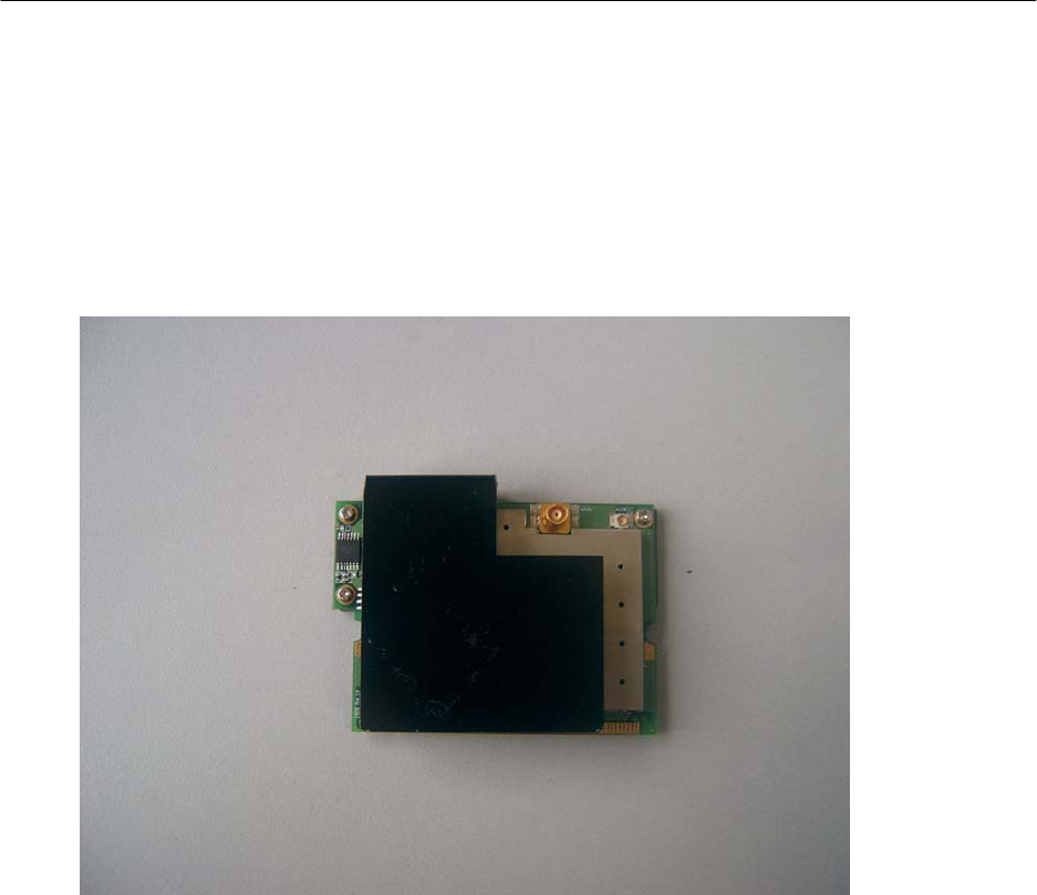
Product Overview
·Introduction
Thank you for purchasing this Wireless Network Adapter. Data security is
facilitated with WPA, IEEE 802.1x Authentication and 64-bit, 128-bit and 152-bit
WEP (Wired Equivalent Privacy). They support easy Plug and Play installation
and combine simplicity, data privacy, and reliability for your wireless network.
Chapter 1 Basic Setup
This chapter outlines the basic requirement for the installation and configuration
of the network adapter.
This network adapter is a plug-and-play device. You can plug it into the PCI slot
of your PC for auto-detection.
1.1 Hardware Installation
1. Turn off your PC and switch off the power from the main power
supply.
2. Remove the back cover of the PC.
3. Then insert the network adapter into your PCI slot as shown below.
Ensure that the network adapter is properly seated into the slot.
4. Replace the back cover.
5. Power on your PC.
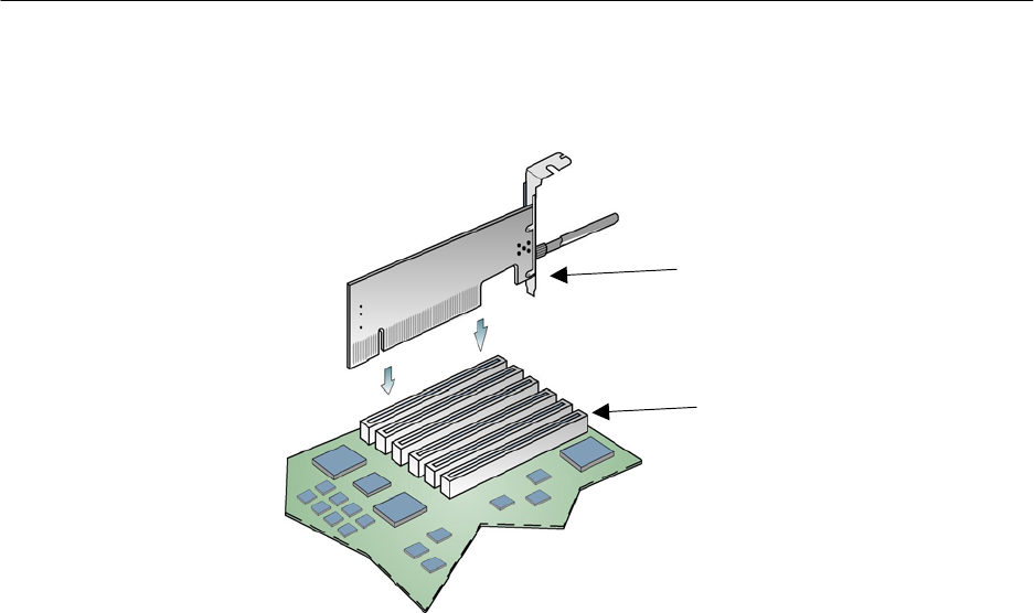
WLM54AG
PCI slot
1.2 Driver & Utility Installation
1. Insert the Product CD into your computer CD-ROM drive.
2. Click on Driver & Utility section and the system will run the setup.exe
automatically.
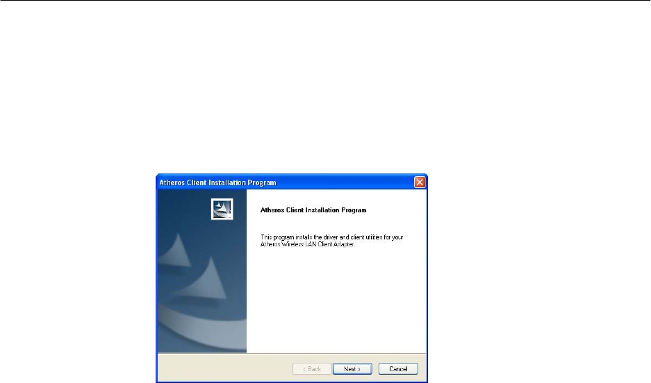
3. Next, the Atheros Client Installation Program screen appears. Click
on the Next> button to proceed.
4. When the License Agreement screen appears, you are required to
read and accept the agreement to continue. Click on the Next>
button to proceed.
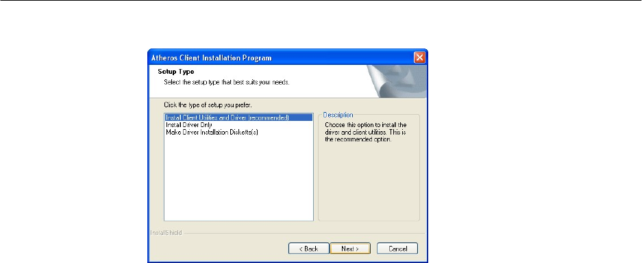
5. Select your preferred setup:
Install Client Utilities and Driver (Recommended) option
You are recommended to select this setup type. This option will
install both the driver and utility that support your PCI adapter.
Install Driver Only option (For Windows XP user only)
Select this option if you are going to use the Wireless Zero
Configuration Utility to configure your PCI adapter. Note that only
Windows XP comes with the Wireless Zero Configuration Utility.
Make Driver Installation Diskette(s)
Select this option if you wish to make a duplicate copy of the driver
and store to the diskette/s.
6. Click on the Next> button and follow the instructions stated on the
screen.
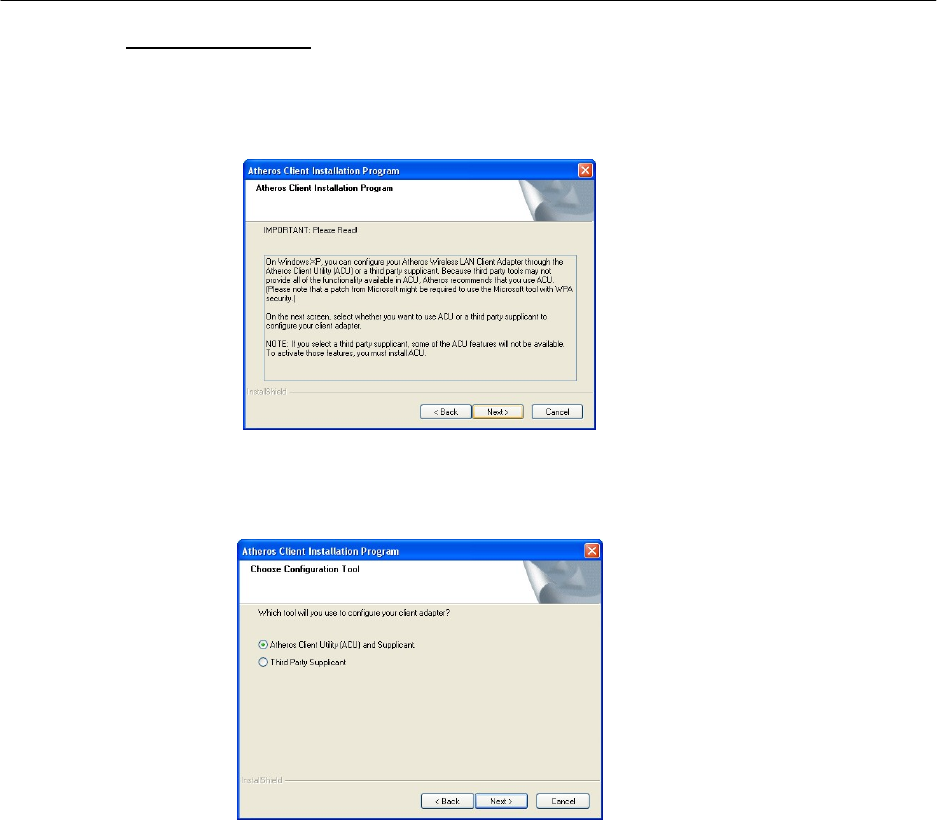
For Windows XP users
7. If you are using Windows XP as operating system, the following
screen will appear. Read the notice carefully and click on the Next>
button to proceed.
8. Select your choice of tool to assist you in configuring your adapter.
Click on the Next> button to proceed.
Atheros Client Utility (ACU) and Supplicant option
Select this option to install your network adapter. (Recommended)
Third Party Supplicant option
Select this option if you decide to use Wireless Zero Configuration
Utility to configure your wireless device. Installing this tool will only
allow you to view the status of the connected wireless device/s
through the utility; configuration using the utility will not be allowed.
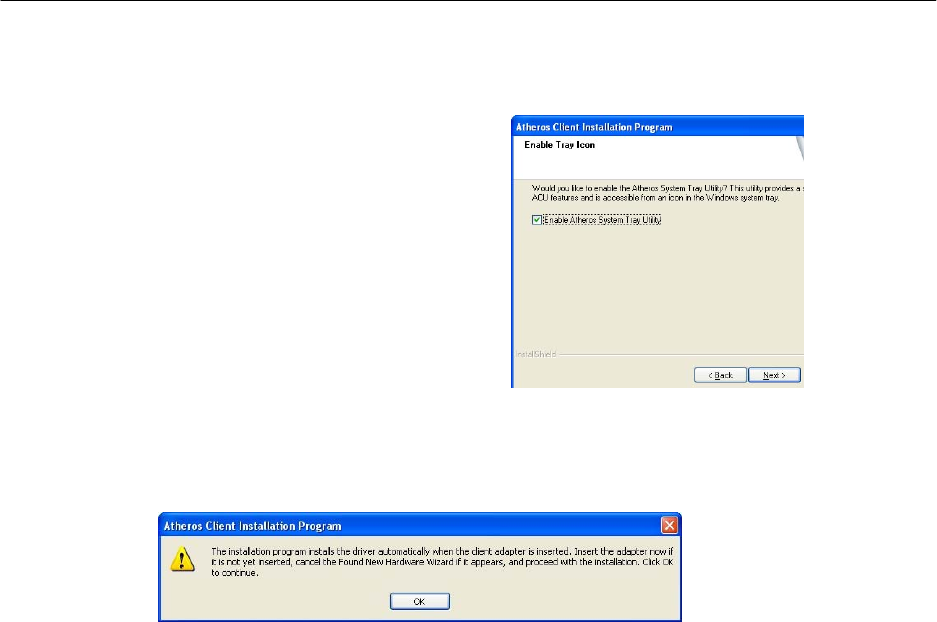
If you have selected Third Party Supplicant configuration tool, a
screen similar to that below will appear, prompting you to
enable/disable the system tray icon.
9. Click on the checkbox besides
Enable Atheros System Tray Utility
and click on the Next> button to
proceed.
10. The screen below appears to inform you that the driver will be
automatically installed if you have already inserted your client
adapter into the PCI slot of your computer.
Cancel the Found New Hardware Wizard if it appears and click on
the OK button to begin the installation.
11. If a similar screen similar to the one shown below appears, click on
the Continue Anyway button to continue the installation.
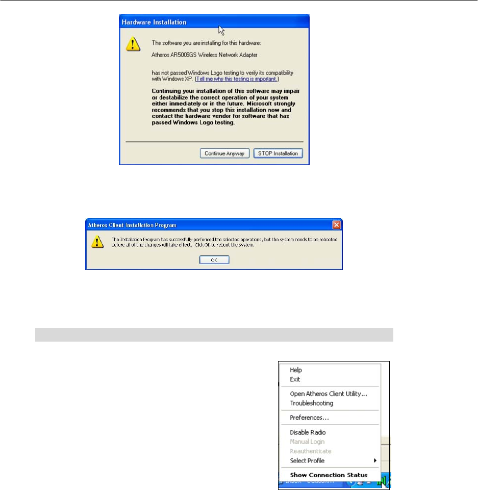
12. Click on the OK button to reboot your system and this will complete
the installation.
Chapter 2 Using the System Tray Utility
This chapter will elaborate on the Atheros system
tray utility found at the right bottom corner of your
screen. Right click on the utility icon and the menu
will appear.
The following explains the different options available on the menu:
Help
Open the online help.
Exit
Exit the Atheros Client Utility application. Once you exit, the icon will disappear
from the system tray.
Open Atheros Client Utility…
Launch the Client Utility.
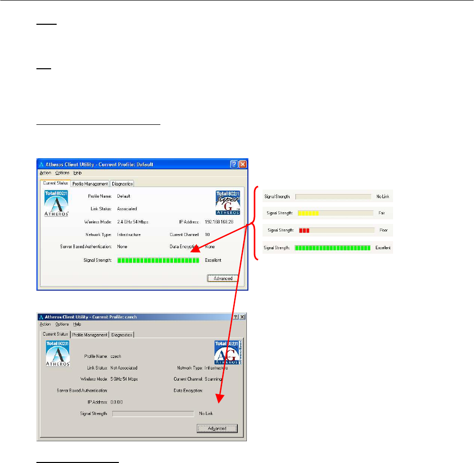
Wireless-G Excellent Signal Strength Example
Wireless-AG No Link Example
Manual LEAP Login
If you select this option, you will have to manually start the LEAP authentication
process to login to the network instead of being prompted for your LEAP
username and password during your windows logon.
Different signal strength indications
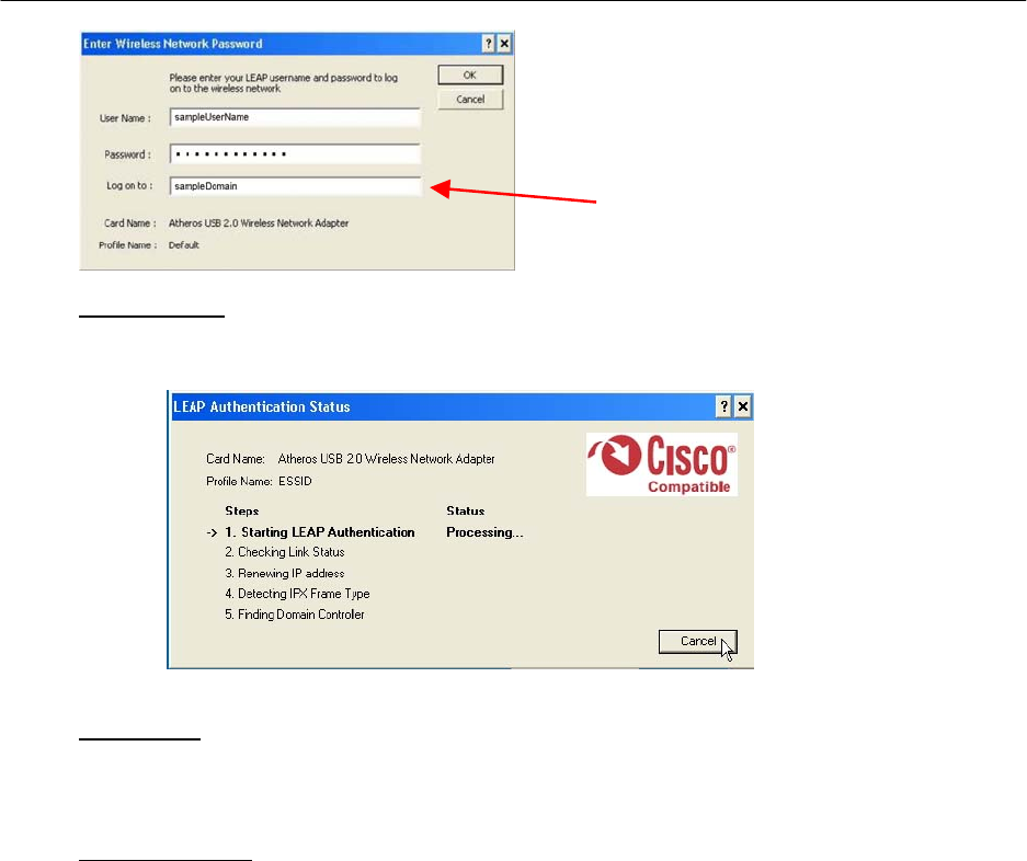
Reauthenticate
Reauthenticate to a LEAP-configured access point each time you login to a
LEAP network.
Select Profile
Click on a configuration profile name to switch to a particular wireless network.
If no configuration profile exists, you will need to add a profile first.
Connection Status
To view the connection status of your wireless PCI adapter.
Alternatively, you may also double click on the utility icon in the system tray.
Active Profile Displays the name of the active configuration profile.
Auto Profile Selection Shows whether auto profile selection is enabled.
Connection Status Displays whether the adapter is connected to a
wireless network.

Link Quality States the quality of the link connection.
SSID Displays the SSID of the network to which the
network adapter is associated.
Access Point Name Shows the name of the access point the wireless
adapter is connected to (if any).
Access Point IP Address Shows the IP address of the access point the wireless
adapter is connected to (if any).
Current Receive Rate Displays the data rate at which the wireless adapter
is currently receiving from the wireless network.
Current Transmit Rate Displays the data rate at which the wireless adapter
is currently transmitting to the wireless network.
Link Speed States the speed of the link connection.
Client Adapter IP Address Displays the IP address of the wireless adapter.
Chapter 3 Utility Features
This chapter shows you how to make use of the utility to view the status of your
wireless connection, to change your settings and also to monitor your wireless
performance via the network statistics.
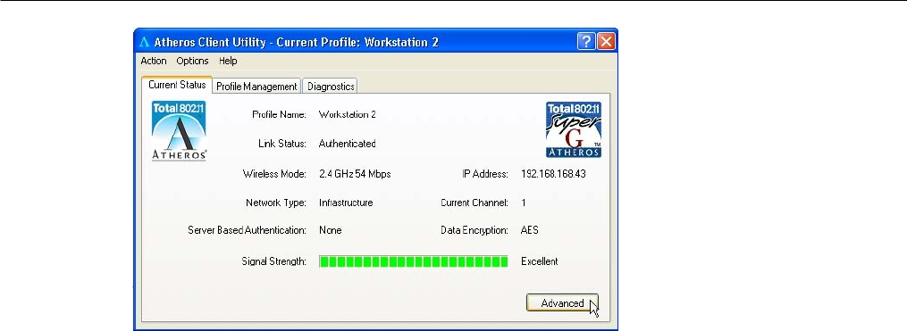
3.1 Current Status Tab
Displays the performance of the network adapter in the wireless network.
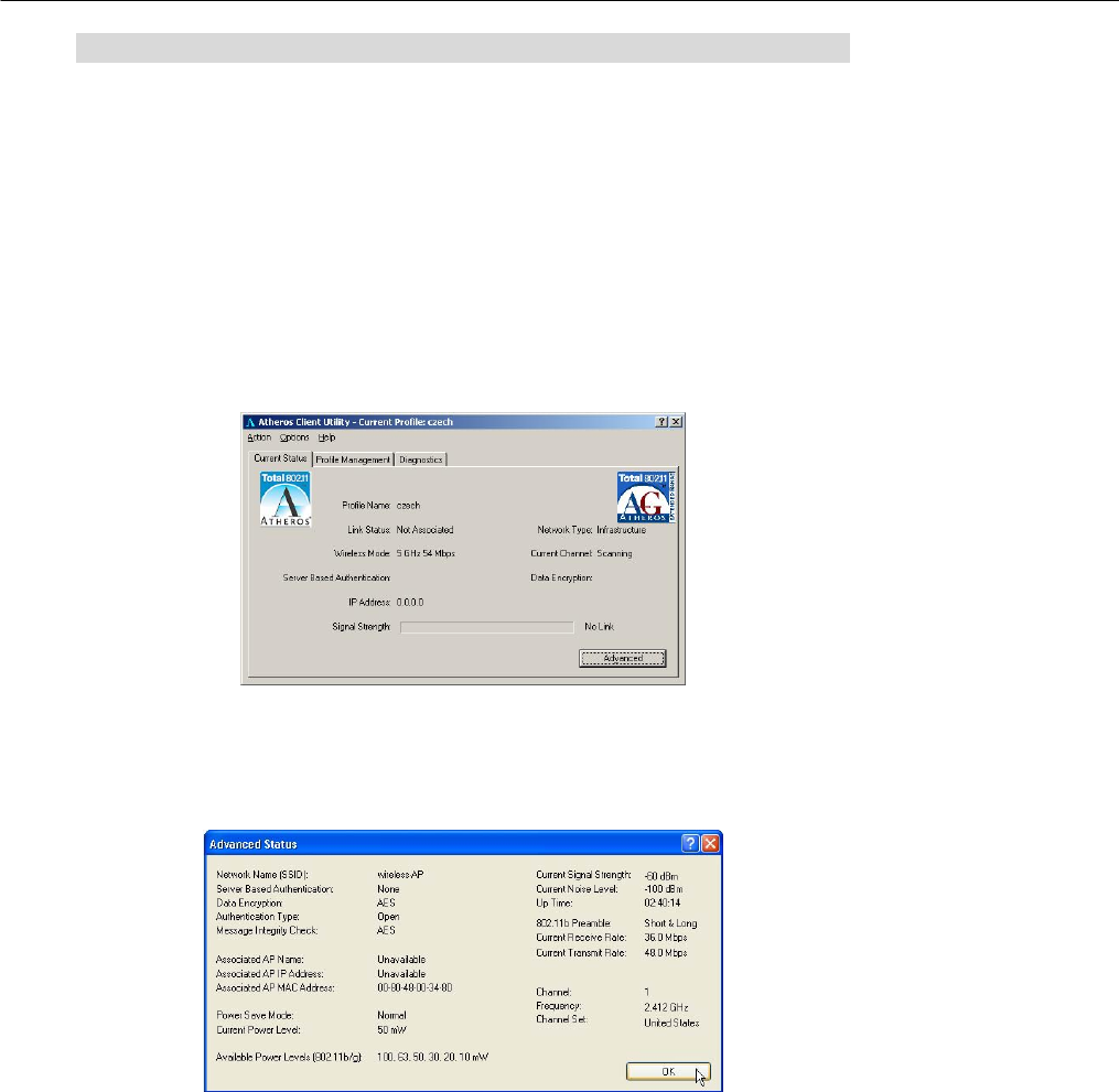
Wireless-AG Current Status
Upon clicking on the Advanced button, you will be able to view all
information on the respective profile, e.g. the types of encryption and
authentication, the signal strength, the MAC address of the connected
AP (if you are in Infrastructure mode), etc.
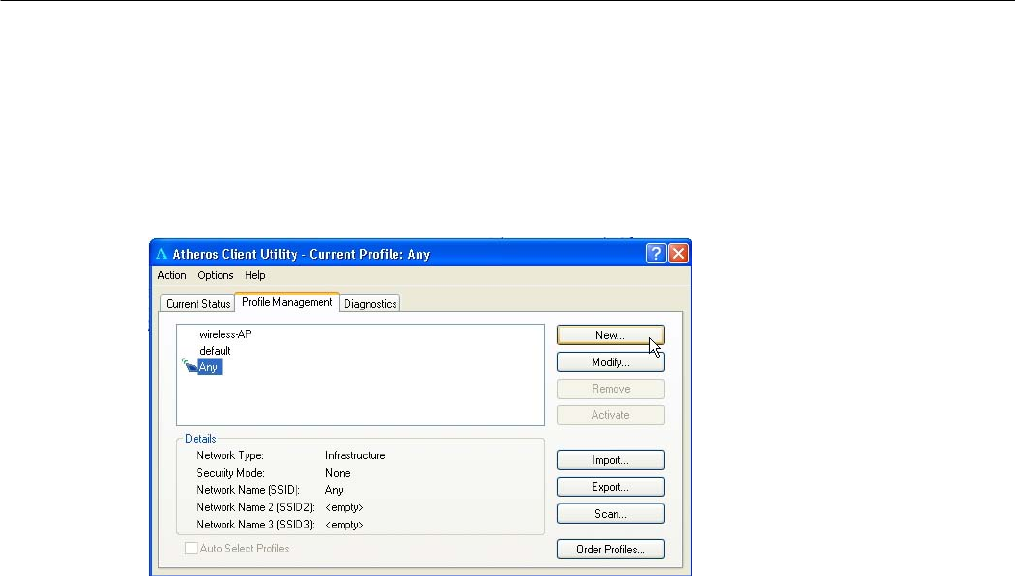
3.2 Profile Management Tab
Selecting this tab displays the profiles and the details.
You only need to create a profile if you have more than one wireless
connection.
3.3 Diagnostics Tab
The Diagnostics tab lists the following receive and transmit diagnostics for
packets received by or transmitted to the network adapter.
• Multicast packets transmitted and received
• Broadcast packets transmitted and received
• Unicast packets transmitted and received
• Total bytes transmitted and received
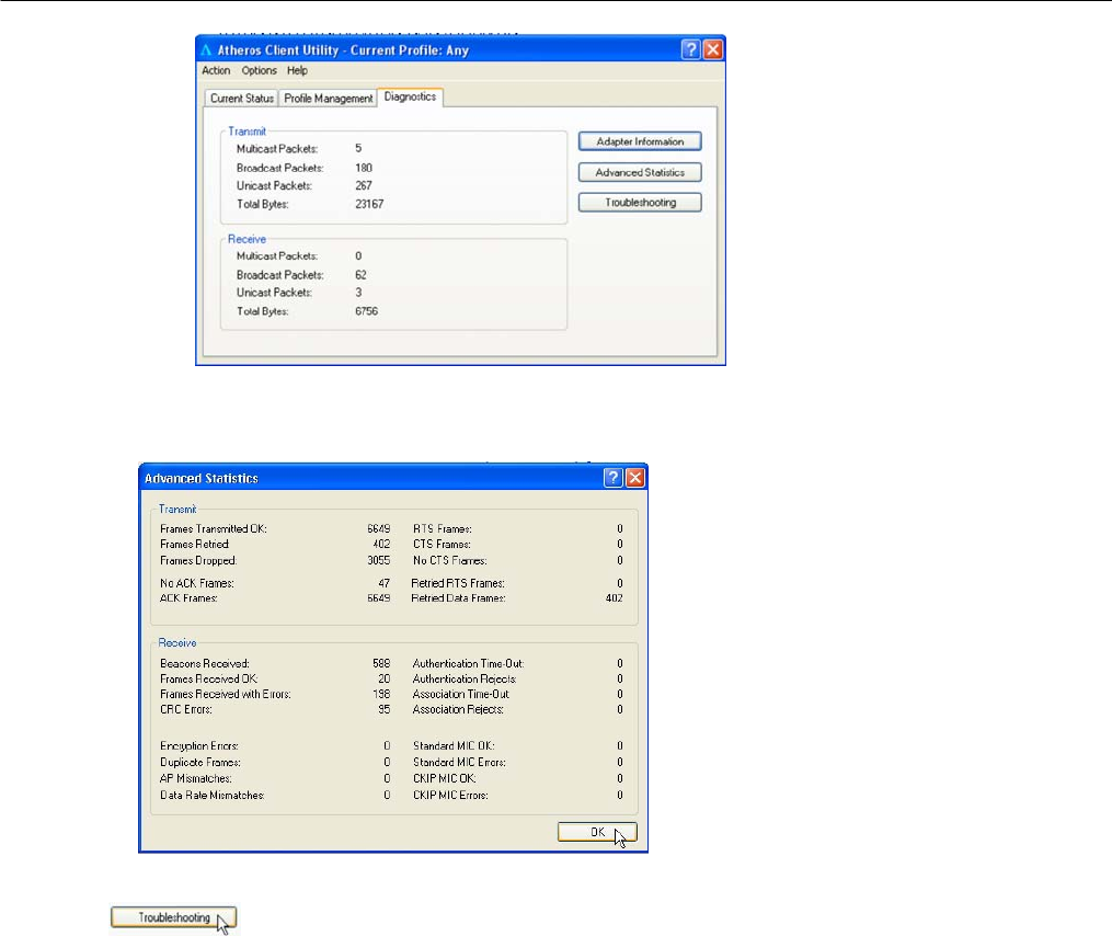
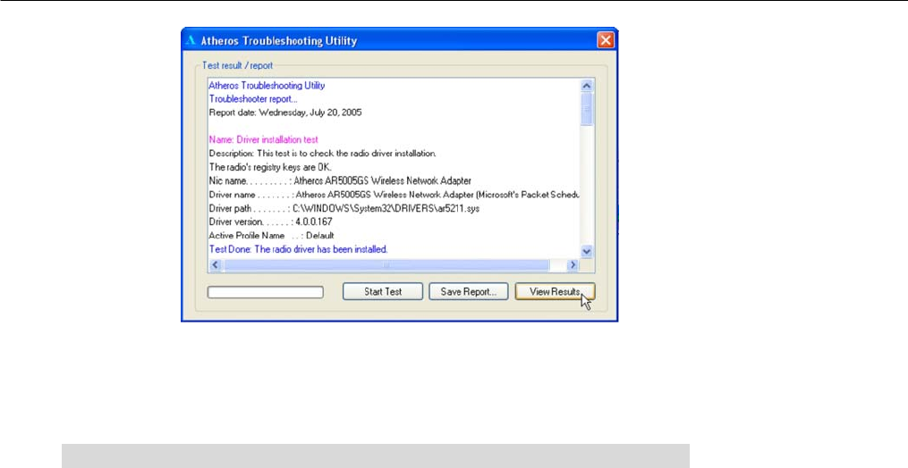
This button shows more detailed statistical information on frames that are
either received by or transmitted by the network adapter.
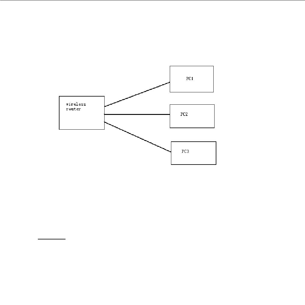
This button allows you to run the diagnostic test, save the test report and
view the test results on the wireless adapter configuration and association.
Chapter 4 Utility Configuration
This chapter will elaborate on the Client Manager configuration of the network
adapter using some simple examples.
the wireless clients communicate through router, which are devices that
act as base station for all wireless communication. Data packets from the
wireless clients are transferred to the wireless router before being
transmitted to other hosts on the network. The number of wireless clients
supported depends on the router.
4.1 Configuration Mode
In this example, three work station act as wireless clients to communicate
with the wireless router. Once all configuration has been done, wireless
clients with the same SSID as the AP will be able to access wirelessly to
PC1 via the wireless router
For Router
Ensure that you have enabled the DHCP server in your router and that
your wireless clients are set to receive their IP address dynamically so that
the wireless router can assign an IP address to them. Note the wireless
configuration settings of your router as shown in the figure above.
For PC 1
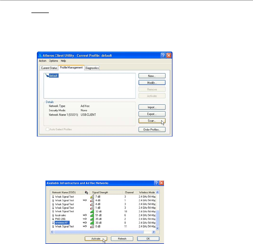
1. Activate your utility.
2. Go to the Profile Management tab, click on the Scan button to look
for the wireless AP.
3. Click on the Refresh button if your system is unable to detect your
wireless AP. Once found, select the Network Name (SSID) used by
the router: wireless-router and click on the Activate button to add it
to your profile list.
Notice that the SSID has already been pre-configured in this profile.
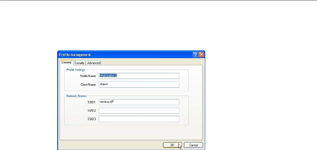
The SSID of both the wireless router and the wireless client must be the
same for them to communicate with one another.
4. Enter the Profile Name, e.g. Workstation 2 for easy identification.
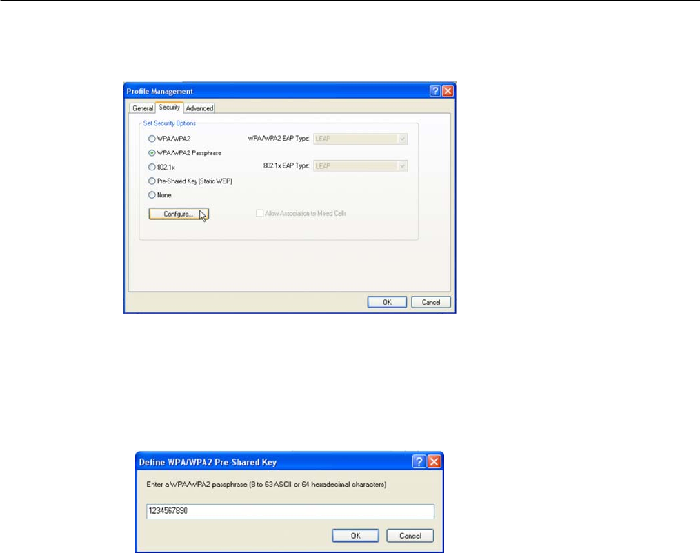
5. Next, proceed to the Security tab. The wireless client must use the
same security mode as the router. In our example, select WPA
Passphrase and click on the Configure… button.
6. Enter the encryption key in the field provided. Please note that this
key must be the same as the one that you had configured for your
wireless router.
7. Click on the OK button to update the changes.
Proceed to your Current Status tab to monitor the connection between
the router and the wireless client (PC2).
Alternatively, you can also check the connection from the MS-DOS
Prompt. From PC2, simply proceed to the Start Menu, Run… and type in
cmd. Click on the OK button.
In the MS-DOS Prompt window, type ping 192.168.168.1 –t, whereby this IP
address belongs to your access point.
When the screen appears:
Pinging 192.168.168.1: bytes=32 time=2ms TTL=128
Pinging 192.168.168.1: bytes=32 time=2ms TTL=128
Pinging 192.168.168.1: bytes=32 time=2ms TTL=128
…….
This indicates that the connection between the access point and the
wireless client has been established successfully!
4.2 Profile Management
This option allows you to manage your profile(s), set your security options,
and scan for other wireless networks.
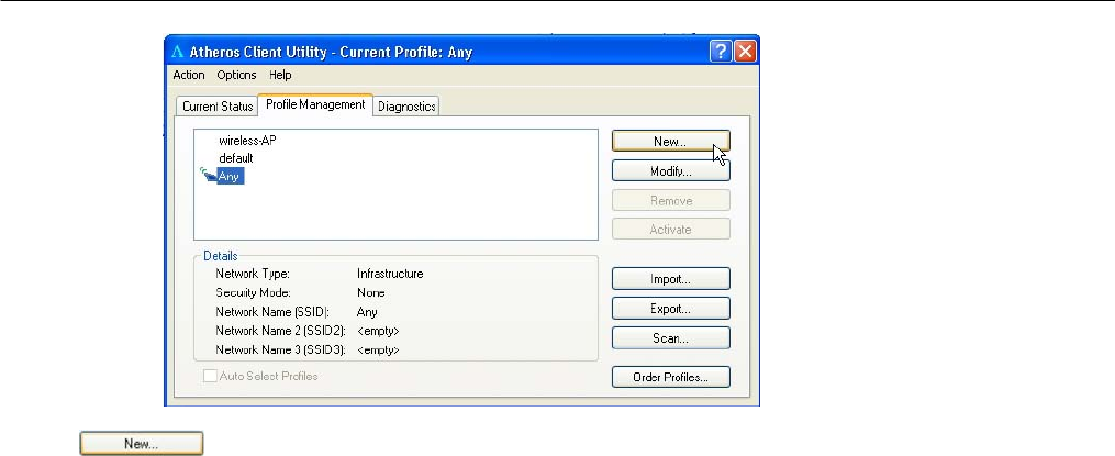
Click on New button to create a new profile. Enter the profile name (a
unique name to identify this profile), a client name and the SSID of the
wireless network to connect to. Note that the Client name refers to the
name that is registered to your PC. You can enter up to 3 different SSIDs in
order of preference, per profile. We are using ABC as the profile name
and APP as the SSID1
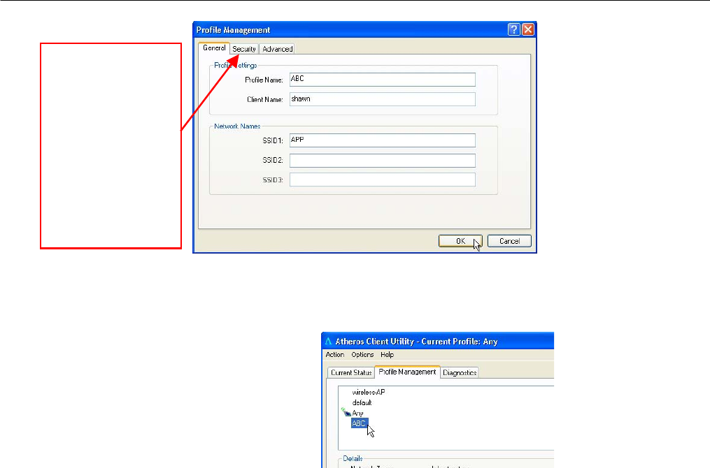
Click on the OK button to update the changes.
Notice that ABC has been added
to the profile list.
For details on ho
w
to set the different
authentication and
encryption types
available unde
r
the Security Tab,
kindly refer to
Chapter 7 “Types
of Authentication
and Encryption
mode”
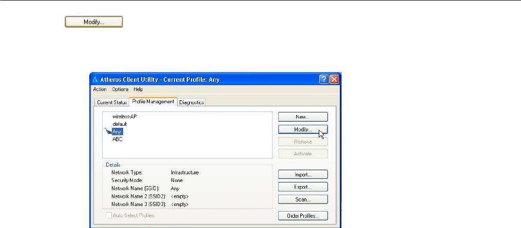
To modify an existing profile, select the profile that you wish to modify
and click on this button. We are using profile: Any as an example.
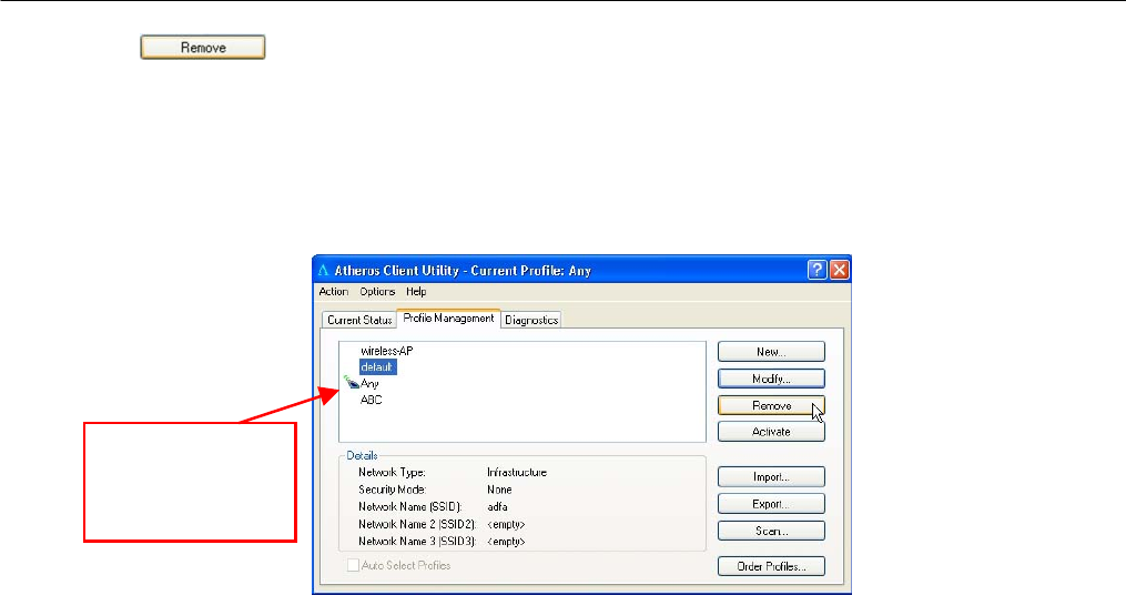
To delete an existing profile, select the particular profile that you wish to
delete and click on this button. We are using profile: default as an
example.
Note that the active profile (the profile that you are currently using)
cannot be deleted!
Active profile
indicated by this
icon cannot be
deleted!
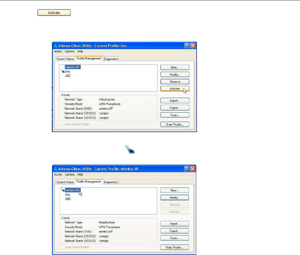
To activate a profile, select the profile and click on this button. We are
using profile: wireless-AP as an example.
Once a profile is activated, this icon will appear next to the profile
name: wireless-AP.
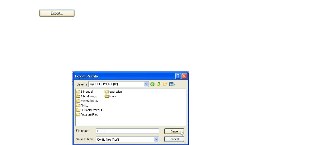
This function allows you to save the settings of your profile onto disk.
Select the profile that you wish to save and click on this button. We are
using profile: ESSID as an example.
Choose the folder to save to, enter the name under which to save the
profile and click on the Save button.
Now, your profile is saved to your selected folder.
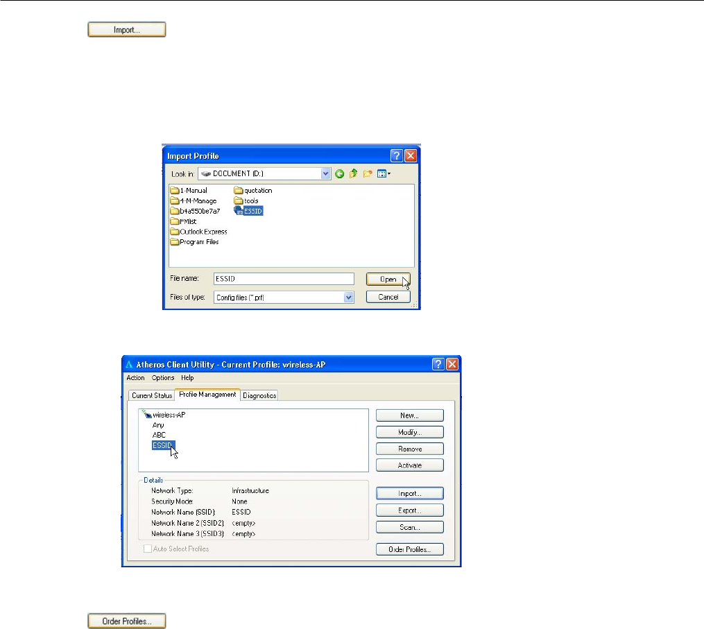
This function allows you to retrieve a saved profile from disk. We are using
profile: ESSID as an example.
Go to the folder where you have saved your profile, select ESSID.prf and
click on the Open button.
Notice that the profile: ESSID has been imported to the list of profiles.
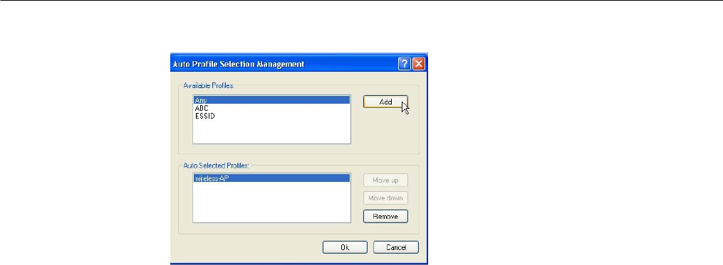
If you have created several profiles, this function allows you to establish
the priority order in which the network adapter should try to connect to a
WLAN. If the network adapter is unable to connect to a wireless network
through the 1st profile, it will then try to connect using the 2nd profile and
so on.
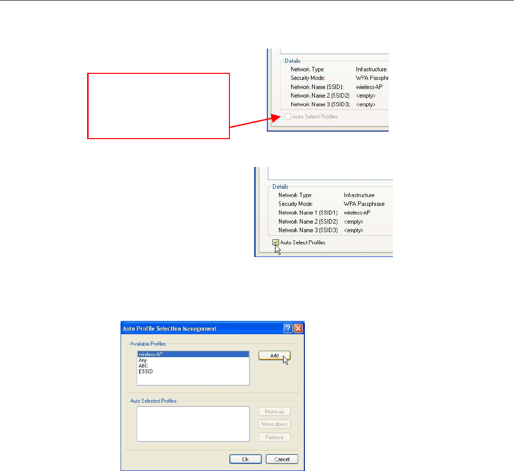
When auto profile selection is enabled,
the network adapter scans for available
wireless networks and will connect to the
highest priority profile that matches the
networks detected.
To do so, simply click on the Add button
from the Available Profiles list. Refer to
the screen shown below.
Please note that you need AT LEAST TWO profiles to activate the Auto
Select Profiles function; and that each of your profile must connect to at
least one Network Name (SSID).
Notice that when a selected profile has been added, it will be transferred
to the Auto Selected Profiles list.
Notice that if this function is
disabled, this means that
you have not added any
profile in the Auto Selected
Profiles list.
Select and click on the Add button to transfer another profile.
You need to transfer at least two profiles to the Auto Selected Profiles list
to activate the Auto Select Profile function.
Transmit Power Level
Specifies the wireless transmit power to be used. Reducing the power
level lowers the risk of interference with other nearby wireless devices and
conserves battery power but decreases radio range.
Power Save Mode (Only applicable to Infrastructure mode)
This feature reduces power consumption by the PCI adapter. There are 3
options for this mode:
• Off
The power management is disabled and the card consumes full
power from the computer.
• Normal
The driver turns off the power to the adapter for brief periods over
briefly spaced time intervals.
• Maximum
The driver turns off power to the adapter for longer periods over
more widely spaced time intervals.
The guideline for choosing between the Normal and Maximum
options:

The PCI adapter wakes up more often and responds sooner to
network requests in Normal mode than in Maximum mode; and the
Maximum mode consumes less power than Normal mode.
Network Type
Select either Infrastructure if you are connecting to the WLAN using an
access point
802.11b Preamble
The preamble is part of the IEEE 802.11b physical layer specification. It is
mandatory for all 802.11b devices to support the long preamble format,
but they may optionally support the short preamble. This PCI adapter
supports both the short and long preambles.
• Short & Long
This option allows communication with other 802.11b devices that
support short preamble to boost the throughput.
• Long Only
If your device is having trouble to communicate with other 802.11b
devices, you may try to select the Long Only option.
802.11 Authentication Mode (Only applicable to Infrastructure mode, after you
have enabled the encryption mode)
Select which mode the wireless adapter uses to authenticate to an
access point:
• Auto
Causes the PCI adapter to attempt authentication using shared
authentication. It then switches to open authentication if shared
authentication fails.
• Open
Enables the PCI adapter to attempt authentication regardless of its
WEP settings. It will only associate with the access point if its WEP
settings match those of the access point.
• Shared
Allows the adapter to authenticate and associate only if it has the
same WEP settings as the access point
Appendix
1.Technical Specifications
Network Protocol, Standards and Electrical Emissions
Industry Standards • IEEE 802.11g
• IEEE 802.11b
Performance
Operating Frequency • 2412~2462MHz
Modulation • Binary Phase Shift Keying (BPSK)
• Quadrature Phase Shift Keying (QPSK)
• Complementary Code Keying (CCK)
• 16 QAM
• 64 QAM
• DBPSK
• DQPSK
Antenna Type External 2dBi antenna and an SMA-type
connector
Network Interface PCI 2.3 compatible
Physical and Environment
Environmental Requirements
Operating temperature:
Storage temperature:
Operating humidity:
Non-operating humidity:
0°C to 50°C
-20°C to 70°C
10% to 70% RH
5% to 90% RH
Power Consumption 3.3V DC, 2A
Physical Dimension 60mm x 46 mm x 14 mm (LxWxD)