Compuprint POLLUX Printer User Manual Manual Part 1
Compuprint SpA Printer Manual Part 1
Contents
- 1. Manual Part 1
- 2. Manual Part 2
- 3. Manual Part 3
Manual Part 1
9
90
07
78
8
p
pl
lu
us
s
9
90
07
78
8D
D
p
pl
lu
us
s
U
Us
se
er
r
M
Ma
an
nu
ua
al
l
Rev. 001

Compuprint Information
Thanks for choosing the 9078/78D plus printer.
Your printer is a reliable working equipment that will be very useful in your daily job.
Our printers have been designed to be compact and respectful of the work environment. They offer
a wide range of features and multiple functions that confirm the high technological level reached
by the Compuprint S.p.A.
To maintain these printing performances unchanged in the long run, Compuprint has developed
specific consumable accessories for each printer type (for example: ribbon cartridges for dot matrix
printers, toner and OPC cartridges for laser printers, bubble ink jet cartridges for inkjet printers)
that assure an excellent operation with high printing quality level reliability.
Compuprint recommends to use only its original consumables with original packaging
(identified by its holographic label). In this way, a proper use of the printer at quality level
stated in the product characteristics can be assured. All typical usage problems related to not
certified consumables may be avoided, such as an overall quality print level degradation and,
often, the reduction of the product life due to the fact that the proper working conditions for the
print heads, OPC cartridge and other printer parts are not assured.
Moreover, Compuprint does not only certify its consumables in terms of working conditions but
also carefully controls their compliance with the international standard rules concerning:
• no cancerous materials;
• no flammability of the plastic materials;
• other standards
Compuprint advises the customers not to use products for which the compliance to this safety
rules are not warranted.
Finally seek your dealer or contact a Compuprint office and be sure that are provided you the
original Compuprint consumables.

CCoommpplliiaannccee SSttaatteemmeennttss
F
FC
CC
C
C
Co
om
mp
pl
li
ia
an
nc
ce
e
S
St
ta
at
te
em
me
en
nt
t
(
(U
US
SA
A)
)
This equipment complies with Part 15 of the FCC Rules. Operation is subject to the following
two conditions: (1) This device may not cause harmful interference, and (2) this device must
accept any interference received, including interference that may cause undesired operation. If
this equipment does cause harmful interference to radio or television reception, which can be
determined by turning the equipment off and on, the user is encouraged to try to correct the
interference by one or more of the following measures:
• Reorient or relocate the receiving antenna.
• Increase the separation between the equipment and receiver.
• Connect the equipment to an outlet on a circuit different from that to which the receiver in
connected.
• Consult the dealer or an experienced radio/TV technician for help.
FCC Warning
Changes or modifications not expressly approved by the party responsible for compliance could
void the user’s authority to operate the equipment.
N
No
ot
te
e
t
th
he
e
f
fo
ol
ll
lo
ow
wi
in
ng
g:
:
• The use of a non-shielded interface cable with the referenced device is prohibited.
• The length of the parallel interface cable must be 3 meters (10 feet) or less.
• The length of the serial interface cable must be 15 meters (50 feet) or less.
• The length of the power cord must be 3 meters (10 feet) or less.

Compliance Statement (Canada)
This digital apparatus is in conformity with standard NMB-003 of Canada.
Cet appareil numérique est conforme à la norme NMB-003 du Canada.
Übereinstimmungserklärung (Deutschland)
Bescheinigung des Herstellers/Importeurs:
Hiermit wird bescheinigt, dass der Drucker der Maschinenlärminformationsverordnung 3.
GSGV, 18.01.1991 entspricht: Der höchste Schalldruckpegel beträgt 70 dB (A) oder weniger
gemäß EN27779-1991.
Compliance Statement (Europe)
W
Wa
ar
rn
ni
in
ng
g
T
Th
hi
is
s
p
pr
ro
od
du
uc
ct
t
m
me
ee
et
ts
s
t
th
he
e
i
in
nt
te
er
rf
fe
er
re
en
nc
ce
e
r
re
eq
qu
ui
ir
re
em
me
en
nt
ts
s
o
of
f
E
EN
N5
55
50
02
22
2.
.
I
In
n
a
a
d
do
om
me
es
st
ti
ic
c
e
en
nv
vi
ir
ro
on
nm
me
en
nt
t,
,
t
th
hi
is
s
p
pr
ro
od
du
uc
ct
t
m
ma
ay
y
c
ca
au
us
se
e
r
ra
ad
di
io
o
i
in
nt
te
er
rf
fe
er
re
en
nc
ce
e
i
in
n
w
wh
hi
ic
ch
h
c
ca
as
se
e,
,
t
th
he
e
u
us
se
er
r
m
ma
ay
y
b
be
e
r
re
eq
qu
ui
ir
re
ed
d
t
to
o
t
ta
ak
ke
e
a
ad
de
eq
qu
ua
at
te
e
m
me
ea
as
su
ur
re
es
s.
.
Energy Star
As an ENERGY STAR® Partner, COMPUPRINT has determined that this product meets the
ENERGY STAR® guidelines for energy efficiency. The International ENERGY STAR® Office
Equipment Program is an international program that promotes energy saving through the use of
computers and other office equipment. The program backs the development and dissemination of
the products with functions that effectively reduce energy consumption. It is an open system in
which business proprietors can participate voluntarily. The targeted products are office
equipment such as computers, displays, printers, facsimiles and copiers. Their standards and
logos are uniform among participating nations.

International Compliance
EN55022:1998 Emissions Series
EN 61000-3-2:1995 Power line harmonics
EN 61000-3-3:1995 Power line flicker
EN55024:1998 Immunity Characteristics
EN61000-4-2:1995 E.S.D.
EN61000-4-3:1995 Radiated Susceptibility
EN61000-4-4:1995 E.F.T
EN61000-4-5:1995 Surge
EN61000-4-6:1996 R.F. Common mode
EN61000-4-11:1994 Voltage dips and interruptions
S
Sa
af
fe
et
ty
y
I
In
nf
fo
or
rm
ma
at
ti
io
on
n
A. Never remove any printer cover unless it is necessary for the installation of a printer accessory
and expressly described in this manual.
B. Please retain the printer covers in a safe place because they should be reinstalled if you
decide to remove any printer accessory.
The following areas of the printer should be covered for safety reasons:
Rear Tractor Area Cover
Tractor Fixing Area Covers
ASF Installation Area
Covers
The above openings must always be protected with their cover when the corresponding option is
not installed. Do not touch inside and do not insert any object into these openings or into the
gears.

T
Ta
ab
bl
le
e
o
of
f
C
Co
on
nt
te
en
nt
ts
s
Safety Information......................................................... iii
Table of Contents..........................................................iv
Getting to Know Your Printer ....................................... 1
Printer Features..............................................................................1
Unpacking Your Printer.................................................................2
Printer Parts....................................................................................3
Front View ...................................................................................3
Rear View.....................................................................................5
Setting Up Your Printer ................................................. 6
Choosing a Suitable Location........................................................6
Printer Assembly............................................................................7
Removal of the Shipment Locks................................................7
Ribbon Cartridge Installation....................................................8
Upper Push Tractor Installation (9078D plus model only)..13
Host Computer Connection .........................................................15
Software Driver Selection............................................................16
Power Connection.........................................................................17
Selecting the Display Language................................. 19
Configuring the Printer................................................ 20
Operator Panel Presentation.......................................................20
Display Messages......................................................................21
Indicators ...................................................................................25
Function Keys............................................................................26
Printer Setups...............................................................................31
Entering the Printer Setups ....................................................31
Moving within the Printer Setups...........................................31
Leaving the Printer Setups......................................................32
Power-On Configuration..............................................................33
Entering the Power-On Configuration ...................................33
Program Setup..............................................................................65
Entering the Program Setup....................................................65
How to Select the Paper Path......................................................89
How to Use the Tear-Off Function..............................................90
Selection of the Paper Size.......................................................90
Adjusting the Tear-Off Position...............................................91
Selection of the Tear-Off Mode................................................92
How to Lock/Unlock the Access to the Printer Setups.............93
How to Handle the Paper Parking..............................................94
Paper Handling............................................................. 99
Paper Paths...................................................................................99
Paper Specifications ...................................................................100
Fanfold Paper (9078 plus and 9078D plus models)............100
Envelopes (9078 plus model only).........................................100
Cut Sheets (9078 plus model only)........................................101
Cut Sheets ...................................................................................102
Cut Sheets Loading Modes....................................................102
Loading Cut Sheets.................................................................103
Fanfold Paper..............................................................................105
Loading Paper Using the Lower Tractor..............................105
Loading Paper Using the Upper Tractor..............................112
Loading Paper Using the Lower Push Tractor and the Rear
Pull Tractor (option)................................................................117
Printer Maintenance and Troubleshooting.............. 120
Cleaning the Printer...................................................................120
Replacing the Ribbon Cartridge................................................121
Printing the Self Test.................................................................122
Error Handling............................................................................123

1
G
Ge
et
tt
ti
in
ng
g
t
to
o
K
Kn
no
ow
w
Y
Yo
ou
ur
r
P
Pr
ri
in
nt
te
er
r
P
Pr
ri
in
nt
te
er
r
F
Fe
ea
at
tu
ur
re
es
s
• 24 Needle Print Head
• 136 columns
• Draft printing at 700 cps, LQ printing at 133 cps
• IBM Proprinter XL24E/XL24,Personal Printer 2391+ and EPSON LQ 1050-2550 emulations
• Multiple copies (1 original and 7 copies)
• Automatic paper path selection
• Easy operability via operator panel menu and S/W commands
• Optional Automatic Sheet Feeder (120 sheets capability) which handles cut sheets,
multicopies and envelopes, accepts up to two additional paper bins and includes paper stacker
• Optional color kit
• Optional cutter
• Usage of all specific features by means of the Specific Software Driver which is applicable to
the most popular S/W Packages
• Plug & Play capability for Windows 95/98/2000®
• Bi-directional IEEE 1284 parallel interface and standard serial RS-232/C and RS-422/A
interface for the standard printer. A dedicated model is available for the network connections
through an integrated Ethernet 10/100 Base-T interface, that coexists with the parallel
interface. Both models support the automatic switching between the available interfaces.
2
U
Un
np
pa
ac
ck
ki
in
ng
g
Y
Yo
ou
ur
r
P
Pr
ri
in
nt
te
er
r
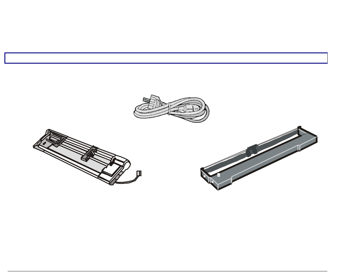
Together with the Installation Guide and the CD-ROM with the User Manual, the following items
are included in the box:
Notify any damage to your supplier.
Upper Push Tractor
(9078D plus model only) Ribbon Cartridge
Power Cable
3
P
Pr
ri
in
nt
te
er
r
P
Pa
ar
rt
ts
s
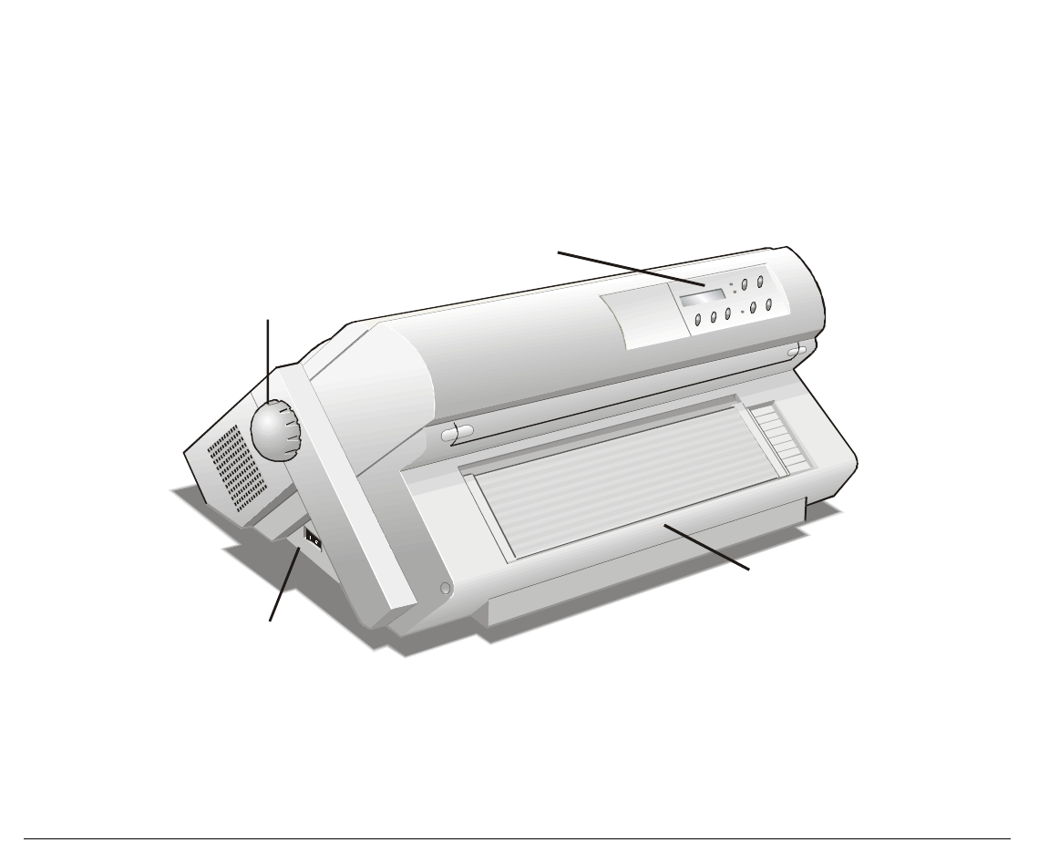
F
Fr
ro
on
nt
t
V
Vi
ie
ew
w
9078 plus model
Push Tractor Cover
Operator Panel
Paper Knob
Power Switch
Paper Guides
Cut Sheet Support
4
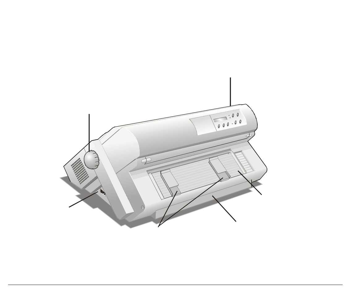
9078D plus model
Push Tractors Cover
Operator Panel
Paper Knob
Power Switch
5
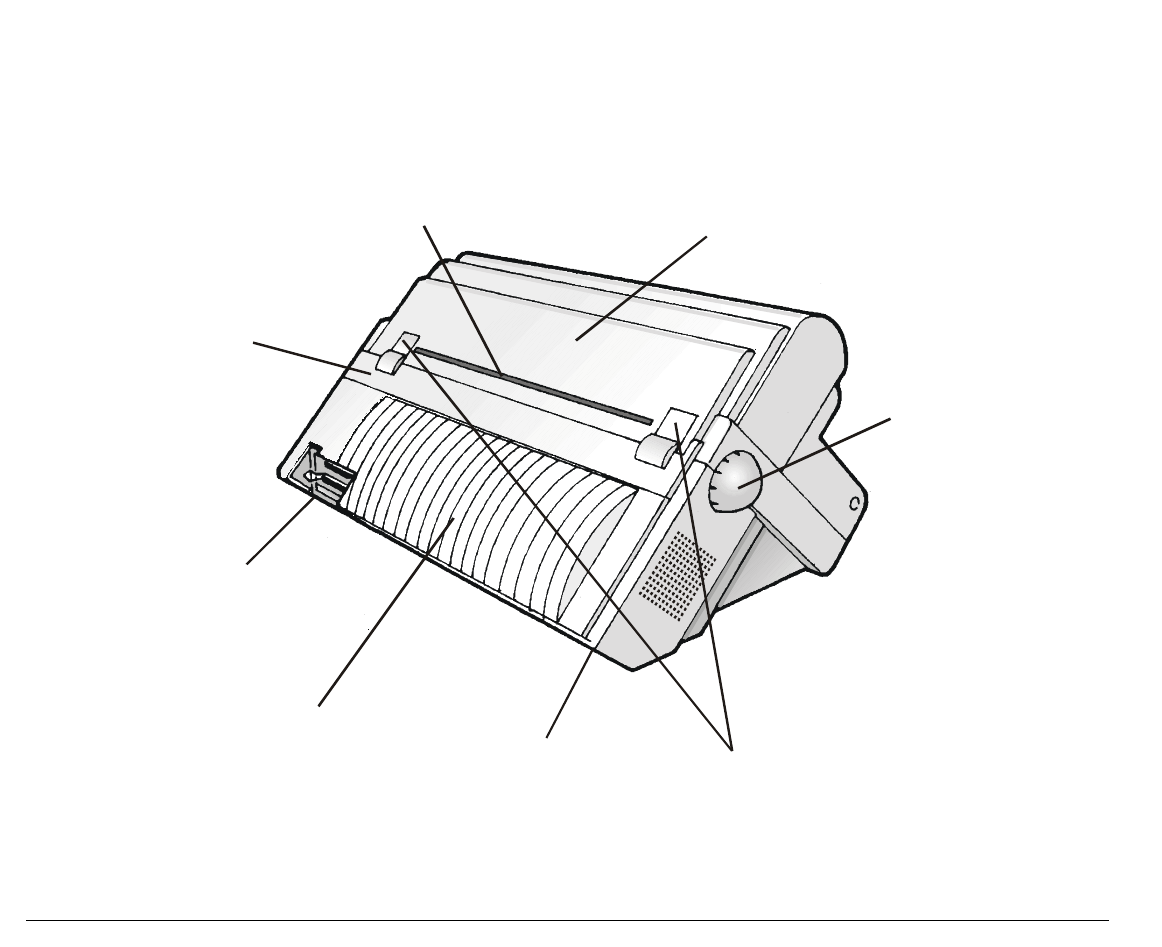
R
Re
ea
ar
r
V
Vi
ie
ew
w
ASF Area Cover
Power Cable Connector Rear Tractor Installation
Area Covers
Paper Knob
Top Cover
Rear Tractor Area
Cover
Interface Connectors
Rear Paper Slot
6
S
Se
et
tt
ti
in
ng
g
U
Up
p
Y
Yo
ou
ur
r
P
Pr
ri
in
nt
te
er
r
C
Ch
ho
oo
os
si
in
ng
g
a
a
S
Su
ui
it
ta
ab
bl
le
e
L
Lo
oc
ca
at
ti
io
on
n
Consider the following points when you
choose the location for your printer:
• The distance between the printer and
the host computer must not exceed
the length of the interface cable;
• The location must be sturdy,
horizontal and stable;
• Your printer must not be exposed to
direct sunlight, extreme heat, cold,
dust or humidity (see "Printer
Specifications" later);
• You need an AC power outlet
compatible with the plug of the
printer's power cord. The voltage of
the outlet must match the voltage
shown on the printer's Rating Plate;
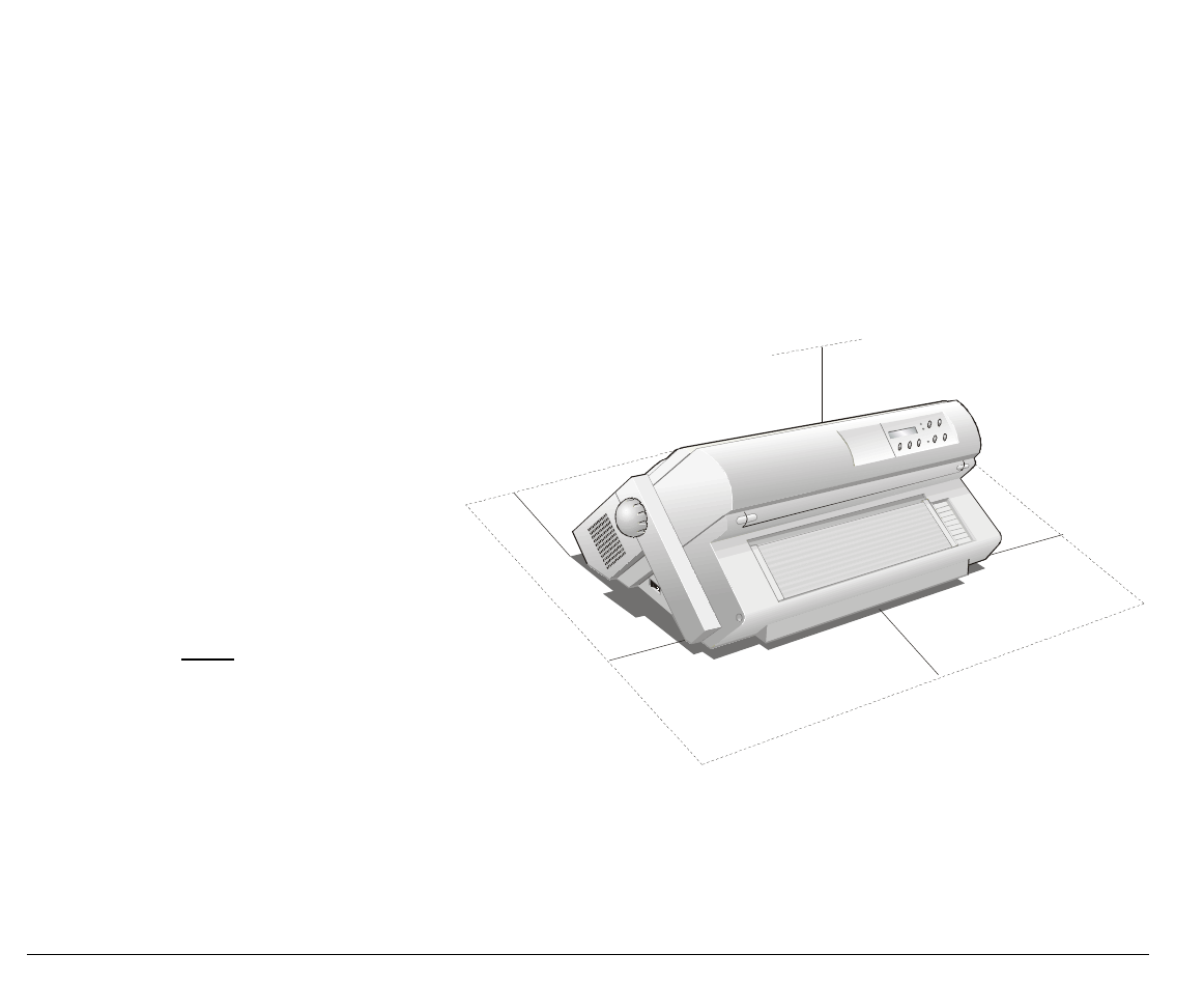
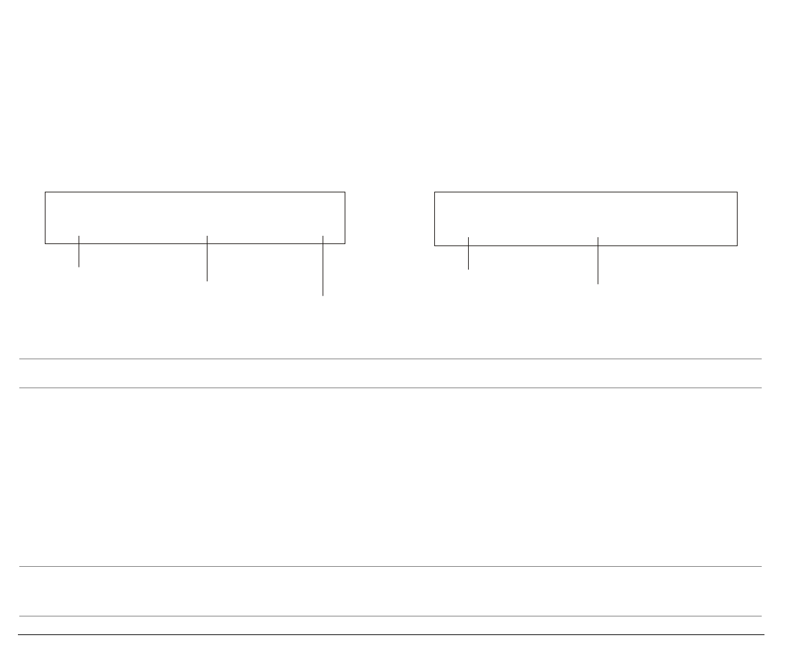
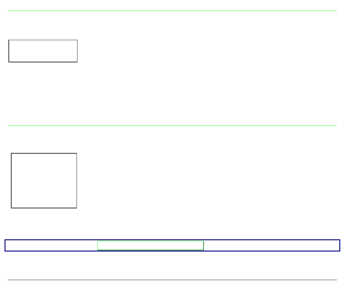
Additionally, you must make sure that
when you install the printer in the
selected location, there are sufficient
clearances on all sides for easy operation.
The required space is shown in the
figure:
80 cm
31.5 in.
20 cm
7.9 in
100 cm
39.4 in
20 cm
7.9 in
100 cm
39.4 in
7
P
Pr
ri
in
nt
te
er
r
A
As
ss
se
em
mb
bl
ly
y
R
Re
em
mo
ov
va
al
l
o
of
f
t
th
he
e
S
Sh
hi
ip
pm
me
en
nt
t
L
Lo
oc
ck
ks
s
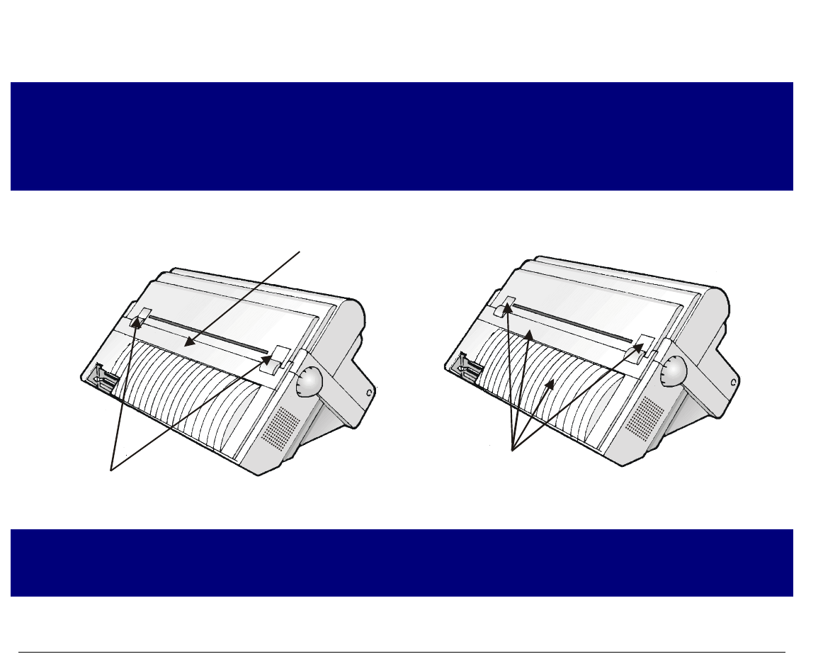
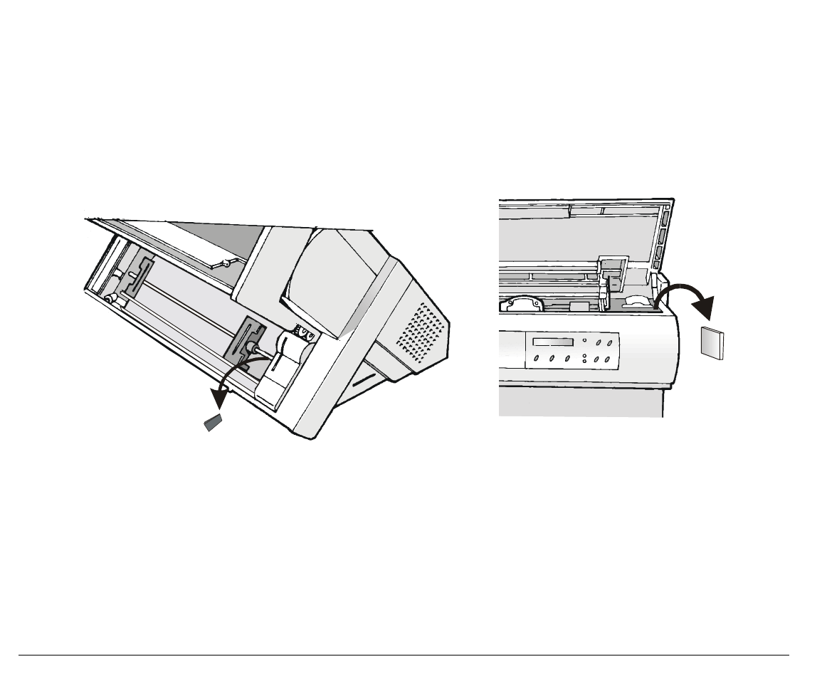
Open all the printer covers and make sure that you remove all the shipment locks from the
printer.
8
R
Ri
ib
bb
bo
on
n
C
Ca
ar
rt
tr
ri
id
dg
ge
e
I
In
ns
st
ta
al
ll
la
at
ti
io
on
n
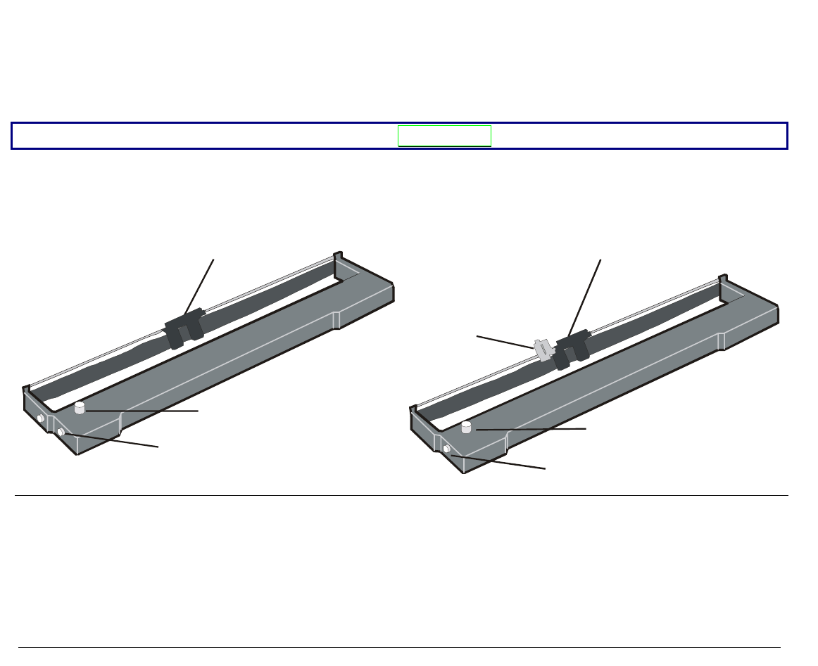
Two types of black ribbon cartridges are available for this printer, depending on whether the
color kit is installed or not.
Make sure that you are using only Compuprint original consumables.
1. Make sure that the printer is turned off.
2. Find the ribbon cartridge among the accessories.
Ribbon guide
Tension Knob
Cartridge Pin
Ribbon guide
Color Kit Guide
Tension Knob
Cartridge Pin
to be used, when the color kit option is not
installed to be used, when the color kit option is
installed
9
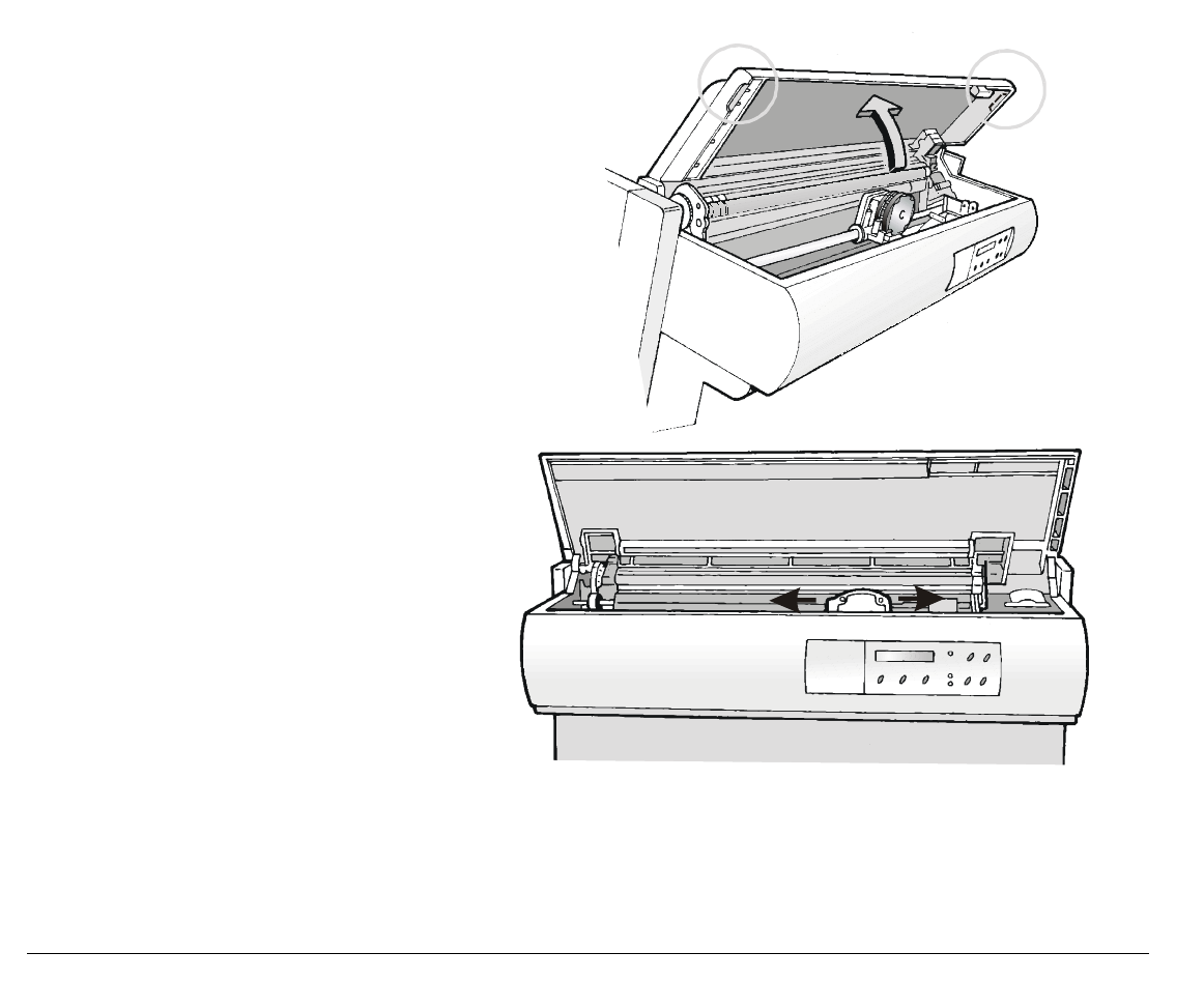
3. Open the top cover using the
small handles on either side of the
top cover.
4. Turn the printer on. The print
carriage prepares for ribbon
cartridge installation.
10
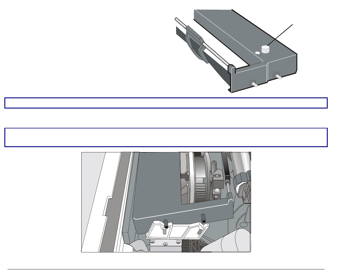
5. Before installing the ribbon cartridge turn
the ribbon winding knob in the arrow
direction (located on the cartridge) to take up
slack in the ribbon.
Ribbon Tension
Knob
To avoid damage to the ribbon, do not turn the winding knob in the wrong direction.
6. Align the cartridge pins with the locking grooves on the left and right cartridge supports.
The cartridge (black “Long Life” or color) to be used when the color kit is installed has only one
groove.
11
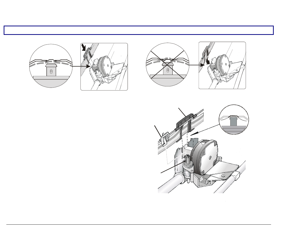
7. Slide and insert the ribbon guide between the print head and the ribbon guide mask holding it
perpendicular to the print head.
Make sure that the ribbon is inserted correctly between the print head and the print head mask.
OK NO
If the color kit option is installed on your
printer insert the white plastic holder
onto the color kit as shown in the
following figure.
Ribbon Guide
Holder for Color Kit
Color Kit

12
8. Turn the ribbon winding knob in the
arrow direction (located on the
cartridge) to take up slack in the
ribbon.
Ribbon Tension
Knob
9. Push the cartridge down gently until it clips into place at all four locking points.
10. Turn the ribbon winding knob again in the direction of the arrow to take up slack in the
ribbon.
11. To ensure that the ribbon guide runs freely along the ribbon, manually move the print
carriage horizontally.
If you need to replace the used ribbon cartridge, see "Replacing The Ribbon Cartridge", later in
this manual.
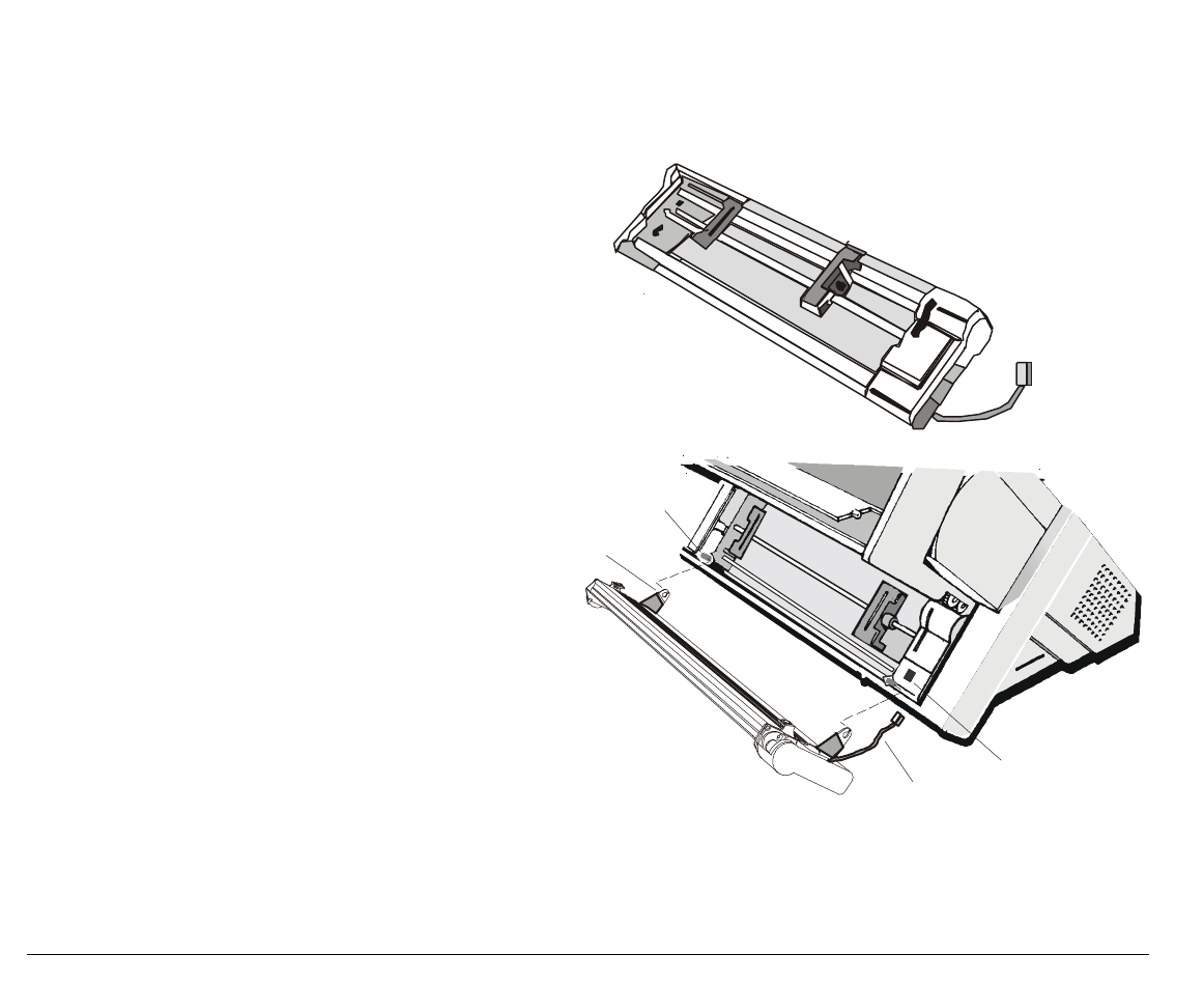
13
U
Up
pp
pe
er
r
P
Pu
us
sh
h
T
Tr
ra
ac
ct
to
or
r
I
In
ns
st
ta
al
ll
la
at
ti
io
on
n
(
(9
90
07
78
8D
D
p
pl
lu
us
s
m
mo
od
de
el
l
o
on
nl
ly
y)
)
An additional push tractor is provided with the 9078D plus printer. This second push tractor
unit can be installed in front position (on the lower push tractor).
1. Find the upper push tractor among
the accessories.
2. Install the upper push tractor
aligning both its hooks with the
lower push tractor pins and
inserting them into the
corresponding pins. Push the upper
tractor until it is fully engaged.
Insert the connector cable in the
electrical connector located in the
lower push tractor.
Upper Tractor Hook
Electrical Connector
Connector Cable
Lower Tractor Pin
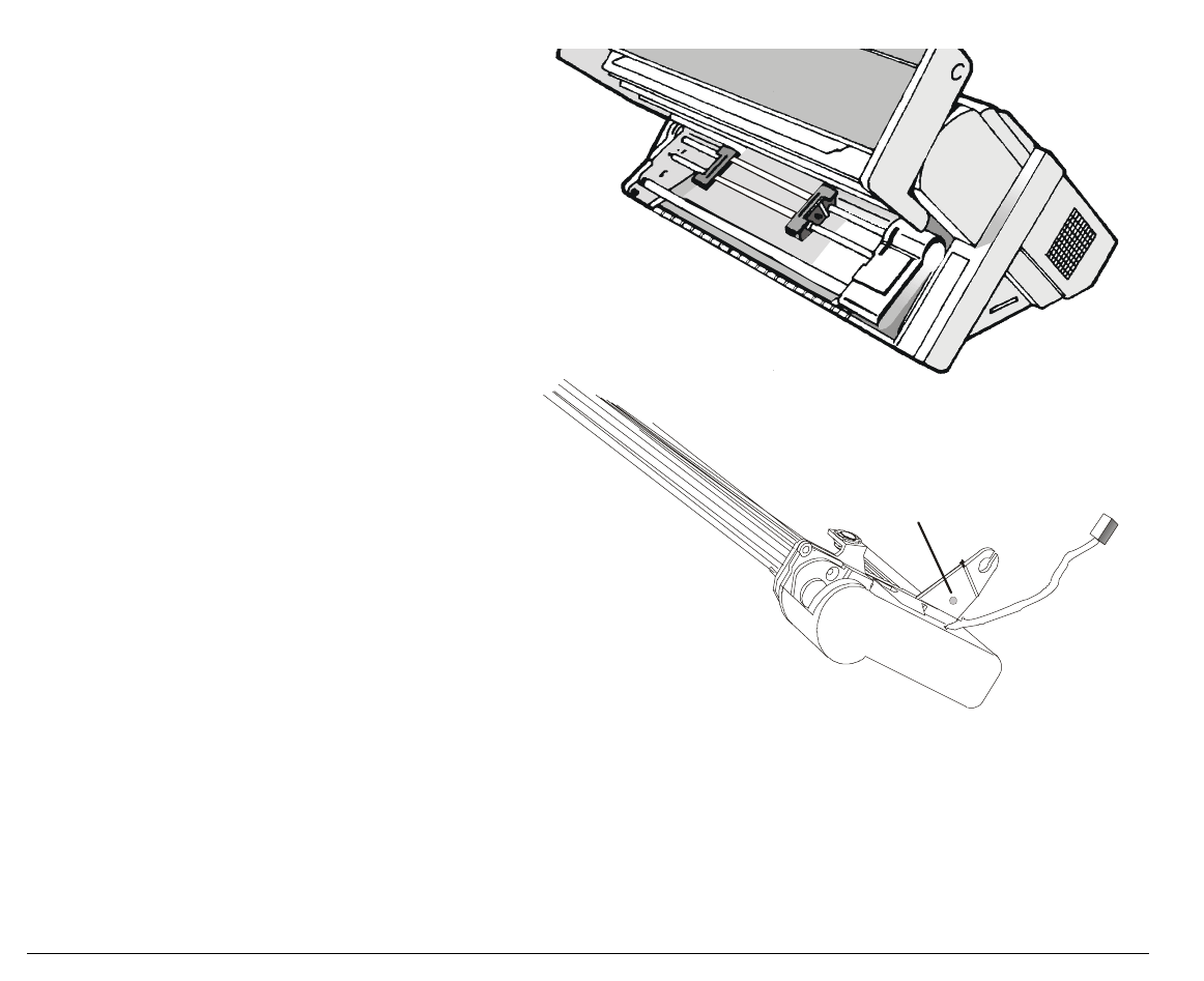
14
3. The upper push tractor must be
installed as shown in figure.
4. If you need to remove the upper push
tractor, turn the printer off. Take the
connector cable off and press on the
push buttons (located in the upper
push tractor hooks) to disengage the
tractor.
Push Button
15
H
Ho
os
st
t
C
Co
om
mp
pu
ut
te
er
r
C
Co
on
nn
ne
ec
ct
ti
io
on
n
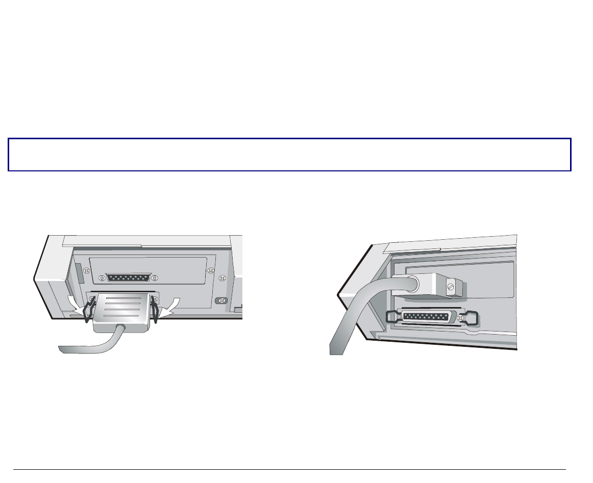
This printer can be connected to your host computer via two available interfaces. The interface
connectors are located on the rear of the printer.
• A bidirectional IEEE1284 parallel interface
• A RS-232/C or RS-422/A serial interface
Before connecting the interface cable, make sure that the printer and the host computer are
turned OFF .
Insert the parallel interface cable into the parallel connector and fasten it by means of the clips.
Insert the serial interface cable into the serial connector, and fasten it by means of the two
screws (use the screwdriver).
Parallel interface Serial interface

16
S
So
of
ft
tw
wa
ar
re
e
D
Dr
ri
iv
ve
er
r
S
Se
el
le
ec
ct
ti
io
on
n
At this point it is necessary to configure your printer for your application package. The
installation procedures depend upon the host environment.
Follow the instructions in the readme file you find on the CD-ROM.
In a WINDOWS 95/98/2000® environment the printer supports the Plug & Play feature.
The printer drivers of all Compuprint printers can be found at the Internet Address
http://www.compuprint.net/driver
17
P
Po
ow
we
er
r
C
Co
on
nn
ne
ec
ct
ti
io
on
n
Make sure that the power outlet matches the power rating of the printer. See the name plate of the
printer, that you find under the rear ASF cover.
In case the power rating does not correspond DO NOT CONNECT THE PRINTER TO THE MAINS.
Consult your dealer for help.
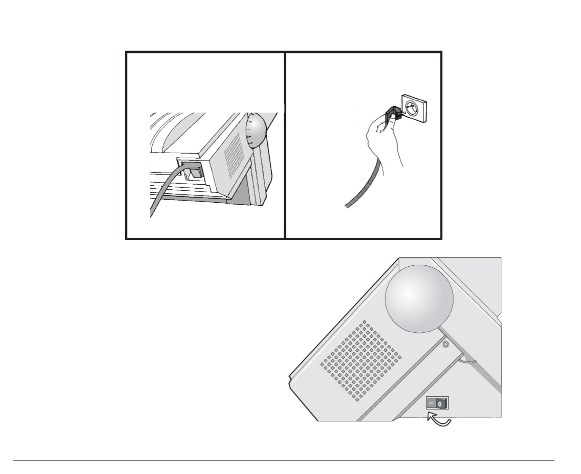
1. Make sure the power outlet is near the printer location and easily accessible.
Always use a grounded outlet.
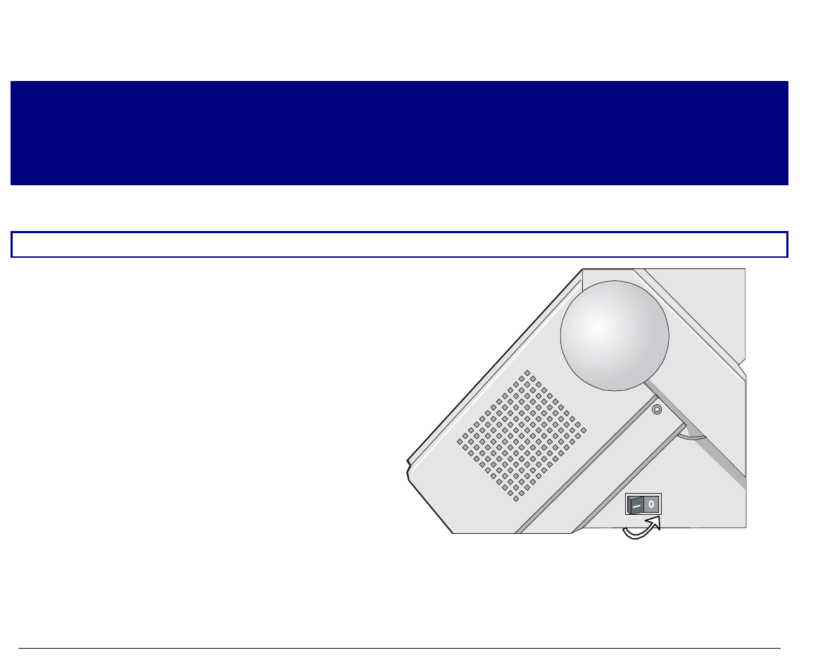
2. Make sure that the power switch is in 0
position (OFF).
18
3. Insert the power cable plug into the printer connector and the other power cable end into a
convenient outlet (the figure shows the European version).
12
4. If you need to turn the printer on, press the
power switch in the I position (ON).
19
S
Se
el
le
ec
ct
ti
in
ng
g
t
th
he
e
D
Di
is
sp
pl
la
ay
y
L
La
an
ng
gu
ua
ag
ge
e
The display messages for this printer can be displayed in five different languages: English (Default),
French, German, Italian and Spanish. To select the language, that you prefer, proceed as follows:
1. Press the
PROGRAM key and keep it pressed while powering on the printer until the following
message will be displayed:
RELEASE KEY
2. When you release the PROGRAM key, the following messages will be displayed:
9078 plus or 9078D plus
then,
PRINT OUT? NO
3. Press the ↓ key to enter the setup. The first setup item is displayed:
LOW. JAM SENS. Y
4. Press the ↓ key until the language first level function is displayed:
FUNCTIONS
5. Press the → key to pass to the second level functions:
PAPER OVERLY? NO for the 9078 plus model
or
SEQUENCE NONE for the 9078D plus model
6. Press the ↓ key until the setup language is displayed:
MENU ENGLISH
7. Press the → key to scroll the setup languages. When the desired language is displayed, press the
PROGRAM key to select it. The printer exits the setup. From now on the display messages appear
in the selected language.
20
C
Co
on
nf
fi
ig
gu
ur
ri
in
ng
g
t
th
he
e
P
Pr
ri
in
nt
te
er
r
O
Op
pe
er
ra
at
to
or
r
P
Pa
an
ne
el
l
P
Pr
re
es
se
en
nt
ta
at
ti
io
on
n
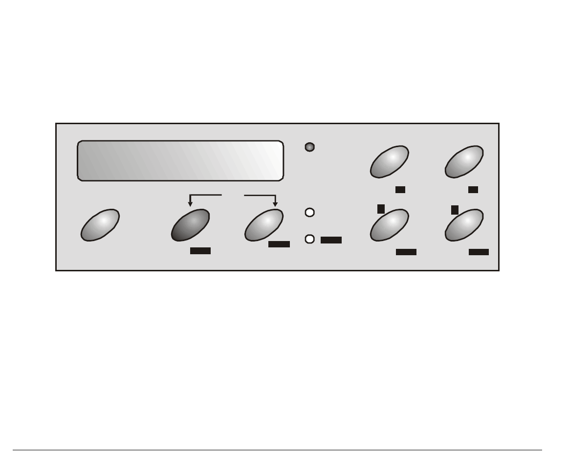
The operator panel enables you to perform many of the printer functions including paper path
selections, font selection and the printer setup.
ON LINE
PROGRAM
MACRO FONT
LFLOAD/FF
PROGRAM
READY
SHIFT SHIFT
PATH PARK
↓
↑
MICRO FEED
PITCH
QUIET
↑
↑
The operator panel consists of:
• A 16 character display (Liquid Crystal Display)
• Three function mode indicators
• Seven function keys
21
D
Di
is
sp
pl
la
ay
y
M
Me
es
ss
sa
ag
ge
es
s
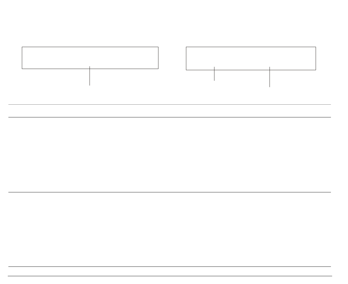
The printer display is used to indicate the printer status or to request an user intervention and
gives the following information:
• when paper is already loaded and the
printer is off line (READY indicator unlit):
• when paper is already loaded and the
printer is on line (READY indicator lit):
M1 - Lower Push E
Current Macro Current Paper Path
Current Emulation
M1 - Lower Push
Current Macro Current Paper Path
where:
M1, M2, M3, M4 Indicate which of the four User Macros is currently used.
ASF1
ASF2
ASF3
LOWER PUSH
UPPER PUSH
PUSH-PULL
LOW.PUSH&MF
PSH-PLL&MF
MANUAL FORM
Indicates which Paper Path is currently used. The printer displays only the
messages related to the installed devices.
LOW.PUSH&MF: The lower push paper path and manual single sheet path
are selected (9078 plus model only).
PSH-PLL&MF: The push-pull paper path and manual single sheet path are
selected (9078 plus model only).
MANUAL FORM: The manual single sheet path is selected (9078 plus model
only).
E, I This acronym indicates the Emulation currently used. E indicates the
EPSON emulation, whereas I indicates the IBM emulation.
22
• when there is no paper loaded and the
printer is off line (READY indicator unlit):
• when there is no paper loaded and the
printer is on line (READY indicator lit):
Load Lower Push
Current Paper Path
M1 - Lower Push
Current Macro Current Paper Path
where:
M1, M2, M3, M4 Indicate which of the four User Macros is currently used.
LOAD ASF1
LOAD ASF2
LOAD ASF3
LOAD LOWER PUSH
LOAD UPPER PUSH
LOAD LOW.PUSH&MF
LOAD MANUAL FORM
LOAD PSH-PLL&MF
LOAD PUSH-PULL
Indicates that the currently selected paper path is out of paper.
The messages are displayed only for the available paper paths, according
to the installed devices.
ASF1
ASF2
ASF3
LOWER PUSH
UPPER PUSH
PUSH-PULL
LOW.PUSH&MF
PSH-PLL&MF
MANUAL FORM
Indicates which Paper Path is currently used. The printer displays only
the messages related to the installed devices.
LOW.PUSH&MF: The lower push paper path and manual single sheet
path are selected (9078 plus model only).
PSH-PLL&MF: The push-pull paper path and manual single sheet path
are selected (9078 plus model only).
MANUAL FORM: The manual single sheet path is selected (9078 plus
model only).

23
The following messages appear to indicate other printer conditions or user intervention requests.
The list is in alphabetical order:
Message Description
COVER OPEN
CLOSE COVER When the printer cover is not closed correctly, the buzzer sounds and the
display shows alternately these two messages.
EJECTING The printer is ejecting the paper out of the printer.
LOAD ASF1
LOAD ASF2
LOAD ASF3
LOAD LOWER PUSH
LOAD LOW.PUSH&MF
LOAD MANUAL FORM
LOAD PSH-PLL&MF
LOAD PUSH-PULL
LOAD UPPER PUSH
These messages are displayed when the corresponding paper path is out of
paper.
The printer displays only the messages related to the installed
devices.
LOW.PUSH&MF = Lower push and manual paper path.
PSH-PLL&MF = Push-Pull and manual paper path.
LOCKED MENU When the access to the Printer Setups has been locked at the power on,
the printer displays this message.
MACRO CHANGING The macro has been changed and the printer is updating the settings.
MICRO FEED DOWN ↓ The paper is fed in microsteps downwards when pressing the arrow key.
MICRO FEED UP ↑ The paper is fed in microsteps upwards when pressing the arrow key.
OPER. INTERRUPTED This message is displayed if the SHIFT key has been pressed to interrupt a
park procedure.
PARKING The printer is parking the fanfold paper.
PATH CHANGING The path has been changed and the printer is updating the settings.
PRESS A KEY
NVM CHANGED The NVM has been changed. Press any key to set the printer.
QUIET PRINT OFF Printing at normal noise level.
QUIET PRINT ON Printing at reduced noise level

24
Message Description
RELEASE KEY This message is displayed when you can release the PROGRAM key in the
Self-test selection or in the Power-on Configuration procedure.
RESET & BREAK When the input buffer is cleared an a break (250 msec.) on a serial
interface is sent pressing the PROGRAM and then the ON LINE keys.
SELF TEST The printer is printing the self-test page.
SHIFT FUNCTION This message appears to indicate that the Shift functions of the operator
panel keys have been selected pressing the SHIFT key.
TEAR IF NECESS.
PARK PAPER These messages are displayed when the printer receives a paper parking
command. Tear off the fanfold then press the PARK key to park the paper.
TEAR IF NECESS.
EJECT PAPER These messages are displayed when the printer receives a paper parking
command and the TEAR NO is selected for the tear-off function. Tear off
the fanfold then press the PARK key to park the paper.
TEAR OFF PAPER
PARK PAPER These messages are displayed when the printer receives a paper parking
command but was not able to execute it, because the paper to be parked is
longer than 18 inch. Tear off the fanfold paper and then press the PARK
key to park the paper.
TEAR OFF PAPER
EJECT PAPER These messages are displayed when the printer receives a paper ejecting
command (TEAR NO has been selected for the tear-off function) but was
not able to execute it, because the paper to be ejected is longer than 18
inch. Tear off the fanfold paper and then press the PARK key to eject the
paper.
UNLOCKED MENU When the access to the Printer Setups has been unlocked at the power on,
the printer displays this message.
For the error messages see "Error Handling" later in this manual.

25
I
In
nd
di
ic
ca
at
to
or
rs
s
Lit when the printer can receive and print data (printer online).
Blinks when there is data in the buffer and the printer is offline.
READY
Unlit, when the printer is disabled and the buffer does not contain any
data, or during the initialization, setup or tests.
PROGRAM
Blinks when one of the printer setup procedures has been selected:
Program Configuration or Power-On Configuration.
SHIFT
Lit when the alternate function of the keys has been enabled pressing the
SHIFT key.

26
F
Fu
un
nc
ct
ti
io
on
n
K
Ke
ey
ys
s
The function keys are enabled, when the printer is offline (READY indicator unlit). The function keys
have three functions each.
Normal Function The normal function of the keys does not require previous action to select it.
This function is indicated in black characters beside the function keys.
Shift Function The alternate function is selected pressing the SHIFT key.
The alternate functions of the keys are described on the gray areas beside the
keys. The SHIFT indicator is lit and the display shows SHIFT FUNCTION.
This function is not enabled, if the printer is in setup mode.
Program Function The program function is selected pressing the PROGRAM key, where:
• If you press the key while powering on the printer, the Power-On
Configuration is selected.
• Pressing the key when the printer is enabled without printing or disabled
(READY indicator unlit), the Program Setup is selected.
In the Program Setup mode only the four arrow keys and the PROGRAM key are
enabled.
When the printer is in setup mode, the PROGRAM indicator blinks.

27
ON LINE Key
ON LINE Enables or disables the printer.
Normal
Function • If this key is pressed while powering the printer on, the self test is
printed; the printout is stopped pressing this key again.
• In an error condition, once the error cause has been removed, press
this key to enable the printer.
• If the Tear-Off Function in the Program Setup is set to Manual,
press this key to position the paper for the Tear-Off.
Program
Function Pressing this key, the input buffer is cleared an a break (250 msec.) on
a serial interface is sent. The message RESET & BREAK is displayed.
PROGRAM Key
PROGRAM Enables the printer setups as follows:
Normal
Function • Pressing this key while powering on the printer, the Power-On
Configuration is selected.
• Pressing this key when the printer is enabled without printing or
disabled (READY indicator unlit), the Program Setup is enabled.
PITCH Shift
Function Selects the pitch to be used with the currently selected font. The
selected pitch is valid until the printer is turned off.
Program
Function Exits the current printer setup. See also “Leaving the Printer Setups”,
later in this section.

28
SHIFT Key
SHIFT Enables the alternative key functions.
Normal
Function If the printer is receiving print data, press the ON LINE key before
pressing the SHIFT key.
If no printing data are in the print buffer, pressing the SHIFT key, the
printer goes offline.
The display then shows SHIFT FUNCTION to indicate that the Shift
Function of the keys is enabled.
May be used to abort paper parking procedure. See also “How to Handle
the Paper Parking”, later in this manual.
Shift Function Disables the alternative key functions.
If pressed after the PARK key, the parking procedure is interrupted.
LOAD/FF Key
LOAD/FF Normal
Function Executes a Form Feed (FF): when paper is loaded into the printer, it
advances to the following page; if no paper is loaded, it is positioned for
printing.
↑ Shift Function Moves the paper forward in microsteps. Keeping the key pressed the
paper is moved continuously at increasing speed.
↑ Program
Function Scrolls the parameters of the functions or macros backwards.

29
LF Key
LF Normal
Function Performs a line feed according to the current line spacing settings.
↓ Shift Function Moves the paper backward in microsteps. Keeping the key pressed the
paper is moved continuously at increasing speed.
↓ Program
Function Scrolls the setup and macro functions forward.
MACRO Key
MACRO Normal
Function Selects one of the user macros (Macro 1, Macro 2, Macro 3 or Macro 4). If
you want to select the displayed macro, wait for 2 seconds without
pressing any key and the parameters of this macro will be set .
PATH Shift Function Selects one of the paper paths. The parameters of the displayed path are
set pressing the SHIFT key or waiting for 2 seconds without pressing any
key.
← Program
Function Scrolls the setup and macro functions backward.
FONT Key
FONT Normal
Function Selects the font to be used with the currently selected pitch. The selected
font is valid until the printer is turned off.
PARK Shift Function Parks the paper in the currently selected paper path.
→ Program
Function Scrolls the setup and macro functions forward.

30
Key Combinations
PROGRAM + SHIFT
Normal
Function When the printer is on line without printing or
printing data (READY indicator lit) or when the
printer is unable to receive and print data but there
is still data in the input buffer (READY indicator
blinks) press these two keys contemporaneously, the
printing noise level toggles between normal (QUIET
PRINT OFF) and reduced noise level (QUIET PRINT
ON). When the printer is off line (READY indicator
unlit), the printing noise level function is disabled.
ONLINE + MACRO + SHIFT Normal
Function Lock or unlock the access to the printer setups. See
later “How to Lock/Unlock the Access to the Printer
Setups” section.

31
P
Pr
ri
in
nt
te
er
r
S
Se
et
tu
up
ps
s
The main printer setup parameters can be selected via the operator panel. The setup parameters are
divided into two printer setups, the Power-On Configuration, that allows a complete configuration at
installation time according to the hardware and the emulation types, and the Program Setup, that
allows you to set the functions that are the most useful in your daily job. This settings can be selected
when the printer is online without printing or offline (READY indicator unlit). These settings can be
stored in the NVM.
E
En
nt
te
er
ri
in
ng
g
t
th
he
e
P
Pr
ri
in
nt
te
er
r
S
Se
et
tu
up
ps
s
• Press the PROGRAM key and keep it pressed at the printer power on until the RELEASE KEY
message is displayed to select the Power-On Configuration.
• Press the PROGRAM key when the printer is online without printing or offline (READY indicator
unlit) to select the Program Setup.
M
Mo
ov
vi
in
ng
g
w
wi
it
th
hi
in
n
t
th
he
e
P
Pr
ri
in
nt
te
er
r
S
Se
et
tu
up
ps
s
The arrow keys ↑, ↓, ← , → are used to move within the different functions inside the Printer Setups.
See the following description of the setup items.

32
L
Le
ea
av
vi
in
ng
g
t
th
he
e
P
Pr
ri
in
nt
te
er
r
S
Se
et
tu
up
ps
s
• Pressing the PROGRAM key in the Power-On Configuration the printer exits from the setup and
the new settings will be automatically saved.
• Pressing the PROGRAM key in the Program Setup, the following choice is offered to store the
values set:
STORE? QUIT The new settings are not activated and the old settings remain valid.
STORE? SAVE The new settings are stored permanently in the NVM (Non Volatile
Memory).
STORE? CURRENT The new settings remain valid until the printer is turned off.
Press the → or ← keys to scan these selections forward and backwards. When the desired setting is
displayed, press the PROGRAM key to exit from the Setup.

33
P
Po
ow
we
er
r-
-O
On
n
C
Co
on
nf
fi
ig
gu
ur
ra
at
ti
io
on
n
The default values of the various functions are indicated in bold.
E
En
nt
te
er
ri
in
ng
g
t
th
he
e
P
Po
ow
we
er
r-
-O
On
n
C
Co
on
nf
fi
ig
gu
ur
ra
at
ti
io
on
n
1. Make sure that the printer is turned off.
2. Press and hold the PROGRAM key pressed while powering on the printer until the RELEASE KEY
message is displayed. As soon as the PROGRAM key gets released, the following message will be
displayed:
9078 plus or 9078D plus
then,
PRINT OUT? NO
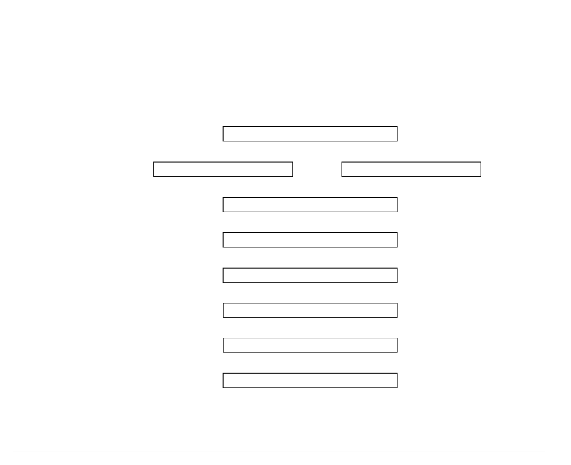
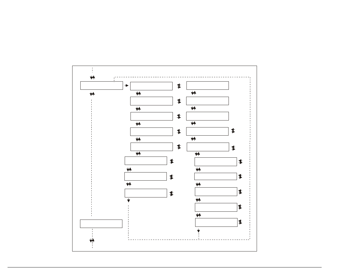
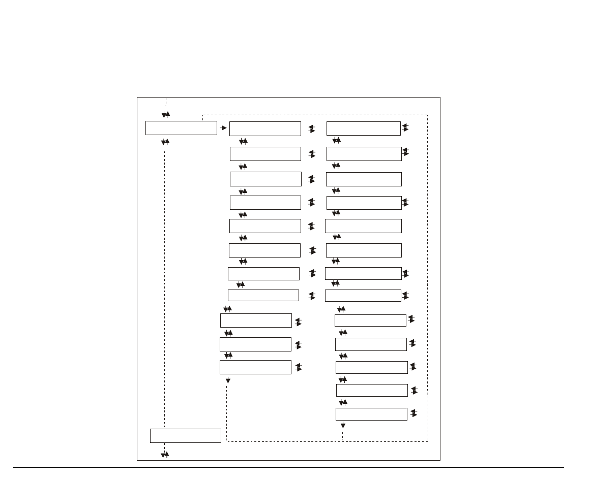
The following figure shows the structure of the Power-On Configuration and how to move inside
the Setup.
34
Main Structure
Upp. Jam Sens. Y
Parall Interface
Serial Interface
Functions
Back to MFG? NO
Print out? NO Print out? YES
Low. Jam Sens. Y
Upp. Jam Sens. N
Back to MFG? YES
Parallel Interface Settings
Serial Interface Settings
Functions Block
Low. Jam Sens. N
The functions concerning the interfaces group the parameters for the configuration of the
interfaces.
The setup item Functions groups the following printer functions:
• Paper overlay (9078 plus model only),
• Paper loading sequence,
• Buzzer setting,
• Quick cut sheet loading (9078 plus model only),
• Ribbon type,
• Code bar density,
• Text printing direction,
• Graphics printing direction,
• Bar code printing direction,
• Paper path at power on,
• Language of the display messages.
35
Printout of the Printer Settings
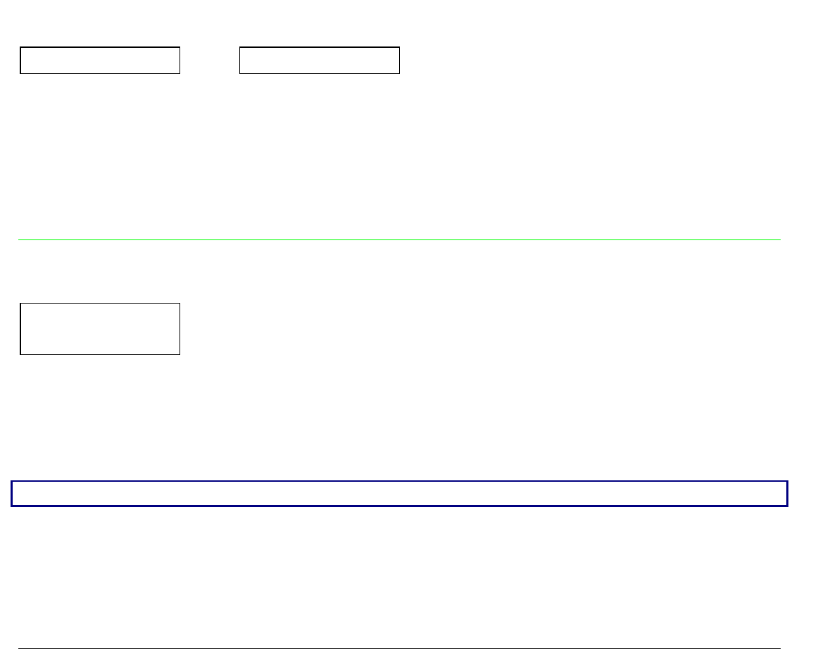
PRINT OUT? NO → or ← PRINT OUT? YES
↓
LOW.JAM SENS.Y
PRINT OUT? NO The Setup is not printed.
PRINT OUT? YES The printer setup is printed showing the currently selected values. The printout
starts as soon as you select this value.
Enable/Disable Lower Tractor Jam Sensor
PRINT OUT? NO
↑
LOW. JAM SENS. Y → or ←
LOW. JAM SENS. N → or ←
↓
UPP. JAM SENS. Y
LOW. JAM SENS. Y Enables the paper jam sensor located in the Lower Push Tractor.
LOW. JAM SENS. N Disables the paper jam sensor located in the Lower Push Tractor.
When the cutter option is used, the jam sensor should be enabled for higher cut precision.

36
Enable/Disable Upper Tractor Jam Sensor (only 9078D model)
LOW. JAM SENS. Y
↑
UPP. JAM SENS. Y → or ←
UPP. JAM SENS. N → or ←
↓
PARALL INTERFACE
UPP. JAM SENS. Y Enables the paper jam sensor located in the Upper Push Tractor.
UPP. JAM SENS. N Disables the paper jam sensor located in the Upper Push Tractor.
When the cutter option is used, the jam sensor should be enabled for higher cut precision.
37
Parallel Interface
This menu defines the use of the parallel interface and is structured according to the interface
specific parameters.
Parallel Interface Parameters
CX Parallel I/F
Select-In On
Data Bits 7
Dedic. Buffer ...
Emul. IBM ...
Parall.Interface
Char. Set ...
Nation ...
Serial Interface
Auto LF ...
Char. Set ...
Nation ...
Auto CR ...
Auto LF ...
20 CPI IBM ...
1284 Bidir. I/F
Data Bits 8
Dedic. Buffer 2K
Select-In Host
Emul EPSON

38
Setting the Interface Parameters
Interface Type
UPP. JAM SENSOR Y PARALL INTERFACE
↓ ↑
PARALL INTERFACE → 1284 BIDIR I/F → or ←
CX PARALLEL I/F → or ←
↓ ↓
SERIAL INTERFACE SELECT-IN HOST
1284 BIDIR i/F Bidirectional IEEE 1284 parallel interface.
CX PARALLEL I/F Centronics type parallel interface (monodirectional)
Setting the Select-In Signal
1284 BIDIR. I/F
↑
SELECT-IN HOST → or ←
SELECTIN ON → or ←
↓
DATA BITS 8
SELECT-IN ON The SELECT-IN signal of the parallel interface is ignored and treated always as
ON.
SELECT-IN HOST The printer checks the SELECT-IN signal coming from the host.

39
Number of Data Bits
SELECT-IN HOST
↑
DATA BITS 8 → or ←
DATA BITS 7 → or ←
↓
DEDIC.BUFFER 2K
Selection of the number of data bits: 7 or 8
Input Buffer Size
DATA BITS 8
↑
DEDIC.BUFFER 256 → or ←
DEDIC.BUFFER 2K → or ←
DEDIC.BUFFER 12K → or ←
DEDIC.BUFFER 32K → or ←
DEDIC.BUFFER 64K → or ←
↓
EMUL. EPSON LQ
Selects the input buffer size. If the input buffer is set to 64K, the DLL is not available.

40
Printer Emulation
DEDIC.BUFFER 2K
↑
EMUL. EPSON LQ → or ←
EMUL. IBM XL24 → or ←
EMUL. IBM XL24AGM → or ←
EMUL. IBM 2391 → or ←
↓
CHAR. SET CS2
EMUL. EPSON LQ The printer uses the EPSON LQ 1050/2550 emulation.
EMUL. IBM XL24 The printer uses the IBM Proprinter XL24e emulation.
EMUL. IBM XL24AGM The printer uses the IBM Proprinter XL24 AGM emulation.
EMUL. IBM 2391 The printer uses the IBM Personal 2391+ emulation.
EPSON Character Sets
EMUL. EPSON LQ
↑
CHAR. SET CS1 → or ←
CHAR. SET CS2 → or ←
CHAR. SET ITALIC → or ←
↓
NATION CP437
These items select the character set to be used in EPSON emulation.

41
IBM Character sets
EMUL. IBM xxx
↑
CHAR. SET CS1 → or ←
CHAR. SET CS2 → or ←
↓
NATION CP437
These items select the character set to be used in IBM Proprinter emulation.
EPSON National Character sets
CHAR. SET CS2
↑
NATION CP437 → or ←
NATION ... → or ←
NATION LATIN A1 → or ←
↓
AUTO LF NO
The following national character sets are available:
CP 437 CP437 G 96 GREEK CP850 CP851
CP 852 CP 853 CP 855
CP 857 CP 858 CP 860
CP 862 CP 863 CP 864 CP 865 CP 866
CP 867 CP 876 CP 877 CP 1250 CP 1251 CP 1252 GOST TASS
MAZOWIA ISO 8859/1 ISO 8859/2 ISO 8859/3 ISO 8859/4 ISO 8859/5 ISO 8859/6 ISO 8859/7
ISO 8859/8 ISO 8859/9 ISO 8859/15 USA FRANCE GERMANY ENGLAND DENMARK1
SWEDEN ITALY SPAIN1 JAPAN NORWAY DENMARK2 SPAIN2 LATIN A1
The CP 858 and ISO 8859/15 character sets contain the Euro character.

42
IBM National Character Sets
CHAR. SET CS2
↑
NATION CP437 → or ←
NATION ... → or ←
NATION 8859/15 → or ←
↓
AUTO CR NO
The following national character sets can be selected:
CP 437 CP437 G 96 GREEK CP850 CP851
CP 852 CP 853 CP 855
CP 857 CP 858 CP 860
CP 862 CP 863 CP 864 CP 865 CP 866
CP 867 CP 876 CP 877 CP 1250 CP 1251 CP 1252 GOST TASS
MAZOWIA ISO 8859/1 ISO 8859/2 ISO 8859/3 ISO 8859/4 ISO 8859/5 ISO 8859/6 ISO 8859/7
ISO 8859/8 ISO 8859/9 ISO 8859/15
The CP 858 and ISO 8859/15 character sets contain the Euro character.

43
CR Code Behavior
These items are displayed only if the IBM emulation is selected.
NATION xxx
↑
AUTO CR NO → or ←
AUTO CR YES → or ←
↓
AUTO LF NO
AUTO CR NO No automatic carriage return is performed after a LF, VT or ESCJ code.
AUTO CR YES The printer performs an automatic carriage return after a LF, VT or ESCJ code .
LF Code Behavior
AUTO CR NO
or
NATION CP437
↑
AUTO LF NO → or ←
AUTO LF YES → or ←
AUTO LF HOST → or ←
↓
20 CPI IBM NO
or
PARALL INTERFACE
AUTO LF NO No Automatic LF after CR.
AUTO LF YES Automatic LF after CR.
AUTO LF HOST Only in EPSON emulation. The printer checks the AUTOFEEDXT signal coming
from the host and executes an automatic LF after CR, if the signal is low.

44
IBM Compressed Printing
These items are displayed only, if the IBM emulation is selected.
AUTO LF NO
↑
20 CPI IBM NO → or ←
20 CPI IBM YES → or ←
↓
PARALL INTERFACE
20 CPI IBM NO The compressed printing is performed at 17,1 cpi.
20 CPI IBM YES The compressed printing is performed at 20 cpi.
45
Serial Interface
This menu defines the use of the serial interface and is structured according to the interface
specific parameters.
Serial Interface Parameters
Serial I/F No
Baud 9600
Data Bits 8
Parity None
Handshake DTR
Serial I/F ...
Baud ...
Data Bits 7
Parity ...
Handshake Xon/Xof
Serial Interface
Connection Local
Dedic. Buffer 2K
Emul. EPSON
Functions
Connect. Remote
Dedic. Buffer ...
Emul. IBM ...
Char. Set...
20 CPI IBM ...
Char. Set ...
Nation ...
Auto LF ...
Auto LF ...
Auto CR ...
Nation ...

46
Setting the Interface Parameters
Interface Type
PARALL INTERFACE SERIAL INTERFACE
↑ ↑
SERIAL INTERFACE → SERIAL I/F NO → or ←
SERIAL I/F 232 → or ←
SERIAL I/F 422 → or ←
↓ ↓
FUNCTIONS BAUD 9600
SERIAL I/F NO The serial interface is disabled
SERIAL I/F 232 Defines the usage of the serial interface RS-232/C
SERIAL I/F 422 Defines the usage of the serial interface RS-422/A

47
Baud Rate
SERIAL I/F NO
↑
BAUD 300 → or ←
BAUD 600 → or ←
BAUD 1200 → or ←
BAUD 2400 → or ←
BAUD 4800 → or ←
BAUD 9600 → or ←
BAUD 19200 → or ←
BAUD 38400 → or ←
↓
DATA BITS 8
The baud rate is selected in bits per second. The above values can be selected.
Number of Data Bits
BAUD 9600
↑
DATA BITS 8 → or ←
DATA BITS 7 → or ←
↓
PARITY NONE
Selection of the number of data bits: 7 or 8.

48
Parity Check
DATA BITS 8
↑
PARITY NONE → or ←
PARITY ODD → or ←
PARITY EVEN → or ←
PARITY MARK → or ←
PARITY SPACE → or ←
↓
HANDSHAKE DTR
PARITY NONE Data does not have a parity bit, i.e. 8 bit data are transferred and the parity check
is disabled.
PARITY ODD Parity check is enabled for odd parity.
PARITY EVEN Parity check is enabled for even parity.
PARITY MARK Parity check is disabled and the transmitted parity bit is always a Mark.
PARITY SPACE Parity check is disabled and the transmitted parity bit is always a Space.

49
Handshake Protocol
PARITY NONE
↑
HANDSHAKE DTR → or ←
HANDSHAKE XONXOF → or ←
↓
CONNECTION LOCAL
HANDSHAKE DTR The Handshake is performed using the DTR Protocol.
HANDSHAKE XONXOF The Handshake is performed using the XON-XOFF Protocol.
Connection Type
HANDSHAKE DTR
↑
CONNECTION LOCAL → or ←
CONNECT. REMOTE → or ←
↓
DEDIC.BUFFER 2K
Selects the connection type: local or remote.

50
Input Buffer Size
DATA BITS 8
↑
DEDIC.BUFFER 256 → or ←
DEDIC.BUFFER 2K → or ←
DEDIC.BUFFER 12K → or ←
DEDIC.BUFFER 32K → or ←
DEDIC.BUFFER 64K → or ←
↓
EMUL. EPSON LQ
Selects the input buffer size. If the input buffer is set to 64K, the DLL is not available.
Printer Emulation
DEDIC.BUFFER 2K
↑
EMUL. EPSON LQ → or ←
EMUL. IBM XL24 → or ←
EMUL. IBM XL24AGM → or ←
EMUL. IBM 2391 → or ←
↓
CHAR. SET CS2
EMUL. EPSON LQ The printer uses the EPSON LQ 1050/2550 emulation.
EMUL. IBM XL24 The printer uses the IBM Proprinter XL24e emulation.
EMUL. IBM XL24AGM The printer uses the IBM Proprinter XL24 AGM emulation.
EMUL. IBM 2391 The printer uses the IBM Personal 2391 + emulation.

51
EPSON Character Sets
EMUL. EPSON LQ
↑
CHAR. SET CS1 → or ←
CHAR. SET CS2 → or ←
CHAR. SET ITALIC → or ←
↓
NATION CP437
These items select the character set to be used in EPSON emulation.
IBM Character sets
EMUL. IBM xxx
↑
CHAR. SET CS1 → or ←
CHAR. SET CS2 → or ←
↓
NATION CP437
These items select the character set to be used in IBM Proprinter emulation.
52
EPSON National Character sets
CHAR. SET CS2
↑
NATION CP437 → or ←
NATION ... → or ←
NATION LATIN A1 → or ←
↓
AUTO LF NO
The following national character sets are available:
CP 437 CP437 G 96 GREEK CP850 CP851
CP 852 CP 853 CP 855
CP 857 CP 858 CP 860
CP 862 CP 863 CP 864 CP 865 CP 866
CP 867 CP 876 CP 877 CP 1250 CP 1251 CP 1252 GOST TASS
MAZOWIA ISO 8859/1 ISO 8859/2 ISO 8859/3 ISO 8859/4 ISO 8859/5 ISO 8859/6 ISO 8859/7
ISO 8859/8 ISO 8859/9 ISO 8859/15 USA FRANCE GERMANY ENGLAND DENMARK1
SWEDEN ITALY SPAIN1 JAPAN NORWAY DENMARK2 SPAIN2 LATIN A1
The CP 858 and ISO 8859/15 character sets contain the Euro character.

53
IBM National Character Sets
CHAR. SET CS2
↑
NATION CP437 → or ←
NATION ... → or ←
NATION 8859/15 → or ←
↓
AUTO CR NO
The following national character sets can be selected:
CP 437 CP437 G 96 GREEK CP850 CP851
CP 852 CP 853 CP 855
CP 857 CP 858 CP 860
CP 862 CP 863 CP 864 CP 865 CP 866
CP 867 CP 876 CP 877 CP 1250 CP 1251 CP 1252 GOST TASS
MAZOWIA ISO 8859/1 ISO 8859/2 ISO 8859/3 ISO 8859/4 ISO 8859/5 ISO 8859/6 ISO 8859/7
ISO 8859/8 ISO 8859/9 ISO 8859/15
The CP 858 and ISO 8859/15 character sets contain the Euro character.

54
CR Code Behavior
These items are displayed only if the IBM emulation is selected.
NATION xxx
↑
AUTO CR NO → or ←
AUTO CR YES → or ←
↓
AUTO LF NO
AUTO CR NO No automatic carriage return is performed after a LF, VT or ESCJ code.
AUTO CR YES The printer performs an automatic carriage return after a LF, VT or ESCJ code .
LF Code Behavior
AUTO CR NO
or
NATION CP437
↑
AUTO LF NO → or ←
AUTO LF YES → or ←
↓
20 CPI IBM NO
or
SERIAL INTERFACE
AUTO LF NO No Automatic LF after CR.
AUTO LF YES Automatic LF after CR.

55
IBM Compressed Printing
These items are displayed only, if the IBM emulation is selected.
AUTO LF NO
↑
20 CPI IBM NO → or ←
20 CPI IBM YES → or ←
↓
SERIAL INTERFACE
20 CPI IBM NO The compressed printing is performed at 17,1 cpi.
20 CPI IBM YES The compressed printing is performed at 20 cpi.
56
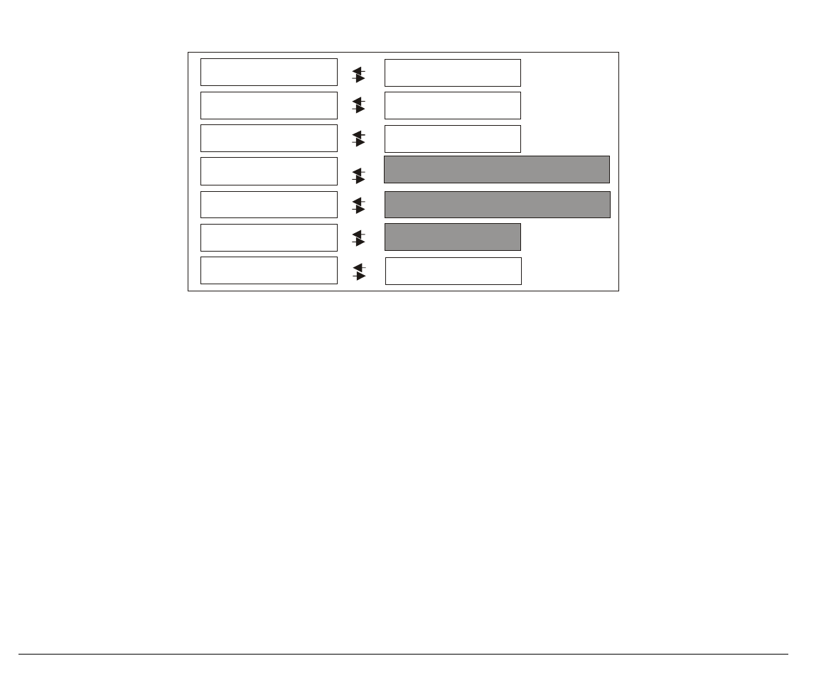
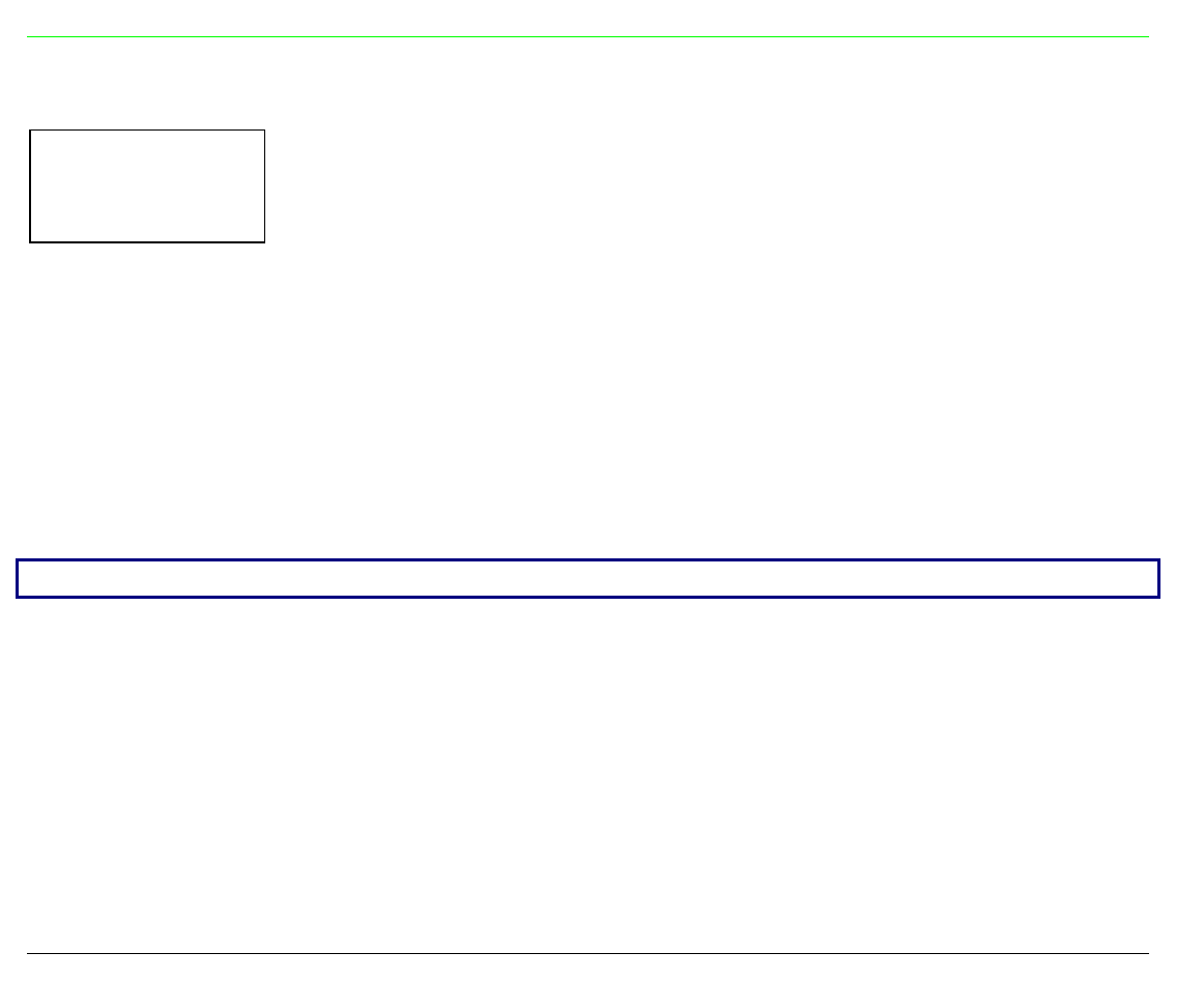
Functions
This item groups various printer functions, with which you can configure the printer.
9078 plus model
Sequence None
Buzzer Yes
Quick Yes
Ribbon Black
Bar Codes 60
Text Direct Bi
Graph Direct Bi
Bar Code Bi
P.On Path Macro
Menu ENGLISH
Sequence ...
Buzzer No
Ribbon Color
Text Direct Uni
Graph Direct Uni
Bar Code Uni
P.On Path Last
Menu …
Paper Overly? No Paper Overly? Yes
Bar Codes 90
Quick No
Back to Mfg? No
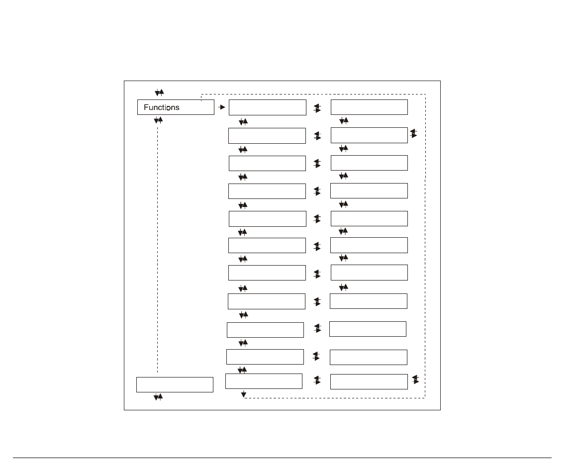
57
9078D plus model
Sequence None
Buzzer Yes
Ribbon Black
Bar Codes 60
Text D irect Bi
Graph Direct Bi
Bar Code Bi
P.On Path Macro
Menu ENGLISH
Sequence ...
Buzzer No
Ribbon Color
Text D irect U ni
Graph Direct Uni
Bar Code Uni
P.On Path Last
Menu …
Bar Codes 90
58
Setting the Functions Group Items
SERIAL INTERFACE FUNCTIONS
↑ ↑
FUNCTIONS → PAPER OVERLY NO 9078 plus
SEQUENCE NONE 9078D plus
↓ ↓
BACK TO MFG: NO SEQUENCE NONE
or
BUZZER YES
9078 plus
9078D plus
Paper Overlapping (9078 plus model only)
FUNCTIONS
↑
PAPER OVERLY NO → or ←
PAPER OVERLY YES → or ←
↓
SEQUENCE NONE
PAPER OVERLY NO When feeding a cut sheet through the manual entry slot, the fanfold paper
must be parked.
PAPER OVERLY YES A single sheet can be fed simultaneously with a fanfold.
If the printer is using the Push Pull paper feed mode the Overlay Function cannot be selected.
Only the Paper Overly No item appears.

59
Paper Loading Sequence
FUNCTIONS (9078D plus model)
or
PAPER OVERLY NO (9078 plus model)
↑
SEQUENCE NONE → or ←
SEQ. L + U PUSH (9078D plus model only) → or ←
SEQUENCE ASF1+2 → or ←
SEQUENCE ASF123 → or ←
↓
BUZZER YES
These items are displayed only, if the accessories to which they refer are installed.
SEQUENCE NONE The paper is fed only through the path selected by operator panel.
SEQ. L + U PUSH The paper is fed firstly through the lower push path and successively through
the upper push path (9078D plus model only).
SEQUENCE ASF1+2 This item appears only, if the automatic sheet feeder is installed. The paper is
fed from the first bin until this bin is out of paper. Then the paper is fed from
the second bin.
SEQUENCE ASF123 This item appears only, if the automatic sheet feeder is installed. The paper is
fed from the first bin until this bin is out of paper. Then the paper is fed from
the second bin and finally from the third bin.

60
Enable/Disable the Buzzer
SEQUENCE NONE
↑
BUZZER YES → or ←
BUZZER NO → or ←
↓
QUICK YES (9078 plus model)
or
BLACK RIBBON (9078D plus model)
Enable or disables the buzzer.
Quick Manual Loading through the Manual Slot (9078 plus model only)
BUZZER YES
↑
QUICK NO → or ←
QUICK YES → or ←
↓
RIBBON BLACK
QUICK NO The single sheet in the manual path is loaded by the operator. The printer is then
disabled.
QUICK YES The single sheet in the manual path is loaded automatically. The printer is then
enabled.

61
Ribbon Type Selection
QUICK YES (9078 plus model)
or
BUZZER YES (9078D plus model)
↑
RIBBON BLACK → or ←
RIBBON COLOR → or ←
↓
BAR CODE 60DPI
Selects the ribbon type to be used with the printer: black or color.
Bar Code Density
RIBBON BLACK
↑
BAR CODE 60DPI → or ←
BAR CODE 90DPI → or ←
↓
TEXT DIRECT BI
Selects the bar code print density: 60 or 90 dpi.
Text Print Direction
BAR CODE 60DPI
↑
TEXT DIRECT BI → or ←
TEXT DIRECT UNI → or ←
↓
GRAPH DIRECT BI
Selects the print direction for text: bidirectional or unidirectional.

62
Graphics Print Direction
TEXT DIRECT BI
↑
GRAPH DIRECT BI → or ←
GRAPH DIRECT UNI → or ←
↓
BARCODES DIR.UNI
Selects the print direction for graphics: bidirectional or unidirectional.
Bar Codes Print Direction
GRAPH DIRECT BI
↑
BARCODES DIR.BI → or ←
BARCODES DIR.UNI → or ←
↓
P. ON PATH MACRO
Selects the print direction for bar codes: bidirectional or unidirectional.
63
Paper Path at Power-On
BARCODES DIR.UNI
↑
P. ON PATH MACRO → or ←
P. ON PATH LAST → or ←
↓
MENU ENGLISH
P. ON PATH MACRO The paper path at power-on is the one from the default Macro.
P. ON PATH LAST The paper path at power-on is the last one that was selected before the printer
was powered off.
Selection of the Language of the Display Messages
P. ON PATH MACRO
↑
MENU ENGLISH → or ←
MENU ITALIANO → or ←
MENU FRANCAIS → or ←
MENU ESPANOL → or ←
MENUE DEUTSCH → or ←
↓
FUNCTIONS
These items are self explaining.
See also “Selecting the Display Language” before in this manual.

64
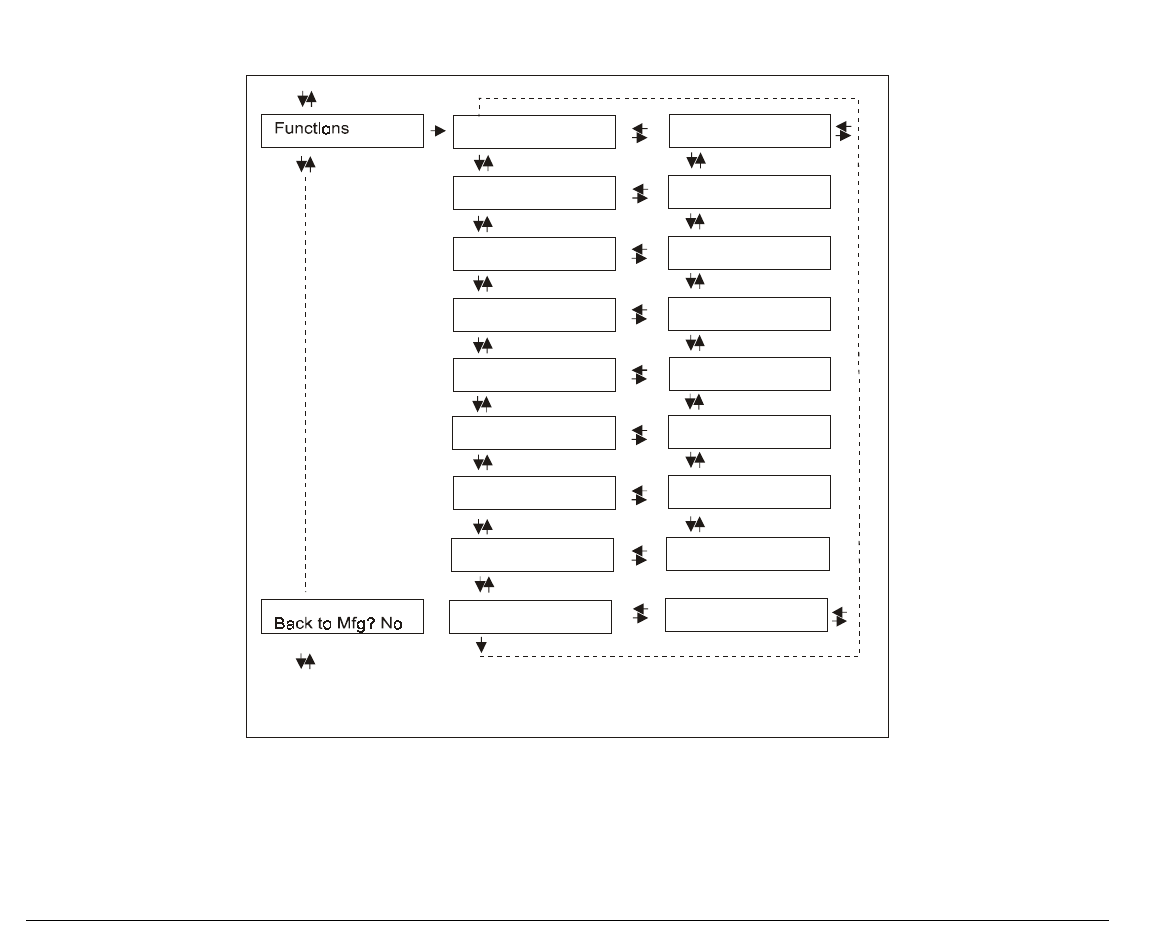
Resetting to Factory Default Values
With the BACK TO MFG function it is possible to reset all items in the Power On Configuration
and in the Program Setup to their factory default values. This may be useful if you do not
remember the values you set in the menus, or because you simply changed you mind about the
settings you have just done. The default values for the menu items are indicated in bold
FUNCTIONS
↑
BACK TO MFG: NO → or ← BACK TO MFG: YES
↓ or PROG
PRINT OUT ? NO
If you want to select BACK TO MFG:YES, you have to exit from this item using the ↑ or the ↓
key, in order to confirm the selection of this value.
At this point, the Power On Configuration Setup procedure is finished. If you exit pressing the ↓
and the PROGRAM key, the new settings will be saved.
Do not power off the printer before all data have been written into the NVM and the printer has
returned online.