Computer Process Controls 809-3542 RF ambient temperature sensor User Manual RF Sensor
Computer Process Controls Inc. RF ambient temperature sensor RF Sensor
users manual

026-1702 Rev 0 10-30-00
Radio Frequency (RF)
Temperature Sensor System
Installation and Operation
Manual

1640 Airport Road, Suite 104
Kennesaw, GA 31044
Phone: (770) 425-2724
Fax: (770) 425-9319
ALL RIGHTS RESERVED.
The information contained in this manual has been carefully checked and is believed to be accurate. However, Com-
puter Process Controls, Inc. assumes no responsibility for any inaccuracies that may be contained herein. In no event will
Computer Process Controls, Inc. be liable for any direct, indirect, special, incidental, or consequential damages resulting
from any defect or omission in this manual, even if advised of the possibility of such damages. In the interest of continued
product development, Computer Process Controls, Inc. reserves the right to make improvements to this manual, and the
products described herein, at any time without notice or obligation.
FCC COMPLIANCE NOTICE
NOTE: This equipment has been tested and found to comply with the limits for a Class B digital device, pursuant to
Part 15 of the FCC Rules. These limits are designed to provide reasonable protection against harmful interference in a res-
idential installation. This equipment generates, uses, and can radiate radio frequency energy and, if not installed and used
in accordance with the instructions, may cause harmful interference to radio communications. However, there is no guar-
antee that interference will not occur in a particular installation. If this equipment does cause harmful interference to radio
or television reception, which can be determined by turning the equipment off and on, the user is encouraged to try and
correct the interference by one or more of the following measures:
-- Reorient or relocate the receiving antenna
-- Increase the separation between the equipment and the receiver
-- Connect the equipment into an outlet on a circuit different from that to which the receiver is connected
-- Consult the dealer or an experienced radio/TV technician for help
READ ALL INSTRUCTIONS CAREFULLY before attempting to install or operate the RF Sensor Sys-
tem.
SAVE THIS INSTRUCTION MANUAL — This instruction manual contains important operating instruc-
tions for the RF Sensor System.
Warning! FCC Regulations state that any unauthorized
changes or modifications to this equipment not expressly ap-
proved by the manufacturer could void the user's authoriza-
tion to operate this equipment.

Table of Contents • 1
Table of Contents
1 OVERVIEW................................................................................................................................................................... 1
1.1. SYSTEM DESCRIPTION .................................................................................................................................................. 1
1.2. HARDWARE COMPONENTS ........................................................................................................................................... 3
1.2.1. Sensors .................................................................................................................................................................. 3
1.2.1.1. RF Ambient Temperature Sensors...................................................................................................................................... 3
1.2.1.2. RF Long-Range Ambient Sensors...................................................................................................................................... 4
1.2.1.3. RF Product Simulator ......................................................................................................................................................... 4
1.2.2. RF Receiver........................................................................................................................................................... 5
1.2.3. RF Gateway........................................................................................................................................................... 5
1.2.4. Hand-Held Terminal............................................................................................................................................. 6
2 INSTALLING THE RF GATEWAY........................................................................................................................... 7
2.1. MOUNTING THE RF GATEWAY..................................................................................................................................... 7
2.2. POWERING THE RF GATEWAY ..................................................................................................................................... 7
2.3. WIRING THE RF GATEWAY TO A CPC SITE CONTROLLER (I/O NETWORK)................................................................ 8
2.3.1. Wire Connection ................................................................................................................................................... 8
2.3.2. Setting the Board Numbering Dip Switch............................................................................................................. 8
2.3.3. Setting the Baud Rate Dip Switch ......................................................................................................................... 9
2.3.4. Setting the RS485 I/O Termination Jumpers......................................................................................................... 9
2.4. NETWORKING GATEWAYS AND RECEIVERS (TOKEN RING NETWORK) ..................................................................... 10
2.4.1. Wiring the Token Ring Network to the Gateway................................................................................................. 10
2.4.2. Setting the Token Ring Network Termination Jumpers ...................................................................................... 10
3 INSTALLING THE RF RECEIVER......................................................................................................................... 11
3.1. MOUNTING AND PLACEMENT OF THE RF RECEIVER.................................................................................................. 11
3.1.1. Environmental Operating Conditions................................................................................................................. 11
3.1.2. Placement............................................................................................................................................................ 11
3.1.3. Mounting............................................................................................................................................................. 11
3.2. POWERING THE RF RECEIVER .................................................................................................................................... 11
3.3. WIRING THE RF RECEIVER TO A CPC SITE CONTROLLER......................................................................................... 11
3.3.1. Wire Connection ................................................................................................................................................. 12
3.3.2. Setting the Token Ring Network Termination Jumpers ...................................................................................... 12
3.3.3. Setting the Receiver Numbering Dip Switch....................................................................................................... 12
3.3.4. Setting the Baud Rate Dip Switch ....................................................................................................................... 13
4 INSTALLING THE RF SENSOR.............................................................................................................................. 14
4.1. PLACEMENT OF RF SENSORS...................................................................................................................................... 14
4.1.1. RF (Short-Range) Ambient Sensor...................................................................................................................... 14
4.1.2. RF Long-Range Transmitter............................................................................................................................... 14
4.1.3. RF Product Simulator ......................................................................................................................................... 14
4.2. ACTIVATION ............................................................................................................................................................... 14
4.2.1. Verifying Active State.......................................................................................................................................... 14
4.3. CLEAN SWITCH AND DEFROST TERMINATION WIRING.............................................................................................. 14
5 COMMISSIONING THE RF SENSORS.................................................................................................................. 16
5.1. WHAT IS COMMISSIONING? ........................................................................................................................................ 16
5.2. MANUAL ENTRY METHOD ......................................................................................................................................... 16
5.2.1. Entering the ID Numbers on the RF Gateway .................................................................................................... 17
5.3. SERVICE PIN METHOD................................................................................................................................................ 18

2 • RF Sensor System I&O Manual 026-1702 Rev 0 10-30-00
5.3.1. Setting up the RF Gateway to Receive ID Transmissions ................................................................................... 18
5.3.2. Hand-Held Terminal Screen Navigation Tips..................................................................................................... 19
5.4. VERIFYING SUCCESSFUL COMMISSIONING ................................................................................................................. 19
5.5. DECOMMISSIONING A SENSOR FROM THE RF GATEWAY ........................................................................................... 19
5.5.1. Decommissioning Manually Entered ID Numbers.............................................................................................. 19
5.5.2. Decommissioning ID Numbers Entered By Service Pin ..................................................................................... 20
6 CONNECTING SENSORS TO EINSTEIN/REFLECS........................................................................................... 21
7 OPERATION AND MAINTENANCE OF THE RF SENSOR SYSTEM.............................................................. 22
7.1. STATUS LEDS............................................................................................................................................................. 22
7.1.1. RF Sensors........................................................................................................................................................... 22
7.1.2. RF Receivers ....................................................................................................................................................... 22
7.1.2.1. The Status LED................................................................................................................................................................. 22
7.1.2.2. The RF LED...................................................................................................................................................................... 22
7.1.2.3. The Token Ring LED ....................................................................................................................................................... 22
7.1.3. RF Gateway......................................................................................................................................................... 23
7.1.3.1. The General Status LED ................................................................................................................................................... 23
7.1.3.2. The Alarm LED ................................................................................................................................................................ 23
7.1.3.3. RS485 I/O Network Status LED....................................................................................................................................... 23
7.1.3.4. Token Ring Network Status LED..................................................................................................................................... 23
7.2. CLEAN SWITCH OPERATION ....................................................................................................................................... 23
7.2.1. Internal Clean Switch.......................................................................................................................................... 24
7.2.2. External Clean Switch......................................................................................................................................... 24
7.3. BATTERY LIFE AND REPLACEMENT............................................................................................................................ 24
7.3.1. Reactivating the RF Sensor................................................................................................................................. 24
7.4. VIEWING STATUS USING THE HAND-HELD TERMINAL.............................................................................................. 24
7.4.1. Viewing Update Counts....................................................................................................................................... 25
7.4.1.1. Resetting the Sensor Update Count.................................................................................................................................. 26
7.5. RF SENSOR SLEEP MODE ........................................................................................................................................... 26

Overview • 1
1Overview
CPC’s Radio Frequency (RF) Sensor System
provides refrigerated case temperature monitor-
ing and control without the time and expense
required to wire multiple temperature sensors
from the cases back to the area controllers. All
sensors in the RF Sensor System family are
completely wireless, transmitting their values to
receivers in the store area that pass them back to
the area controllers.
Figure 1-1 - RF System Diagram
2 • RF Sensor System I&O Manual 026-1702 Rev 0 10-30-00
1.1. Hardware Components
1.1.1. Sensors
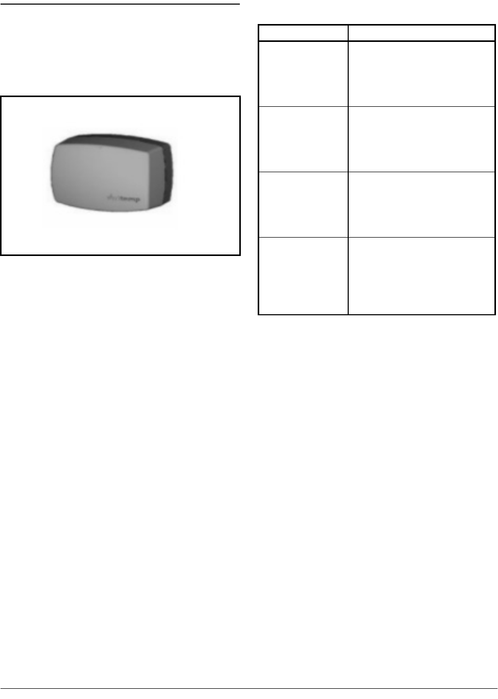
1.1.1.1. RF Ambient Temperature Sen-
sors
The RF Ambient Temperature Sensor is an
enclosure with a built-in broadcast antenna. This
sensor may be mounted anywhere within a
refrigerated case, as long as it is within 150 feet
of an RF Receiver and within a clear line of sight
to the receiver’s antenna.
Four models of the RF Ambient Temperature
Sensor are available. Each model has either
internal or external temperature sensing ele-
ments, and either clean switch or defrost termi-
nation digital inputs. Table 1-1 lists all RF
Ambient Temperature Sensor models along with
their characteristics.
Figure 1-2 - Ambient Temperature Sensor (Internal Model
Shown)
Part Number Description
809-3542 RF Internal Ambient Sensor, w/
sensor element mounted inside
enclosure, and with a built-in clean
switch button for alarm suspension
during cleaning
809-3544 RF External Ambient Sensor, w/
external NSF-approved stainless
steel bullet sensor and neoprene
leads, with external leads for con-
nection to clean switch
809-3552 RF Internal Ambient Sensor, w/
sensor element mounted inside
enclosure and external leads for
connection to digital defrost termi-
nation sensor
809-3550 RF External Ambient Sensor, w/
external NSF-approved stainless
steel bullet sensor and neoprene
leads, with external leads for con-
nection to digital defrost termina-
tion sensor
Table 1-1 - RF Ambient Sensor Models
Hardware Components Overview • 3
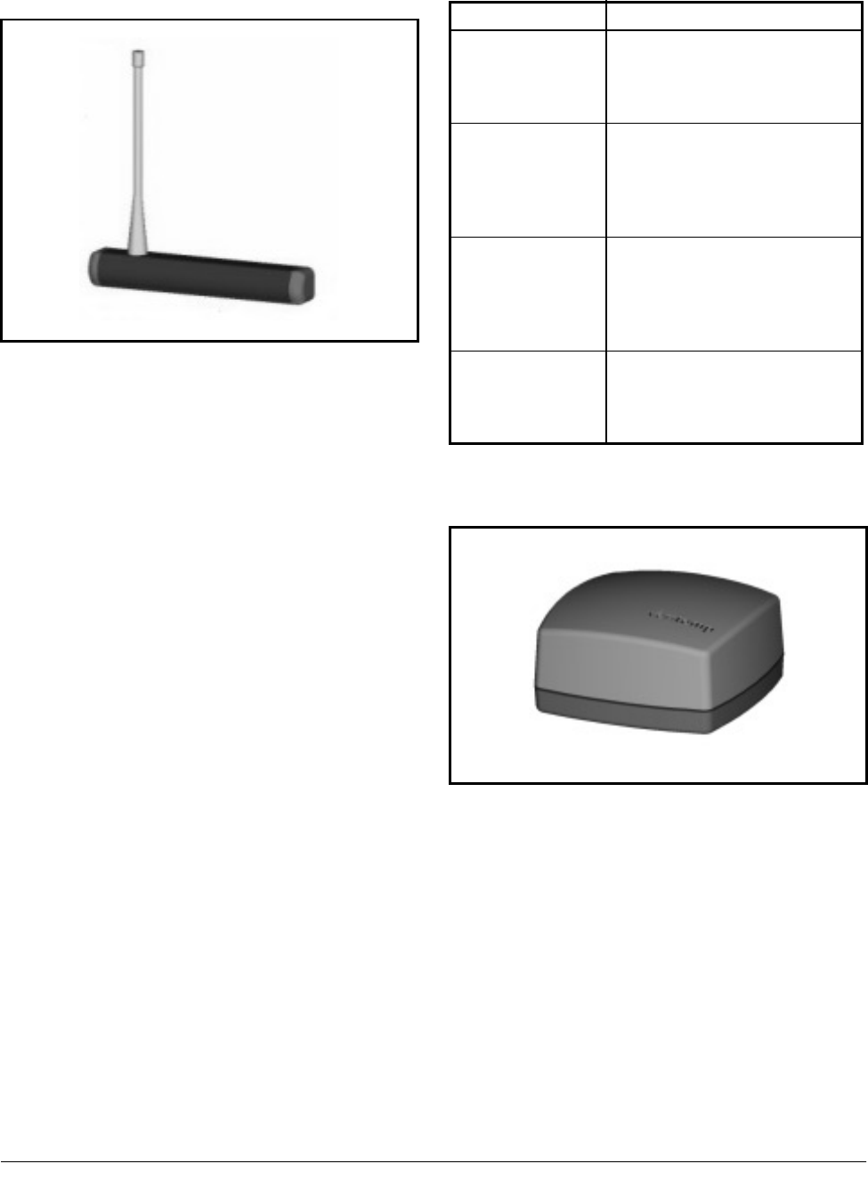
1.1.1.2. RF Long-Range Ambient Sen-
sors
The RF Long-Range Ambient Sensor
improves on the 150 feet transmitter-to-receiver
maximum distance of the other internal & exter-
nal sensor models. The cylindrical enclosure
holds a “whip” antenna capable of transmitting
to receivers as far away as 200 feet.
Like the shorter-range sensors described in
Section 1.2.1.1., there are both internal and
external models of the long-range sensors, both
with either clean switch or digital defrost termi-
nation inputs. Table 1-2 lists each long-range
sensor model.
1.1.1.3. RF Product Simulator
The RF Product Simulator (P/N 809-3548)
mimics the thermal characteristics of product
within refrigerated cases or freezers. Tempera-
ture readings from product simulators can be
used to verify product remains within acceptable
food safety levels.
Figure 1-3 - Long-Range Ambient Sensor Enclosure
Part Number Description
809-3543 Long-Range Internal Ambient
Sensor, w/ internal temperature
sensor element and clean switch
button
809-3545 Long-Range External Ambient
Sensor, w/ NSF approved stainless
steel bullet sensor and neoprene
leads, with external leads for clean
switch
809-3549 Long-Range External Ambient
Sensor, w/ NSF approved stain-
less steel bullet sensor and neo-
prene leads, with external leads for
digital defrost termination sensor
809-3551 Long-Range Internal Ambient
Sensor, w/ internal sensor element
and external leads for digital
defrost termination sensor
Table 1-2 - Long-Range RF Ambient Sensor Models
Figure 1-4 - RF Product Simulator

4 • RF Sensor System I&O Manual 026-1702 Rev 0 10-30-00
The sensing element and transmitting
antenna for the RF Product Sensor are inside the
enclosure and may transmit to receivers up to
150 feet away. The sensor also has an internal
clean switch, which is activated by pressing a
button on the enclosure.
1.1.2. RF Receiver
The RF Receiver (P/N 837-3510) is an
antenna that mounts to the ceiling of the sales
area or on top of a refrigerated case. The RF
Receiver accepts transmissions from RF Ambi-
ent Temperature Sensors and RF Product Simu-
lators. It passes the sensor readings it receives to
the RF Gateway by way of an RS485 network
connection.
Up to six RF Receivers may be mounted
within a single building.
1.1.3. RF Gateway
The RF Gateway (P/N 810-3500) is an
RS485 peripheral board compatible with both
Einstein and REFLECS (RMCC, BEC, and
BCU) systems. The RF Gateway serves as an
interface between the RF Receivers, which send
messages from the sensors, and the area control-
lers, which use the sensor values for logging,
controlling, and alarming. Each Einstein or
REFLECS controller that will read values from
RF Sensors must be equipped with an RF Gate-
way.
Sensors and product simulators that will be
used by an Einstein must be “commissioned” in
the RF Gateway’s software. Once a sensor is
commissioned, the gateway then assigns the sen-
sor to a virtual "board and point" address. This
allows the area controller to tie application
inputs to RF Sensor values in the same way tra-
ditional 16AI board and point inputs are set up.
Figure 1-5 - RF Receiver
Figure 1-6 - RF Gateway Board
6 • RF Sensor System I&O Manual 026-1702 Rev 0 10-30-00
2 Installing the RF Gate-
way
Installing the RF Gateway device for a site
controller involves mounting and powering the
device, connecting to the CPC controller’s
RS485 network, and networking the RF Gate-
way with other gateways and receivers on-site.
2.1. Mounting the RF Gate-
way
The RF Gateway is typically mounted in the
same area as the site controller, near the control-
ler’s 16AI, 8RO, and other RS485 network
peripherals. The RF Gateway is designed to fit
into a standard 3" snap track (supplied with the
board).
The RF Gateway should be mounted in an
environment with ambient temperature between
-40°F and 150°F, with a non-condensing relative
humidity between 5% and 95%.
2.2. Powering the RF Gate-
way
The RF Gateway requires 24VAC power
from a Class 2 center-tapped transformer. CPC
supplies several sizes of center-tapped trans-
formers for powering multiple 16AIs, 8ROs, and
other RS485 peripheral boards of the Einstein
and REFLECS systems.
Refer to your controller’s user manual for
information on how to use the center-tapped
transformers listed in Table 2-1 to power multi-
ple RS485 I/O devices. The RF Gateway
requires 4VA of power to operate.
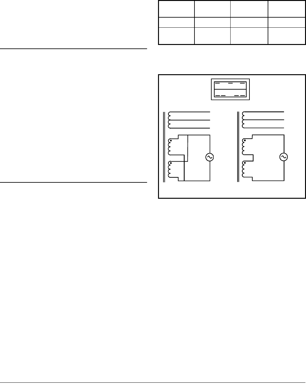
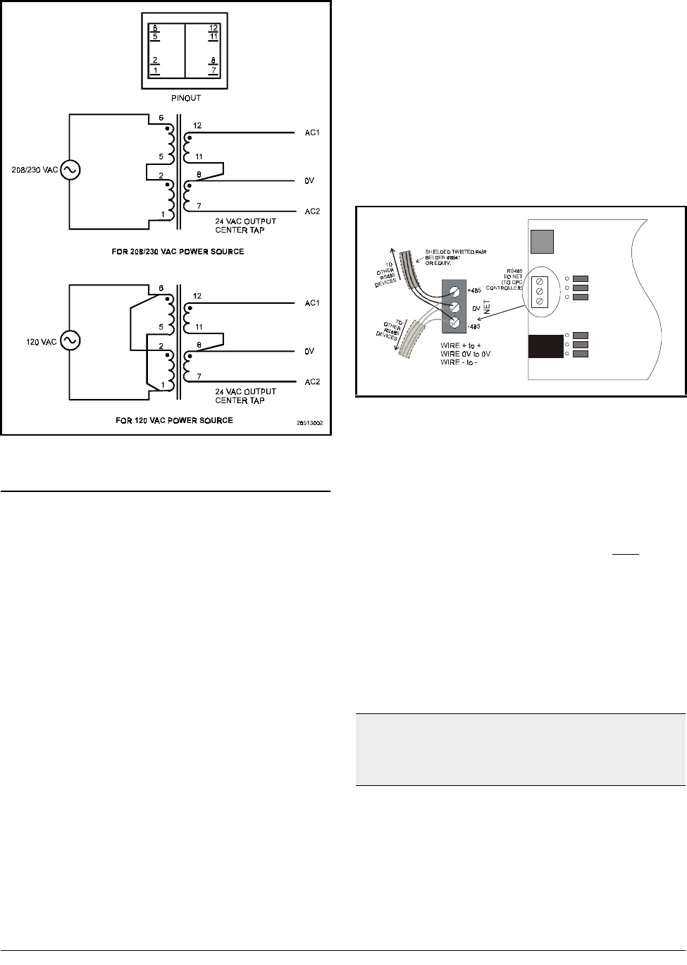
Figure 2-1 shows how to connect the 56VA
and 100VA transformers to the RF Gateway
power connector. Figure 2-2 shows how to con-
nect the 175VA transformer to the RF Gateway.
Three-
Board Six-Board Ten-
Board
P/N 640-0043 640-0045 640-0048
Power
Rating 56 VA 100 VA 175 VA
Table 2-1-Power Ratings for CPC Transformers
Figure 2-1 - Pinout for the 56VA (640-0043) and 100VA (640-
0045) Transformers
26513001
208 VAC
110 VAC
1
1
2
2
4
4
5
5
FOR 208 VAC POWER SOURCE
FOR 110 VAC POWER SOURCE
10
10
8
8
6
6
AC1
AC1
0V
0V
AC2
AC2
PINOUT
10 8 6
12 45
Wiring the RF Gateway to a CPC Site Controller (I/O Network) Installing the RF Gateway • 7
2.3. Wiring the RF Gateway to
a CPC Site Controller (I/O
Network)
Each Einstein or REFLECS site controller
that will receive a temperature value from an RF
Sensor must have an RF Gateway installed on its
RS485 I/O Network. For Einstein controllers,
this means the RF Gateway will be installed on
the I/O Network; for RMCC, BEC, BCU, and
other REFLECS products, the RF Gateway will
be installed on the COM A or COM D network.
2.3.1. Wire Connection
Using shielded three-conductor network
cable (Belden #8641 or equivalent), connect the
RS485 I/O Network wire to the three-terminal
connector on the RF Gateway board as shown in
Figure 2-3. For further information about how
RS485 networks are configured, refer to your
site controller’s user manual.
2.3.2. Setting the Board Number-
ing Dip Switch
The Einstein or REFLECS controller inter-
prets the RF Gateway board as a series of four
16AI Analog Input boards numbered in succes-
sion. Dip switches 1 through 4 set the first board
number used by the RF Gateway; when this
number is set, the RF Gateway will also use the
next three board numbers above the first board
number. For example, if an RF Gateway dip
switch is set to board number 3, the RF Gateway
will use board numbers 3, 4, 5, and 6 on the I/O
Network.
Figure 2-2 - Pinout for the 175VA (640-0048) Transformer
Figure 2-3 - Connecting the RF Gateway to the RS485 Network
Note: The RF Gateway dip switch is mounted upside
down on the circuit board. Figure 2-4 and Figure 2-5
show the correct positions of the dip switches when
viewed upside down.

8 • RF Sensor System I&O Manual 026-1702 Rev 0 10-30-00
2.3.3. Setting the Baud Rate Dip
Switch
Dip switches 6 and 7 control the baud rate at
which the RF Gateway communicates with the
site controller on the RS485 Network. These
switches must be set to the same baud rate set-
ting as the Einstein or REFLECS (usually 9600
baud).
Dip switch 8 controls the baud rate at which
the RF Gateway communicates with the other
devices on the Token Ring Network. This baud
rate may only be set to either 9600 baud (switch
DOWN) or 19600 baud (switch UP). All RF
Gateways and RF Receivers on the Token Ring
Network must have the same baud rate dip
switch setting. It is recommended you use 9600
baud as the Token Ring Network baud rate.
2.3.4. Setting the RS485 I/O Termi-
nation Jumpers
As part of an area controller’s RS485 I/O
(COM A or COM D) Network, an RF Gateway
must be terminated if it is the end device of a
daisy chain. Refer to the controller’s user man-
ual for information about daisy chain networks
and how they are terminated.
To terminate the RF Gateway, set the I/O
Network Jumpers to the LEFT position as shown
in Figure 2-6. To unterminate the RF Gateway,
set the jumpers to the RIGHT position.
Figure 2-4 - Dip Switch Setting for Numbering RF Gateway
Figure 2-5 - Dip Switch Setting for Numbering RF Gateway
Figure 2-6 - RF Gateway RS485 I/O Network Termination
Networking Gateways and Receivers (Token Ring Network) Installing the RF Gateway • 9
2.4. Networking Gateways
and Receivers (Token
Ring Network)
The RS485 Token Ring Network intercon-
nects all RF Gateways and Receivers on the site.
Like the RS485 I/O Networks that interconnect
the area controllers, input boards, output boards,
and RF Gateways, the Token Ring Network
must be set up in a daisy chain configuration.
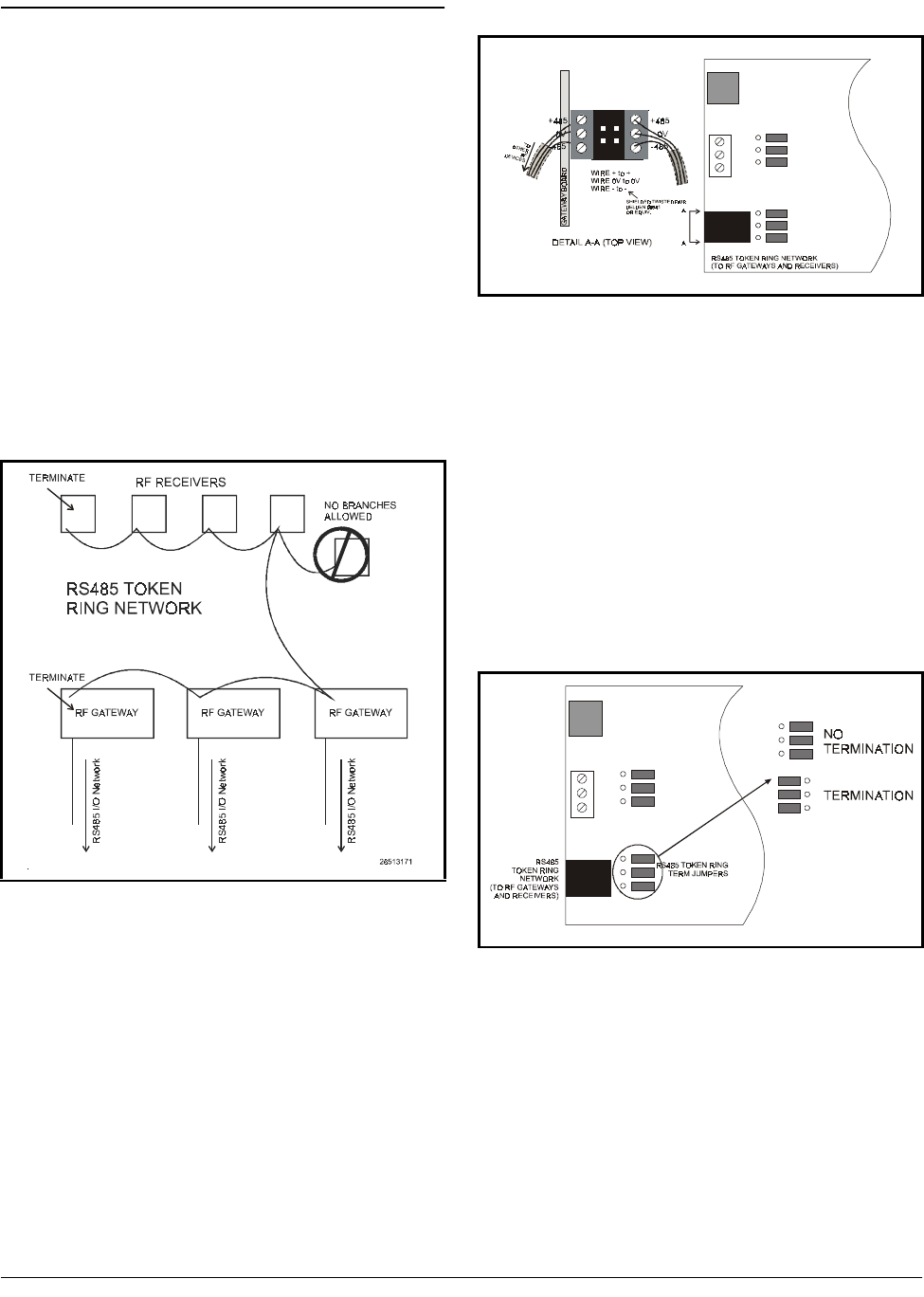
All devices must be wired together in a single
chain as shown in Figure 2-7, with no branches
and with no device connected to more than two
other devices.
2.4.1. Wiring the Token Ring Net-
work to the Gateway
Using shielded three-conductor cable
(Belden #8641 or equivalent), wire the RF Gate-
way to the Token Ring Network as shown in
Figure 2-8.
2.4.2. Setting the Token Ring Net-
work Termination Jumpers
As shown in Figure 2-7, the Token Ring
daisy chain must be terminated at the two
devices at the end of the chain. The location of
the termination jumpers on the RF Gateway are
shown in Figure 2-9. To terminate an RF Gate-
way, set the jumpers to the LEFT position. To
unterminate the RF Gateway, set the jumpers to
the RIGHT position.
Figure 2-7 - Daisy Chain Configuration - Token Ring Network
Figure 2-8 - Token Ring Network Wiring
Figure 2-9 - RS485 Token Ring Network Termination

10 • RF Sensor System I&O Manual 026-1702 Rev 0 10-30-00
3 Installing the RF Re-
ceiver
Installing an RF Receiver requires mounting
the receiver, powering the receiver, and network-
ing the receiver together with other receivers and
gateways on the RS485 Token Ring Network.
3.1. Mounting and Placement
of the RF Receiver
3.1.1. Environmental Operating
Conditions
The RF Receiver should be mounted in an
environment with ambient temperature between
30°F and 120°F, with a non-condensing relative
humidity between 5% and 95%.
3.1.2. Placement
The RF Receiver must be placed above the
sales floor within 150 feet of the sensors it will
receive transmissions from. Each RF Sensor in
the store must be no more than 150 feet from an
RF Receiver, so for installations that require
multiple receivers, make sure each RF Receiver
is placed so that all RF Sensors have a receiver
within the maximum distance.
3.1.3. Mounting
The receiver may be mounted either against
the ceiling (with the antenna pointing toward the
floor) or on top of a case (with the antenna point-
ing directly toward the ceiling). Alternately, the
receiver may be mounted sideways (e.g. on a
riser or a wall), but this will limit the range of
reception to only those RF Sensors that are
within the 180° arc of the direction the antenna
is pointing (i.e. it may not pick up sensors
located behind the receiver base).
Note the status LEDs and wire connections
are located on the bottom of the receiver enclo-
sure; try to mount the receiver so that these con-
nections are accessible.
3.2. Powering the RF Receiv-
er
The RF Receiver requires a 9VDC power
source. A 110VAC to 9VDC transformer is sup-
plied with the RF Receiver. Plug the adapter into
the receiver base, and connect the transformer to
a 110VAC line.
3.3. Wiring the RF Receiver to
a CPC Site Controller
Each RF Receiver passes along sensor val-
ues it receives to an RF Gateway on its RS485
Token Ring Network.

Wiring the RF Receiver to a CPC Site Controller Installing the RF Receiver • 11
3.3.1. Wire Connection
Connect the Token Ring Network wire to the
three-terminal connector on the RF Receiver
board as shown in Figure 3-1.
3.3.2. Setting the Token Ring Net-
work Termination Jumpers
The devices at each end of the Token Ring
Network daisy chain must be terminated. To ter-
minate the Token Ring Network at the RF
Receiver, set the jumpers to the UP position, as
shown in Figure 3-2. To unterminate the RF
Gateway, set the jumpers to the DOWN position.
3.3.3. Setting the Receiver Num-
bering Dip Switch
The RF Receiver must be identified with a
unique number on the RF Gateway network.
This allows RF Gateways to determine the
source of incoming temperature readings. RF
Receivers must be numbered sequentially, start-
ing with #1 and continuing to the maximum
number of receivers allowed (currently 6).
Figure 3-1 - Connecting the RF Receiver to the RS485 Network
Figure 3-2 - RF Receiver Token Ring Termination Settings

12 • RF Sensor System I&O Manual 026-1702 Rev 0 10-30-00
To assign an RF Receiver a number on the
RF Gateway network, set switches 1-5 to the
desired number. See Figure 3-3.
3.3.4. Setting the Baud Rate Dip
Switch
Dip switches 6 and 7 control the baud rate at
which the RF Receiver communicates with the
site controller on the Token Ring Network.
These switches should be set to the same posi-
tion as all other Token Ring Network devices so
they will communicate at the same baud rate. It
is recommended the baud rate be set at 9600
baud for all Token Ring devices.
Figure 3-3 - Dip Switch Setting for Numbering RF Receiver
Figure 3-4 - Dip Switch Setting for RF Receiver Baud Rate
Placement of RF Sensors Installing the RF Sensor • 13
4 Installing the RF Sen-
sor
This section details how to install the various
models of RF Sensors, including mounting and
placement, activation, and clean switch and
defrost termination wiring.
4.1. Placement of RF Sensors
Ideally, all RF Sensor models, including
product simulators, should be located some-
where within a refrigerated case where a clear
line of sight exists between itself and an RF
Receiver. In any case, the signal path between
the RF Sensor and the RF Receiver should
not be blocked by large amounts of product
or thick metal case walls.
4.1.1. RF (Short-Range) Ambient
Sensor
The RF Ambient Sensor kit includes a plas-
tic mounting clip. This clip may be fastened any-
where on a shelf or the side of a refrigerated
case. After mounting the clip, the sensor may be
snapped on to the mounting clip.
4.1.2. RF Long-Range Transmitter
The RF Long-Range Sensor transmitter
enclosure is equipped with two endcaps, each of
which has a mounting hole. Screw the sensor
enclosure to a shelf or the side of a case using
the endcap mounting holes.
4.1.3. RF Product Simulator
The RF Product Simulator kit includes a
plastic mounting clip. This clip may be fastened
anywhere on a shelf or the side of a refrigerated
case. After mounting the clip, the sensor may be
snapped on to the mounting clip.
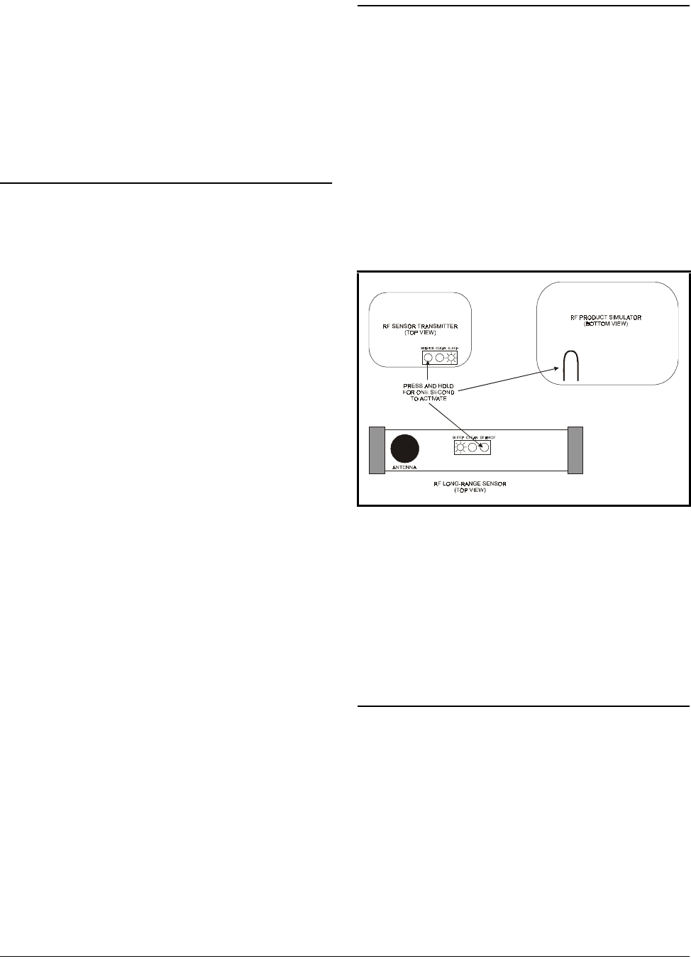
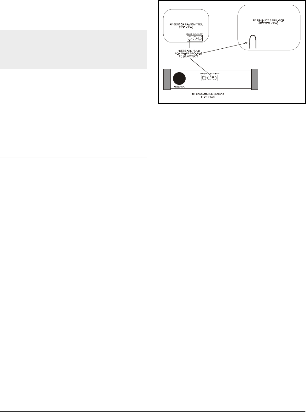
4.2. Activation
All RF Sensors will be shipped with the
power OFF (a.k.a. Sleep mode) to save battery
life. The sensors must be activated before they
will start transmitting. To activate the sensor,
locate the Service button and press for one sec-
ond (see Figure 4-1 for the service pin loca-
tions).
When activated, the sensor LED will stay
ON for one second to indicate the sensor is exit-
ing Sleep mode and beginning operation.
4.2.1. Verifying Active State
When an RF Sensor is active, you can verify
its active state by momentarily pressing the Ser-
vice button and then releasing. If active, the sta-
tus LED will flash once. If the light does not
come on, it is either in Sleep mode or has a dead
or missing battery.
4.3. Clean Switch and Defrost
Termination Wiring
Sensor models with internal clean switches
do not require any extra wiring to enable clean
switch functionality; the button on the sensor
enclosure acts as a clean switch.
Figure 4-1 - RF Sensor Activation

14 • RF Sensor System I&O Manual 026-1702 Rev 0 10-30-00
Sensor models with connections for external
clean switches and digital defrost termination
sensors are equipped with a two-wire pigtail.
Connect the clean switch or defrost termination
contacts to these leads.
WARNING! External clean switch and defrost ter-
mination inputs are to be connected to dry contacts
only. Do not connect the leads to any voltage or current
source. Doing so will damage the sensor and void the
warranty.

What is Commissioning? Commissioning the RF Sensors • 15
5 Commissioning the
RF Sensors
5.1. What is Commissioning?
Commissioning is the act of linking an RF
Sensor’s input to a virtual "board and point"
address in a specific RF Gateway’s memory so it
can be read and used by a CPC area controller.
The act of commissioning involves assigning
each virtual board and point in an RF Gateway’s
software with either the temperature value or the
digital input value from a specific RF Sensor.
This is achieved by:
• Specifying the unique ID number of the RF
Sensor that will supply the value to the cho-
sen board and point address, and
• Specifying whether the board and point
address will output the sensor’s temperature
value or the digital input value (from either
the clean switch or the defrost termination
sensor).
A sensor can be commissioned either by
manually entering sensor ID numbers into the
RF Gateway software or by pressing a sensor’s
service pin to broadcast the ID number to the RF
Gateway via an operational RF Receiver.
5.2. Manual Entry Method
Each RF Sensor and product simulator has a
sticker on the enclosure that displays an ID num-
ber unique to the sensor. This sticker also has a
perforated tag that may be removed from the
enclosure.
When using the Manual Entry method of
commissioning sensors, it is recommended you
remove each perforated ID tag after installation
and attach it to a data sheet along with informa-
tion about its location and the name of the Ein-
stein or REFLECS controller that will read the
sensor’s value. Appendix A provides a template
that may be photocopied for creating RF Sensor
data sheets.
When you’ve collected all the ID numbers
from the RF Sensors and product simulators for
your site, the ID numbers may be entered on the
RF Gateways to commission the sensors.
Figure 5-1 - The Process of Commissioning
16 • RF Sensor System I&O Manual 026-1702 Rev 0 10-30-00
5.2.1. Entering the ID Numbers on
the RF Gateway
The RF Gateway board is designed to simu-
late four 16AI Analog Input boards, each of
which has sixteen inputs, for a total of 64 inputs
per gateway. To commission a sensor, you must
use the Hand-Held Terminal to associate the sen-
sor ID number with a "board and point" input
address on the gateway.
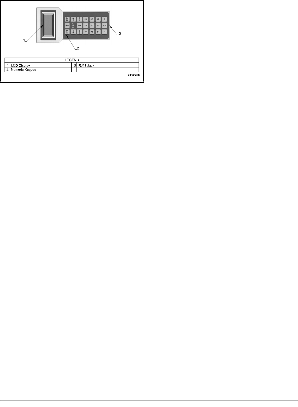
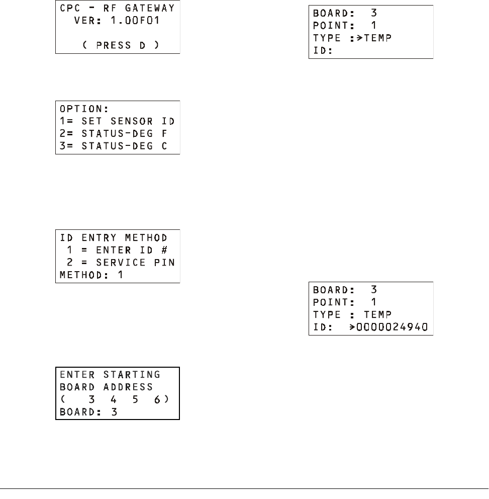
1. Plug the Hand-Held Terminal into the HHT
jack on the RF Gateway. The HHT should
power up and display the opening screen.
2. Press the DOWN ARROW key to display
the Options menu.
3. Press the RIGHT ARROW, 1, DOWN
ARROW, and DOWN ARROW to select
the "Set Sensor ID" option and navigate to
the ID Entry Method screen.
4. In the ID Entry Method screen, press
RIGHT ARROW, 1, DOWN ARROW,
and DOWN ARROW to select the "Enter
ID #" method and navigate to the Enter Start-
ing Board Address menu.
5. The Enter Starting Board Address menu
allows you to jump to Point 1 of the number
of the "board" you wish to configure. The
four board numbers reserved by this gateway
are shown in parenthesis on line 3 of the
screen. To begin commissioning sensors on a
"board," press RIGHT ARROW, the num-
ber of the board you wish to configure,
DOWN ARROW, and DOWN ARROW.
6. The commissioning screen for Point 1 of the
board number you chose will be visible on
the screen. There are two configurable
parameters on this screen: TYPE, and ID.
Press the RIGHT ARROW key to move the
cursor to the TYPE field.
7. If you want this board and point input to be
the temperature read by the RF Sensor, press
1 to change the TYPE field to "TEMP." If
you want this board and point input to be the
state of the RF Sensor’s digital output
(whether it be its clean switch or defrost ter-
mination sensor input), press 2 to change the
TYPE field to "DIGITAL." When selected,
press the DOWN ARROW key to confirm.
8. The cursor should now be on the ID field. In
the ID field, enter the number from the ID
tag or sticker on the RF Sensor enclosure.
When finished, press the DOWN ARROW
key to confirm and save.
9. Press the DOWN ARROW key again to
move on to the next point on the board. Fol-
low steps 6 through 8 again to commission
the next board point. If you wish to switch to
a different board, pressing F2 will move you

Service Pin Method Commissioning the RF Sensors • 17
back to the Enter Starting Board screen
described in step 4.
5.3. Service Pin Method
All RF Sensor models have a service pin
that, when pressed, will transmit its ID number.
The service pin can be used to commission the
sensor by commanding the RF Gateway to
receive the transmitted ID number and assign it
to a "board and point" input address.
This process will likely require two people:
one to set the RF Gateway up to receive the sen-
sor ID transmissions, and one on the sales floor
to press the service pins.
5.3.1. Setting up the RF Gateway to
Receive ID Transmissions
The RF Gateway board is designed to simu-
late four 16AI Analog Input boards, each of
which has sixteen inputs, for a total of 64 inputs
per gateway. To commission a sensor, you must
use the Hand-Held Terminal to associate the sen-
sor ID number with a "board and point" input ad-
dress on the gateway.
1. Plug the Hand-Held Terminal into the HHT
jack on the RF Gateway. The HHT should
power up and display the opening screen.
2. Press the DOWN ARROW key to display
the Options menu.
3. Press the RIGHT ARROW, 1, DOWN
ARROW, and DOWN ARROW to select
the "Set Sensor ID" option and navigate to
the ID Entry Method screen.
4. In the ID Entry Method screen, press
RIGHT ARROW, 2, DOWN ARROW,
and DOWN ARROW to select the "Service
Pin" method and navigate to the Enter Start-
ing Board Address menu.
5. The Enter Starting Board Address menu
allows you to jump to Point 1 of the number
of the "board" you wish to configure. The
four board numbers reserved by this gateway
are shown in parenthesis on line 3 of the
screen. To begin commissioning sensors on a
"board," press RIGHT ARROW, the num-
ber of the board you wish to configure,
DOWN ARROW, and DOWN ARROW.
6. The commissioning screen for Point 1 of the
board number you chose will be visible on
the screen. There are two configurable
parameters on this screen: TYPE, and ID.
Press the RIGHT ARROW key to move the
cursor to the TYPE field.
NOTE: For simplicity, it is recommended you com-
mission a sensor’s digital input value on the point im-
mediately after its temperature value. For example, if
Sensor A’s temperature value is commissioned as
Board 1, Point 1, commission its digital input value as
Board 1, Point 2.
WARNING! Make sure no one else on site is com-
missioning or activating sensors while you are commis-
sioning sensors. Otherwise, the RF Gateway may read
a service button transmission from the wrong RF Sen-
sor and commission improperly.
18 • RF Sensor System I&O Manual 026-1702 Rev 0 10-30-00
7. If you want this board and point input to be
the temperature read by the RF Sensor, press
1 to change the TYPE field to "TEMP." If
you want this board and point input to be the
state of the RF Sensor’s digital output (either
its clean switch or defrost termination sensor
input), press 2 to change the TYPE field to
"DIGITAL." When selected, press the
DOWN ARROW key to confirm.
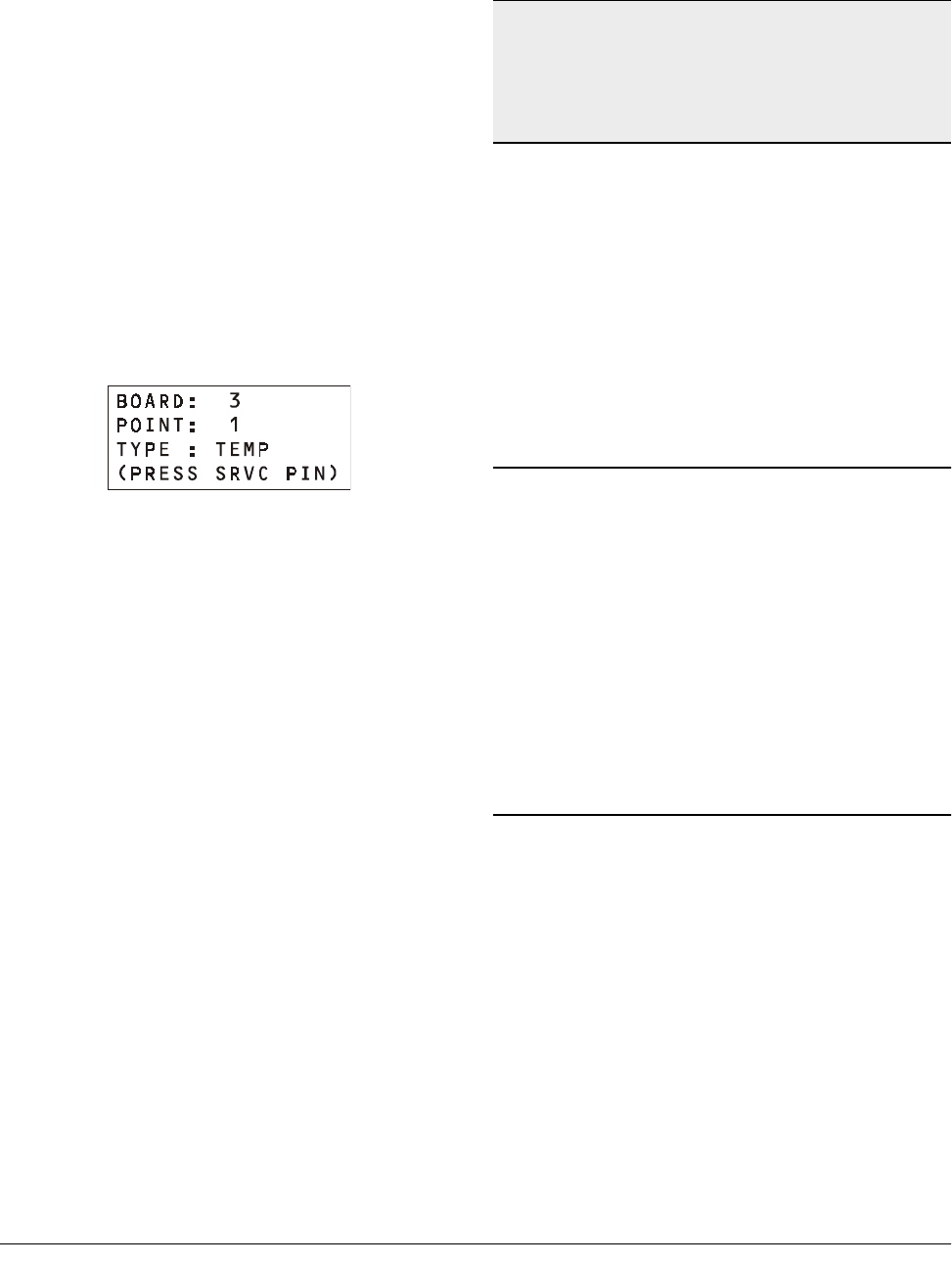
8. The cursor should now disappear, and line 4
of the display will read "(PRESS SRVC
PIN)." Press and hold the Service button on
the RF Sensor for one second and then
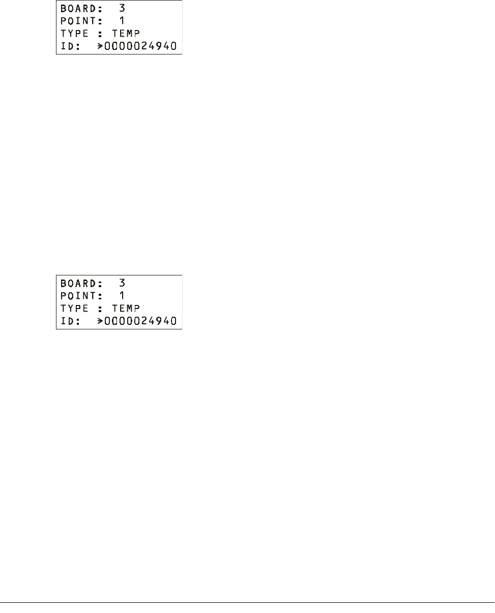
release. The RF Gateway should receive the
Service button message and fill the ID field
in with the ID number of the RF sensor.
The RF Gateway will wait one minute to
receive the Service button signal. If it is not
received, the message "SRVC PIN TIMEOUT"
will appear (you may also manually cancel the
wait time by pressing CANCEL.)
If commissioning was unsuccessful, press
the UP ARROW key and repeat steps 7 and 8.
If the sensor will still not commission, refer to
Appendix B for troubleshooting information, or
attempt to commission the sensor using the
Manual Entry method (Section 5.2.).
9. Press the DOWN ARROW key again to
move on to the next point on the board. Fol-
low steps 6 through 8 again to commission
the next board point. If you wish to switch to
a different board, pressing F2 will move you
back to the Enter Starting Board screen
described in step 4.
5.3.2. Hand-Held Terminal Screen
Navigation Tips
• At any time, pressing F1 on the HHT will move you
back to the opening screen.
• Any time you are entering data in a field where the
arrow cursor is visible, pressing CANCEL will
clear the field. During commissioning, pressing
CANCEL with the cursor in an ID field will delete
a sensor from the RF Gateway’s memory (see Sec-
tion 5.5., Decommissioning a Sensor from the RF
Gateway).
5.4. Verifying Successful
Commissioning
Immediately after being commissioned, the
RF Gateway will begin grabbing sensor trans-
missions from its associated RF Sensors. You
may verify that all RF Sensors you have com-
missioned for this gateway are communicating
properly by viewing their status using the Hand-
Held Terminal. Refer to Section 7.4. for instruc-
tions on how to do this.
5.5. Decommissioning a Sen-
sor from the RF Gateway
RF Sensor records may be deleted or
"decommissioned" from the RF Gateway’s
memory. The process of decommissioning a sen-
sor is similar to commissioning, except instead
of entering ID numbers, you must delete them.
5.5.1. Decommissioning Manually
NOTE: For simplicity, it is recommended you com-
mission a sensor’s digital input value on the point im-
mediately after its temperature value. For example, if
Sensor A’s temperature value is commissioned as
Board 1, Point 1, commission its digital input value as
Board 1, Point 2.
Decommissioning a Sensor from the RF Gateway Commissioning the RF Sensors • 19
Entered ID Numbers
If you commissioned the sensors using the
Manual Entry method, follow the instructions in
Section 5.2. to navigate to the commissioning
screen of the sensor input you wish to delete.
Press the RIGHT ARROW key twice until
the arrow cursor points to the ID number entered
for the sensor. Press CANCEL to erase this
number. The sensor input is now decommis-
sioned. If this sensor has both a temperature and
a digital value input commissioned, repeat this
process for the second input.
5.5.2. Decommissioning ID Num-
bers Entered By Service Pin
If you commissioned the sensors using the
Service Button method, follow the instructions
in Section 5.3. to navigate to the commissioning
screen of the sensor input you wish to delete.
Press the RIGHT ARROW key twice until
the arrow cursor points to the ID number entered
for the sensor. Press CANCEL. This will both
erase this number and cause the RF Gateway to
prompt you to press the service button. If you
wish to commission a different input to this
board and point, you may press the service pin of
the new sensor now to commission it. Other-
wise, if you wish to leave this board and point
empty, press CANCEL again to end the wait
time.
If this sensor has both a temperature and a
digital value input commissioned, repeat this
process for the second input.

20 • RF Sensor System I&O Manual 026-1702 Rev 0 10-30-00
6 Connecting Sensors
to Einstein/REFLECS
The commissioning process described in
Section 5 assigns each sensor a virtual "board
and point" address in an RF Gateway’s memory.
Once a sensor is commissioned, the controller on
the RF Gateway’s RS485 I/O Network treats the
RF Gateway in all respects as a series of four
16AI Analog Input Boards numbered in succes-
sion.
Programming Einstein and REFLECS appli-
cations to use RF Sensor values is exactly the
same process as programming Einstein and
REFLECS applications to use conventional tem-
perature sensors connected to 16AI input points;
just enter the virtual board and point address of
the RF Sensor in the input definition fields.
Refer to your site controller’s user manual
for information about setting up board and point
addresses for inputs in Einstein and REFLECS
applications.
Status LEDs Operation and Maintenance of the RF Sensor System • 21
7 Operation and Mainte-
nance of the RF Sen-
sor System
7.1. Status LEDs
7.1.1. RF Sensors
All RF Sensor models have a single LED on
top of the enclosure. This LED will flash once ev-
ery three seconds to indicate the sensor is operat-
ing in Clean mode. Aside from Clean mode, there
are only three events that will cause the LED to
be ON.
1. The LED will be ON for one second when
you activate the sensor (see Section 4.2., Ac-
tivation).
2. The LED will flash twice when you switch
the sensor into Sleep mode (see Section 7.5.,
RF Sensor Sleep Mode).
3. The LED will flash once each time you press
the Service Button while the sensor is in Ac-
tive mode. This indicates the sensor is not in
Sleep mode.
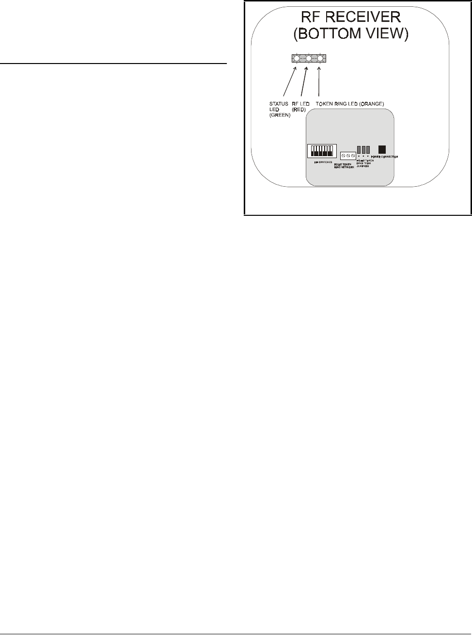
7.1.2. RF Receivers
The RF Receiver has three LED indicators:
the STATUS LED, the RF LED, and the TOKEN
RING LED.
7.1.2.1. The Status LED
The STATUS LED flashes GREEN once per
second to indicate the receiver is ON. If this light
does not flash, the receiver is unpowered.
7.1.2.2. The RF LED
The RF LED flashes RED every time it
receives a transmission from an RF Sensor. In a
properly working system, this light should flash
occasionally several times over the course of 3-5
minutes. If after five minutes the LED does not
flash at all, there may be a problem with the
receiver.
7.1.2.3. The Token Ring LED
The TOKEN RING LED flashes ORANGE
when it sends transmission data to the RF Gate-
ways. The rate at which this light turns ON
depends on the number of receivers on site,
because RF Receivers take turns sending col-
lected data to the gateways. In a properly work-
Figure 7-1 - RF Receiver LED Locations

22 • RF Sensor System I&O Manual 026-1702 Rev 0 10-30-00
ing system, if this light does not come on at all
for one minute, there may be a problem with
either the RF Receiver or the Token Ring Net-
work.
7.1.3. RF Gateway
The RF Gateway has four LEDs: a General
Status LED, an ALARM LED, an RS485 I/O
NET STATUS LED, and a TOKEN RING STA-
TUS LED (Figure 7-2).
7.1.3.1. The General Status LED
The General Status LED light flashes
GREEN once every second to indicate it is pow-
ered up.
7.1.3.2. The Alarm LED
The Alarm LED (red) indicates when an
alarm condition exists for the RF Gateway.
There are five possible LED states, each of
which indicates a different condition.
• OFF - No alarm conditions are active, and the RF
Gateway is functioning normally.
• Flashes 4 times/second - There is a problem with
the physical hardware (ROM) of the RF Gateway
board. The board may need to be replaced.
• Flashes 2 times/second - There is no user configu-
ration on this RF Gateway - no sensors are commis-
sioned in its memory, and it is essentially in an
empty state. This LED state will occur when the
board is first powered up on-site.
• Flashes 1 time/second - The RF Gateway is not
communicating with the area controller due to a pos-
sible RS485 I/O Network or controller failure.
• ON with no flashing - The RF Gateway is not de-
tecting any traffic on the Token Ring Network.
Check Token Ring Network connections.
7.1.3.3. RS485 I/O Network Status LED
The RS485 I/O Network Status LED flashes
ORANGE to indicate traffic on the I/O Network.
If this light does not come on at all and the
ALARM LED is flashing once per second, there
is a problem with the RS485 I/O Network or the
area controller.
7.1.3.4. Token Ring Network Status
LED
The Token Ring Network Status LED will
flash ORANGE briefly every time a message is
passed across the Token Ring Network. How-
ever, when the RF Gateway receives a message
that it detects as a message from one of its com-
missioned sensors, the LED will flash brightly
for 1/2 second.
If the RF Gateway has commissioned sen-
sors and is communicating properly, you should
see this LED flash brightly several times within
the course of a few minutes.
7.2. Clean Switch Operation
The clean switch input on the RF Sensors
allows you to manually suspend all temperature
alarming on the case so that the case may be
cleaned or serviced.
Activating Clean mode for an RF Sensor or
product simulator is slightly different depending
on whether the clean switch contacts are internal
(i.e. activated by pressing the Clean button on
the enclosure) or external.
Figure 7-2 - RF Gateway LED Locations

Battery Life and Replacement Operation and Maintenance of the RF Sensor System • 23
7.2.1. Internal Clean Switch
For sensor models equipped with "Clean"
buttons, press and hold the Clean button for 3
seconds to switch the sensor from Normal mode
to Clean mode. After 3 seconds, the sensor LED
should start flashing to indicate Clean mode is
active.
While the sensor is in Clean mode, pressing
and holding the Clean button again for 3 seconds
will switch the sensor back into Normal mode.
The LED should no longer flash when the sensor
has successfully switched to Normal mode.
7.2.2. External Clean Switch
An externally wired clean switch may be
either a push button or a static switch. If the
clean switch is a push button, press and hold the
button for 3 seconds to switch from Normal to
Clean mode. To switch from Clean mode back to
Normal mode, press and hold the button for 3
seconds.
If the clean switch is a static switch, the sen-
sor will go into Clean mode when the switch is
in the CLOSED position for longer than 3 sec-
onds. Clean mode will end when the switch is
returned to the OPEN position.
Like the internal clean switch, the sensor’s
LED will flash once per three seconds when in
Clean mode.
7.3. Battery Life and Replace-
ment
The battery life of an RF Sensor depends on
the frequency of transmission. Sensors config-
ured to transmit once every three minutes (the
factory default) will have a battery life of seven
years, while sensors configured to transmit once
every 40 seconds will have a battery life of three
years.
Batteries may be replaced by opening the
sensor enclosure, removing the battery from the
circuit board, and replacing it with a new battery.
The battery is a special low-temperature battery
available from CPC (P/N 119-5101) — DO NOT
USE ANY OTHER REPLACEMENT BATTERY.
7.3.1. Reactivating the RF Sensor
After removing and replacing the battery, the
sensor will revert back to Sleep mode and will
need to be reactivated. Refer to Section 4.2.,
Activation, for information about how to acti-
vate an RF Sensor.
7.4. Viewing Status Using the
Hand-Held Terminal
For troubleshooting purposes, the RF Gate-
way allows you to view the temperature and dig-
ital input values of all commissioned RF Sensors
with the Hand-Held Terminal.
1. Plug the Hand-Held Terminal into the HHT
jack on the RF Gateway. The HHT should
power up and display the opening screen.
2. Press the DOWN ARROW key to display
the Options menu.
3. Press the RIGHT ARROW, and press 2 to
view temperatures in degrees Fahrenheit or 3
to view temperature in degrees Celsius. Press
DOWN ARROW twice to navigate to the
Enter Starting Board Address screen.

24 • RF Sensor System I&O Manual 026-1702 Rev 0 10-30-00
4. The Enter Starting Board Address menu
allows you to jump to Point 1 of the number
of the "board" you wish to look at. The four
board numbers reserved by this gateway are
shown in parenthesis on line 3 of the screen.
To view status of sensors on a "board," press
RIGHT ARROW, the number of the board
you wish to configure, DOWN ARROW,
and DOWN ARROW.
5. Point 1 of the board you selected in step 4
should be visible. This screen will display
the type of input this point is configured as,
and the last recorded value of the sensor.
Use the UP ARROW and DOWN
ARROW keys to scroll through all 64 "board
and point" addresses on the RF Gateway.
If a point’s value shows the message "NO
UPDATE," this means the RF Gateway has not
received a transmission from the RF Sensor for
at least several minutes. Refer to Appendix B for
troubleshooting information.
If a point’s value shows the message "NOT
CFG," this means the point you are viewing was
never configured or commissioned and is essen-
tially “empty.” If this point is supposed to be
commissioned, follow the instructions in Sec-
tion 6 to commission the point.
7.4.1. Viewing Update Counts
In addition to viewing the current values of
all RF sensors and inputs with the HHT, you
may also view how many sensor value updates
the RF Gateway has received for a sensor. This
will allow you to troubleshoot an RF Sensor by
analyzing its performance over a period of time.
To make the HHT show sensor value
updates, locate switch #5 on the RF Gateway dip
switch, and set this switch to the ON position
(Figure 7-3). The HHT will now show sensor
update counts instead of temperature or digital
input values on the status screens. Follow the
instructions given in Section 7.4., Viewing Sta-
tus Using the Hand-Held Terminal, to view
update counts for each sensor.
TIP: While viewing the status of points, if you wish
to switch to viewing points on a different board, press
F2 to navigate directly to the Enter Starting Board
screen.
Figure 7-3 - Show Updates Dip Switch on RF Gateway
RF Sensor Sleep Mode Operation and Maintenance of the RF Sensor System • 25
The number in the VALUE field is the num-
ber of updates the RF Gateway has received
from the commissioned sensor since the last
time the sensor’s count was reset to zero.
7.4.1.1. Resetting the Sensor Update
Count
The update count for a sensor can be reset in
two ways. To clear an individual input’s count,
navigate to the input’s HHT status screen and
press CANCEL. The VALUE field should reset
to zero. A power loss to the RF Gateway will
reset all update counts back to zero.
7.5. RF Sensor Sleep Mode
Each RF Sensor is shipped from the factory
in a deactivated state called Sleep mode. During
Sleep mode, the sensor will not broadcast or do
anything that will drain the battery.
Section 4.2. explains how to activate a sen-
sor that is in Sleep mode. To return an active
sensor to Sleep mode, press and hold the Service
button on the sensor enclosure for ten seconds.
The sensor’s LED will flash twice to indicate the
sensor has entered Sleep mode.
NOTE: The Show Updates switch does not affect the
values being sent from the RF Gateway to the site con-
troller. The RF Gateway will only send temperature val-
ues and digital input values to the site controller, not
update count values.
Figure 7-4 - Putting a Sensor in Sleep Mode

Appendix A: RF Sensor Commissioning Data Sheets
Site Controller
Name Standard Circuit
Name Sensor ID
Sticker Number Physical Location
(Description) Board # Point # Temp or
Digital?
EXAMPLE EIN-
STEIN EXAMPLE CASE
#1 1st cheese case against west
wall 31TEMP
EXAMPLE EIN-
STEIN EXAMPLE CASE
#1 1st cheese case against west
wall 3 2 CLN
SWTCH
21943
21943

Site Controller
Name Standard Circuit
Name Sensor ID
Sticker Number Physical Location
(Description) Board # Point # Temp or
Digital?

Site Controller
Name Standard Circuit
Name Sensor ID
Sticker Number Physical Location
(Description) Board # Point # Temp or
Digital?

Site Controller
Name Standard Circuit
Name Sensor ID
Sticker Number Physical Location
(Description) Board # Point # Temp or
Digital?