Computime AAHZT11 thermostats User Manual
Computime Ltd. thermostats
User manual

Installation Manual
Orion EMS

September
1
3
, 20
12
Page
2
of
50
66 8003 00
2
-
8
Copyrights
The information in this document is subject to change at the sole discretion of VingCard Elsafe AS without notice.
Any use, operation or repair in contravention of this document is at your own risk. VingCard Elsafe AS does
not assume any responsibility for incidental or consequential damages arising from the use of this manual.
All information and drawings in this document are the property of VingCard Elsafe AS. Unauthorized use
and reproduction is prohibited.
VingCard is a registered trademark of VingCard Elsafe AS.

September
1
3
, 20
12
Page
3
of
50
66 8003 00
2
-
8
Table of contents
1.
G
ENERAL
........................................................................................................................................................... 4
2.
S
OFTWARE INSTALLATION
................................................................................................................................. 5
2.2 Installing an Orion EMS client ..................................................................................................................... 5
2.2.1 Starting an Orion EMS client................................................................................................................. 5
3.
C
OMPONENT INFORMATION
................................................................................................................................ 6
3.1 Thermostat controller................................................................................................................................... 6
3.1.1 Thermostat controller dimensions.......................................................................................................... 6
3.2 Thermostat................................................................................................................................................... 7
3.2.1 Thermostat buttons................................................................................................................................ 7
3.2.2 Thermostat display................................................................................................................................ 8
3.2.3 Thermostat dimensions.......................................................................................................................... 9
3.3 Parameters / specifications ......................................................................................................................... 10
3.4 Motion sensor ............................................................................................................................................ 12
3.4.1 Motion sensor dimensions ................................................................................................................... 13
3.4.2 Motion sensor specifications................................................................................................................ 13
4.
D
EVICE INSTALLATION AND COMMISSIONING
................................................................................................... 16
4.1 Inputs / outputs .......................................................................................................................................... 16
4.1.1 RS-485 interface.................................................................................................................................. 17
4.1.2 Configuration with thermostat controller ............................................................................................. 18
4.1.3 Configuration without thermostat controller......................................................................................... 19
4.2 Installing a thermostat controller ................................................................................................................ 20
4.2.1 Mounting a thermostat controller......................................................................................................... 20
4.3 Installing a thermostat................................................................................................................................ 21
4.3.1 Mounting a thermostat......................................................................................................................... 21
4.3.1.1 Thermostat placement................................................................................................................... 22
4.3.1.2 Thermostat battery exchange......................................................................................................... 22
4.3.2 Wiring a thermostat............................................................................................................................. 22
4.3.2.1 Recommended wire specification.................................................................................................. 22
4.3.2.2 Connecting a thermostat................................................................................................................ 22
4.3.2.3 Line to low voltage conversion ..................................................................................................... 23
4.3.2.4 Connecting a wired door switch.................................................................................................... 23
4.4 Installing a motion sensor........................................................................................................................... 24
4.4.1 Motion sensor placement..................................................................................................................... 25
4.5 Commissioning the system......................................................................................................................... 26
4.5.1 Commissioning when thermostat controller is used.............................................................................. 26
4.5.1.1 Joining the thermostat controller to the network ............................................................................ 26
4.5.1.2 Joining the in-room devices to the thermostat controller................................................................ 27
4.5.2 Commissioning when thermostat controller is not used........................................................................ 28
4.5.2.1 Joining the thermostat to the network............................................................................................ 28
4.5.2.2 Joining the in-room devices to the thermostat................................................................................ 29
4.6 Testing the in-room devices ....................................................................................................................... 31
A
PPENDIX
A:
O
RION
S
ERVICE CONNECTIONS
....................................................................................................... 32
A
PPENDIX
B:
F
IRMWARE UPGRADE
...................................................................................................................... 36
A
PPENDIX
C:
C
ONFIGURATION IN OFFLINE SCENARIOS
......................................................................................... 40
R
EVISION HISTORY
.............................................................................................................................................. 49

September
1
3
, 20
12
Page
4
of
50
66 8003 00
2
-
8
1. General
This manual
• describes how to install the Orion EMS (Energy Management System) option and if applicable
an Orion EMS client; chapter 2
- for the Orion EMS features to be shown in the VISIONLINE software, it is necessary to
install the Orion EMS option; follow the steps in section 2.1
- if the Orion EMS features should also be available in a separate client where the operators
do not see the “ordinary” VISIONLINE items such as doors, follow the steps in section 2.2;
this requires that the Orion EMS option has been installed in the VISIONLINE software
• gives information about the Orion EMS devices and parameters; chapter 3
• describes how to install and commission the Orion EMS devices; chapter 4
Note:
For daily operations when the system is in use, see Daily use manual Orion EMS. In that document,
more information about Orion Service and SysMon (System Monitor) features is also found.
The items used together with Orion EMS are:
• digital thermostat
Note:
Depending on installation conditions, also a thermostat controller is used or not. If used,
the thermostat controller is the master of the system and the thermostat is only a guest interface
device which transmits information to the thermostat controller for processing and decision making.
• motion sensor
• door monitoring device; lock, switch
• gateway (the same as is used for online doors; requires the Online option which is also installed
according to 2.1)
Note:
The gateway is not used in offline scenarios; see Appendix C for details.
Note:
For each room number, it is possible to have either
•
one wired thermostat
•
up to five motion sensors
•
up to five door switches
OR
•
one thermostat controller
•
up to five battery thermostats
•
up to five motion sensors
•
up to five door switches
Note:
The best conditions for Orion EMS are obtained if also the locks are online and commissioned to the
same ZigBee network as the thermostat and the motion sensor.
Note:
In the rest of this document, the term ‘thermostat’ includes thermostat as well as thermostat controller,
unless something else is stated.
September
1
3
, 20
12
Page
5
of
50
66 8003 00
2
-
8
2. Software installation
2.1 Installing an option
If the Orion EMS option (and Online option) has been ordered together with the VISIONLINE software, it is
included in the license code and will be set in the software when the license code is entered.
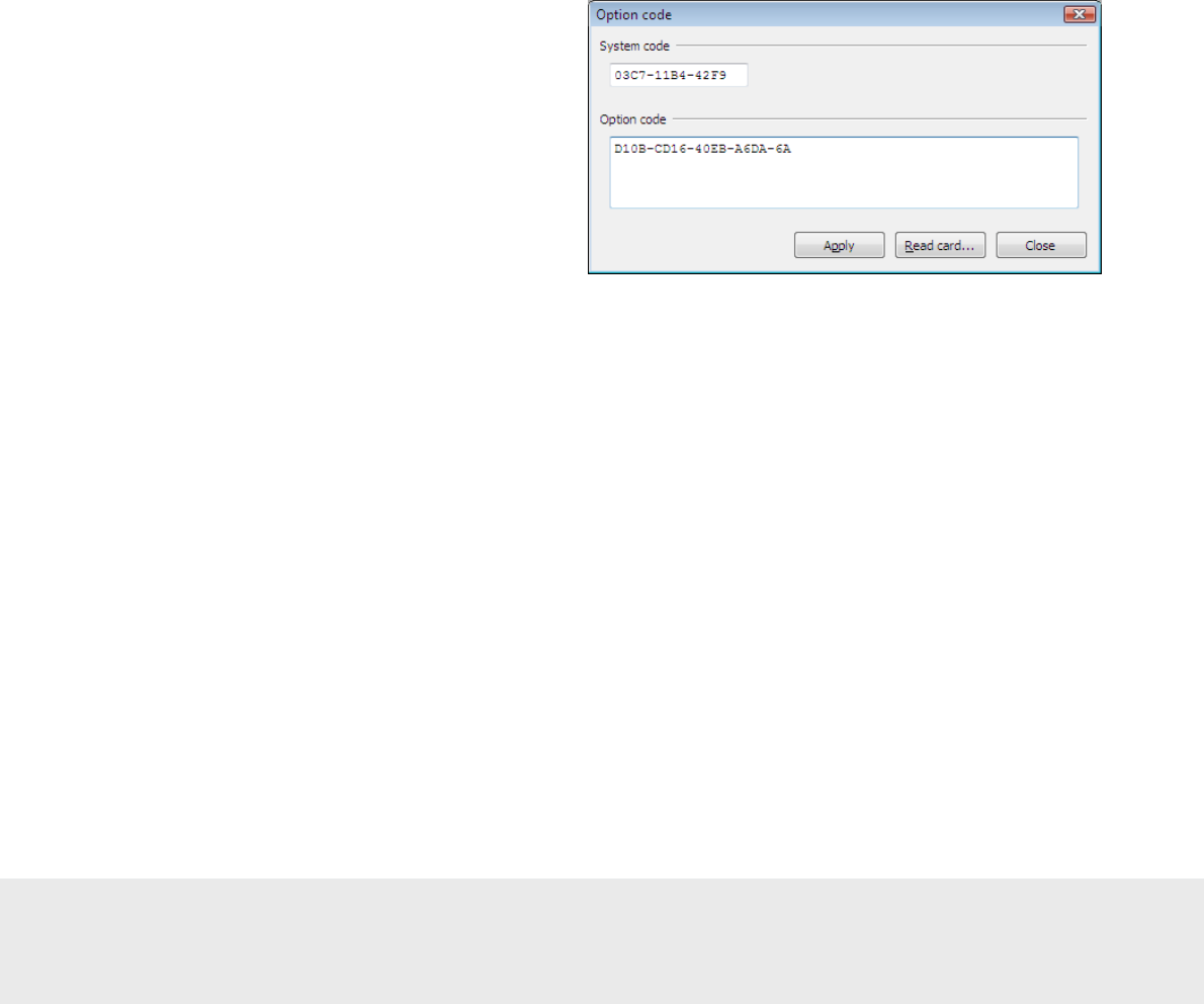
If the option(s) should be added to the system at a later occasion, when the license code has already been entered
and system ID is therefore set, an option code is used instead. Several software options can be included in one
option code. An operator with the authority to handle option codes must be logged on. Normally, options are
set by the system manager or the distributor.
When ordering the option, the system code must be communicated to the ordering department:
1. Double click on
System settings
under the
Reports
tab in the navigation window of VISIONLINE.
System settings
is available even if you are not logged on.
2. Communicate your system code to the order department; see order acknowledgement for phone number
and e-mail address. The system code can also be entered in the Ordering web page when making the order.
To install an option:
1. Go to
Tools/Option code
in VISIONLINE.
2. Enter the option code and click
Apply
.
2.2 Installing an Orion EMS client
If there should be a separate Orion EMS client (see chapter 1 for more information), this is installed according to
the ReadMe file for the applicable operating system. The ReadMe files are found on the Orion EMS software CD.
2.2.1 Starting an Orion EMS client
1. Click the
Start
button and go to
Programs/Orion EMS/Orion EMS
.
2. When requested, log on with the same user ID and password as for VISIONLINE.
September
1
3
, 20
12
Page
6
of
50
66 8003 00
2
-
8
3. Component information
As mentioned in chapter 1 General, two different thermostat configurations are available:
• battery operated thermostat that communicates via ZigBee to a wired thermostat controller
• wired thermostat and no thermostat controller
3.1 Thermostat controller
If the configuration with thermostat controller is used, the thermostat controller is the master of the in-room system.
This item has a built-in router via which it communicates with the VISIONLINE software (or Orion EMS software, if
applicable) and the devices within the room. It is also possible to have an offline scenario where there is no connection
to the server, and where each room can be seen as a PAN (personal area network) which is controlled by its thermostat
controller. In this case, the thermostat controller has a coordinator firmware instead of a router firmware.
Note:
The thermostat controller may not be sealed into a metal box.
When the different room devices are commissioned (see section 4.5.1.2 for details), they are joined to the router of
the thermostat controller and registered in the thermostat controller.
The thermostat controller stores all parameters needed for the energy management, with a few exceptions which are
stored in the thermostat; see section 3.3 for details. These are transferred either from a service device, or online from
the VISIONLINE/Orion EMS software.
The thermostat controller receives entry and exit information from the door lock or switch as well as information
from the motion sensor. This information is used to determine the occupancy status of the room and implement
energy savings strategy based on this information.
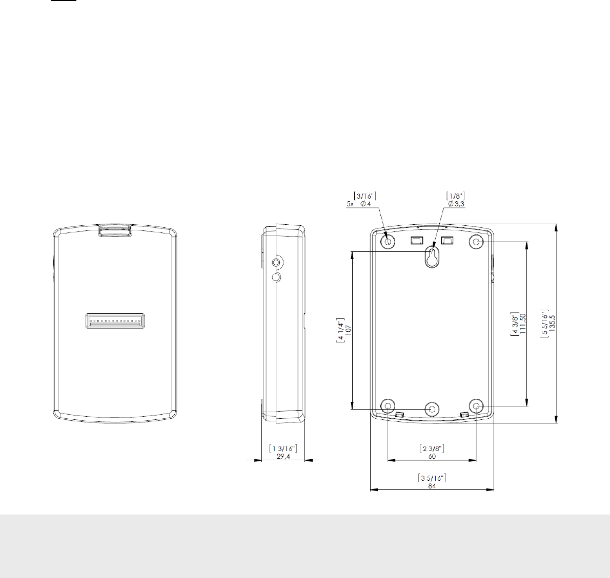
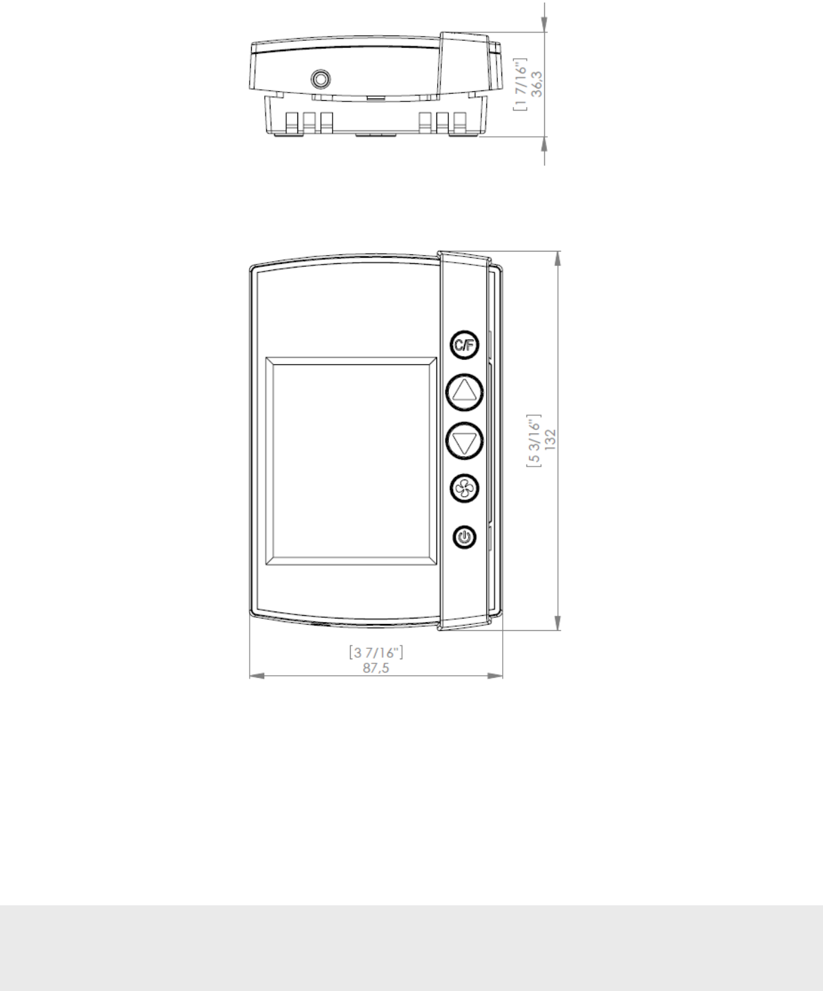
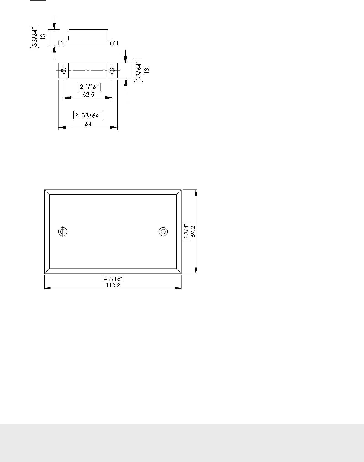
3.1.1 Thermostat controller dimensions
Dimensions in mm (inches)
Figure
1
September
1
3
, 20
12
Page
7
of
50
66 8003 00
2
-
8
3.2 Thermostat
The guest operates the thermostat, which depending on configuration communicates either
• with the thermostat controller
OR
• directly with the VISIONLINE software/Orion EMS software and the devices within the room.
The thermostat buttons and thermostat display are the same in both cases. In the case of battery operated
thermostat, 3AA batteries (4.5 VDC) in a battery package are used.
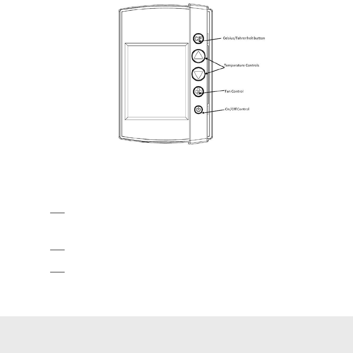
3.2.1 Thermostat buttons
The hotel guest controls the thermostat using the five buttons shown on the right side of the unit in Figure 2.
•
C/F:
Controls the temperature display. Pressing this button will toggle the temperature display between
Celsius and Fahrenheit.
•
Up and Down Arrows:
The up and down arrows are used to set the desired temperature. The thermostat
will automatically choose between heat and cool so there is no need for the guest to select the function.
Note:
Some systems are unable to switch between the heating and cooling functions. This does not change
the way the guest uses the system, but the thermostat is programmed accordingly and will not call for a
function that is not available.
•
Fan Control Button:
The Fan control button allows the user to select from up to three fan speeds or
choose ‘Automatic’ to let the thermostat determine the appropriate fan setting.
Note:
The ability to control fan speeds depends on the capability of the air handler as some systems
do not have three fan speeds.
•
On/Off Button:
The On/Off button toggles the thermostat power on or off.
Note:
Even when the unit is turned off, the energy management logic will take over when the room is
unoccupied to manage the temperature accordingly.
Figure
2
September
1
3
, 20
12
Page
8
of
50
66 8003 00
2
-
8
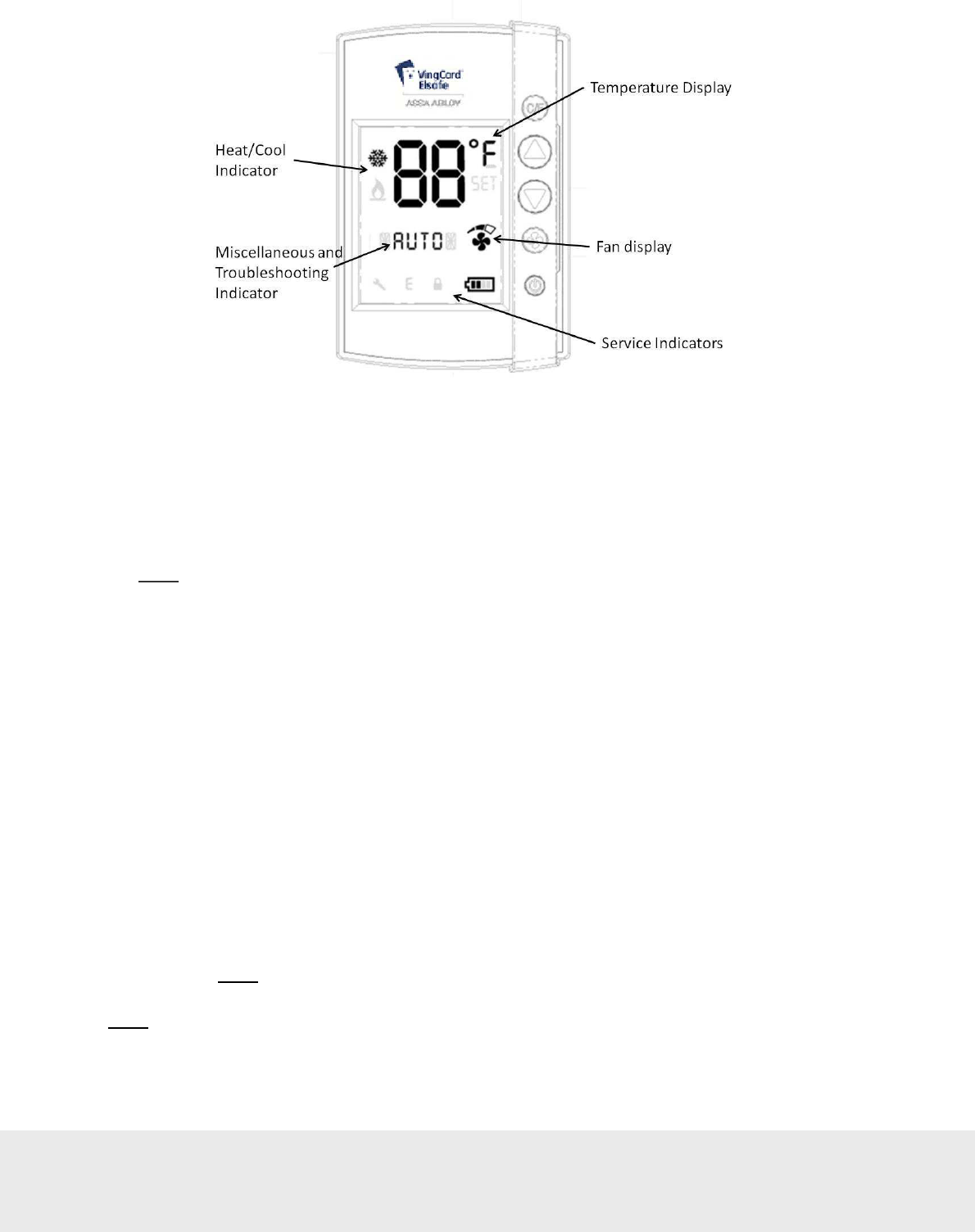
3.2.2 Thermostat display
The thermostat displays settings and operation details to the guest, such as room temperature and
heat/cool indications.
Display details:
•
Temperature Display:
The temperature display area shows the actual room temperature or the set
temperature as well as the indication of Fahrenheit or Celsius. When the displayed temperature is the
guest setting, not the actual room temperature, the SET indicator is also displayed.
Note:
Whenever a guest is changing the setting, the SET temperature will display.
•
Heat/Cool Indicator:
The thermostat displays universal icons for heating and cooling. The snow star is
the symbol to indicate the unit is in cooling mode and the flame is the symbol to indicate heating mode.
•
Fan Display:
The fan display shows the fan speed of the unit. As the fan speed increases, additional
segments or the indicator are displayed. When in AUTO fan mode, the word AUTO will appear in the
middle of the display (at the Miscellaneous Indicator, see below).
•
Miscellaneous Indicator:
The indicator in the middle of the display is a multi-purpose indicator.
It e.g. displays the word AUTO when the automatic fan mode is enabled.
•
Service indicators:
- Wrench Icon: The wrench icon is displayed when maintenance is required on any of the
EMS devices in the room or the HVAC unit. This icon is only displayed to hotel staff.
To get the details of the maintenance needed, connect the service terminal to the thermostat.
- Error (E) Indicator: The error indicator is primarily used for the battery operated thermostat
and will be displayed when communication between the thermostat and the thermostat controller
is lost. When displayed, the thermostat will turn OFF. This indicator is displayed to guests as
well as staff, as maintenance is required in order for the system to operate.
- Battery Icon: The battery icon is displayed to hotel staff when the batteries are low
(on battery powered units) and in need of replacement.
Note:
This is a low indicator only, not a segmented icon that displays the battery level.
As soon as this indicator is displayed, the batteries need to be replaced.
Note:
If the lock is not used to monitor the door status, the service indicators will only be displayed when
the service device is used - with the exception of the error (E) indicator.
Figure
3
September
1
3
, 20
12
Page
9
of
50
66 8003 00
2
-
8
3.2.3 Thermostat dimensions
Figure 4 shows the dimensions of the thermostat. The design allows the unit to be mounted onto a US or European
single gang box.
Dimensions
in mm (inches)
Figure
4

September
1
3
, 20
12
Page
10
of
50
66 8003 00
2
-
8
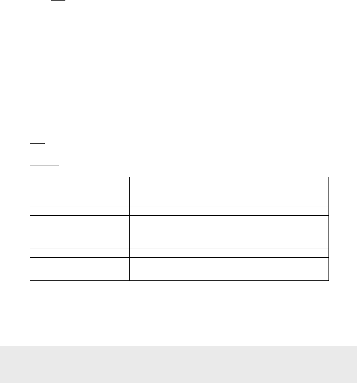
3.3 Parameters / specifications
Temperature display range 2-digit display – no limit
Guest control range*
65 – 90 ºF / 18 – 32 ºC;
configurable through service device
HVAC control types Standard H/C; heat pump
Input voltage 12-24 VAC
15-24 VDC
V+ Follows the input voltage (AC rectified)
VDC relative to GND
Outputs
W/W2 – Heating
Y/W2 – Cooling / compressor
G1 – Fan 1
G2 – Fan 2
G3 – Fan 3
RV – Reversing valve
Inputs Door switch – 1 exterior / 1 interior
Motion sensor/card switch I/O
Service connector (programming)
Temperature sensor*
Integrated in thermostat
Option: remote temperature sensor that connects
directly to the thermostat controller
RF signals
ZigBee 2006
Lock to thermostat:
• Door open – staff card
• Door open – guest card (includes check-out
date/time, suite rooms and first time use)
• Door open from inside
• Door closed
• Deadbolt thrown / released
Thermostat to lock:
• Room occupied – to enable lock to
enter AutoDND mode
Motion sensor to thermostat:
• Motion detected
• Battery status
Thermostat to motion sensor:
• Turn off when the room is occupied and
the door is closed
• Turn on when the door is opened again

September
1
3
, 20
12
Page
11
of
50
66 8003 00
2
-
8
Thermostat deadband Configurable 1 – 3 ºF; default is 2 ºF
Heat cool switching deadband Configurable 2 – 4 ºF; default is 3 ºF
Heat / cool switching Configurable to allow or disallow auto changeover
of heat/cool.
Freeze guard 39 ºF / 4 ºC
Refresh cycle Optional
Humidity* Optional
Temperature display
Configurable:
Guest setting or room temperature; default is
room temperature
Intelligent switch
Configurable:
Disabled/use RV output/use G2 output; default
is disabled
Room not occupied timer Configurable 4 – 30 minutes; default is 8 minutes
Room not sold timer Configurable 12 – 24 hours; default is 16 hours
Compressor delay (dwell-off time)
5 minutes. The dwell-off time prevents
short-cycling of the compressor; this parameter
cannot be changed
Note:
For information about where in the software to change the parameters, see the tables for basic and
advanced parameters respectively in Daily use manual Orion EMS.
*) These parameters are stored in the thermostat even if the thermostat controller is used
Table 1
September
1
3
, 20
12
Page
12
of
50
66 8003 00
2
-
8
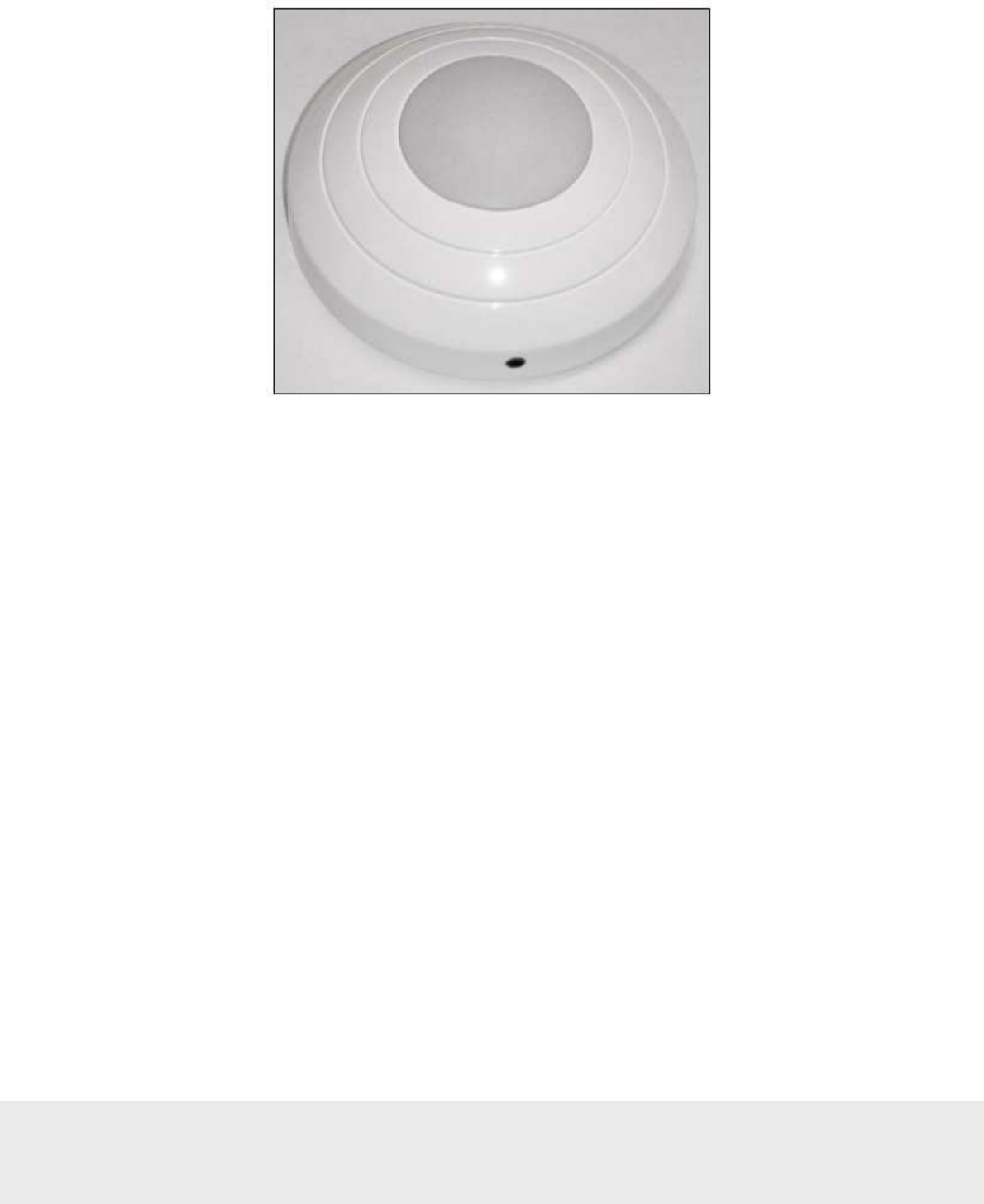
3.4 Motion sensor
The motion sensor is used to detect motion in the room and send this information via the ZigBee endnode to the
thermostat. The device is designed to be ceiling or wall mounted and is powered by 3AA batteries. No physical
connections are required; thus making the installation simple.
Figure
5
September
1
3
, 20
12
Page
13
of
50
66 8003 00
2
-
8
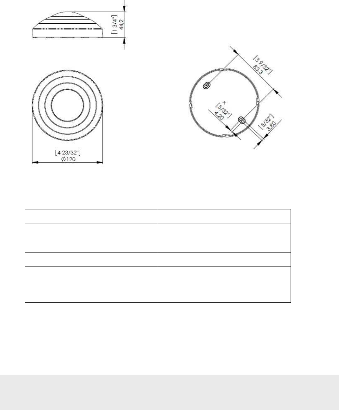
3.4.1 Motion sensor dimensions
3.4.2 Motion sensor specifications
Input power 3 AA batteries (4.5 VDC)
Mounting • Ceiling or wall surface mounting
• Keyhole type for easy installation and
battery replacement access
Range 360 degree / 8 meters horizontal / 3 meters vertical
Messages transmitted • Motion detected
• Battery status
Diagnostics Integrated LED only enabled for diagnostics
Table 2
Figure
6
Dimension
s in mm (inches)
September
1
3
, 20
12
Page
14
of
50
66 8003 00
2
-
8
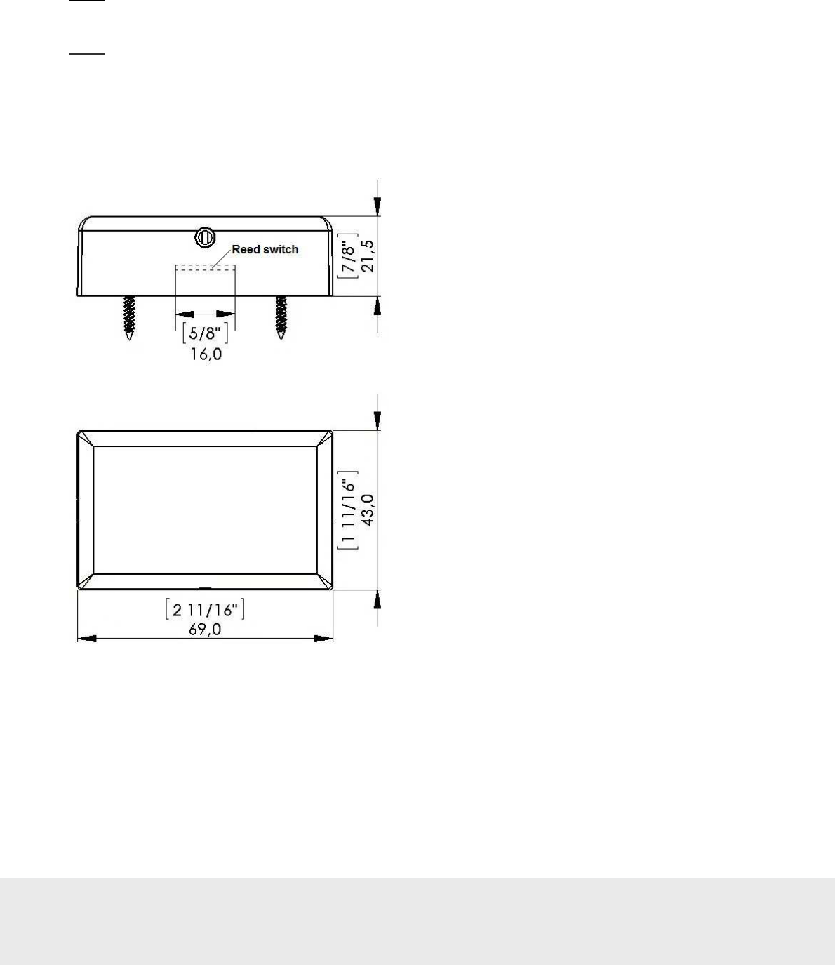
3.5 RF Door switch
If VingCard online locks are not applicable at the installation, an RF door switch can instead be used for
monitoring the position of the door. The door switch is powered by 2 AA batteries and the kit also includes
a magnet (see Figure 8) and two screws. The door switch can be mounted as it is or on a wall-mounted casing
(see Figure 9) which is purchased separately.
Note:
For best operation, the magnet should be installed maximum 10 mm (25/64″) from the reed switch which
is located as in Figure 7.
Note:
It is also possible to use a wired door switch without radio; see section 4.3.2.4 for details.
3.5.1 RF door switch dimensions
Dimension
s in mm (inches)
Figure
7
September
1
3
, 20
12
Page
15
of
50
66 8003 00
2
-
8
3.5.2 RF door switch magnet dimensions
Note:
The magnet must be mounted maximum 10 mm (25/64´´) from the door switch.
3.5.3 Wall-mounted casing
Figure
8
Dimension
s in mm (inches)
Figure
9
September
1
3
, 20
12
Page
16
of
50
66 8003 00
2
-
8
4. Device installation and commissioning
The Orion EMS thermostat is a low voltage (12-24 VAC / 15-24 VDC) device and the air handler to which it is
installed must have a low voltage interface. If no low voltage interface exists, one supplied by the distributor or
another qualified installer must be installed. The thermostat may be connected on air handlers with either standard
(on/off) control or heat pump control.
Important:
Do not connect the Orion EMS thermostat directly to high voltage as this will destroy the thermostat.
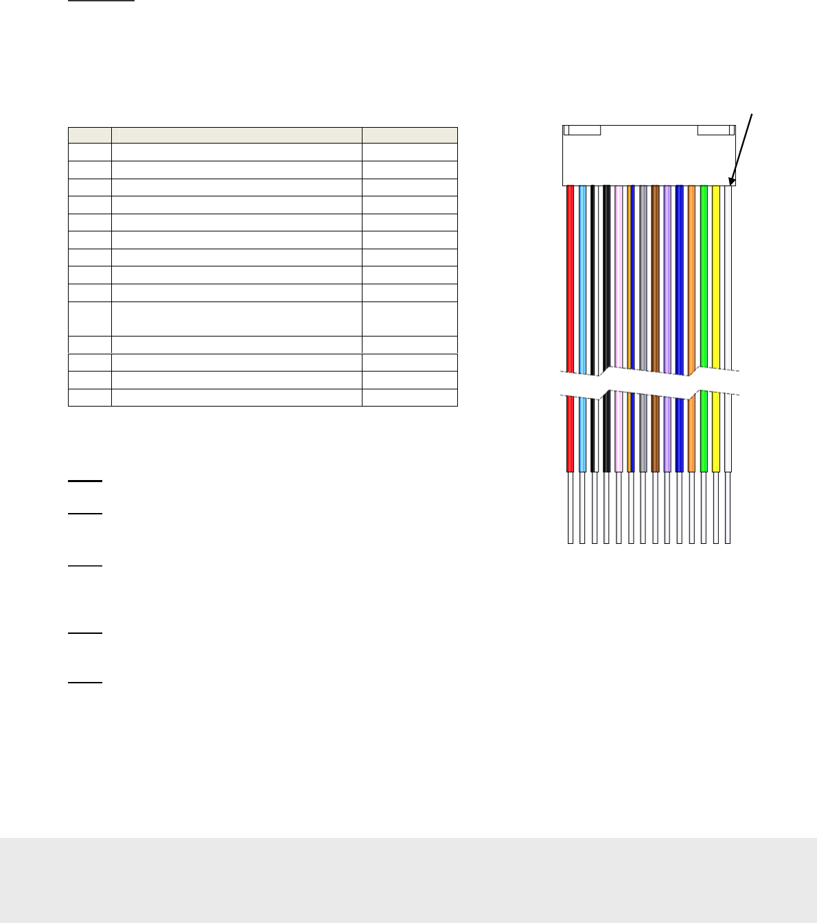
4.1 Inputs / outputs
Table 3 shows the inputs and outputs for the Orion EMS thermostat which are connected via the wiring harness
supplied with the thermostat.
Note:
V+ can be used for voltage feeding of e.g. a wired motion sensor.
Note:
All signal inputs (pins 8-10) are relative to GND (active high).
Note:
Connect input voltage 12-24 VAC or 15-24 VDC to pins 13
and 14.
Note:
If a thermostat controller is used, the wiring harness is connected at the front of the thermostat controller as
shown in Figure 13.
Note:
If no thermostat controller is used, the wiring harness is connected at the back of the thermostat as shown in
Figure 14.
Pin Input / Output Wire Color
1 W/W2: Heating (output) White
2 Y/W2: Cooling/Compressor (output) Yellow
3 G1: Fan 1/low (output) Green
4 G2: Fan 2/medium (output) Orange
5 G3:Fan 3/high (output) Dark blue
6 RV: Reversing valve (output) Violet
7 Extra output: not used Brown
8 DS_I: Interior door switch (input) Gray
9 DS_E: Exterior door switch (input) Orange/blue
10 EX1: Extra input 1 (motion sensor/
card switch I/O) Pink
11 Signal GND relative to V+ Black
12 V+ (load max 50mA DC) White/black
13 C: Power input - Light blue
14 R: Power input + Red
Figure
10
:
Wire colors of
wiring harness
PIN1
Table 3
September
1
3
, 20
12
Page
17
of
50
66 8003 00
2
-
8
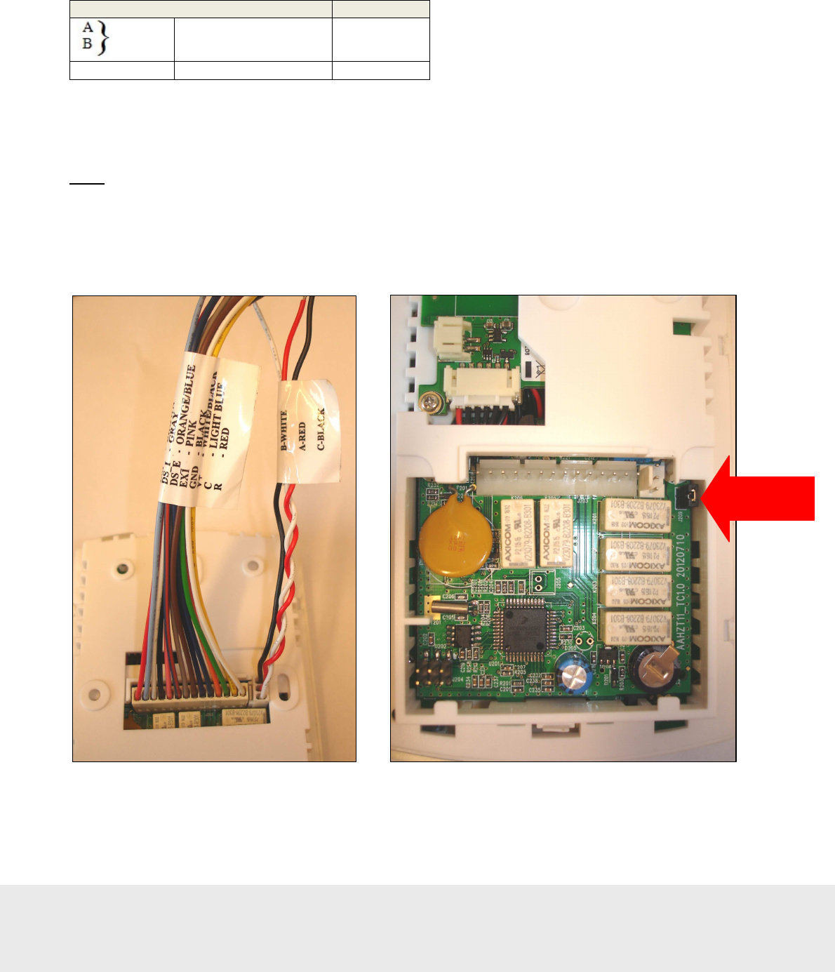
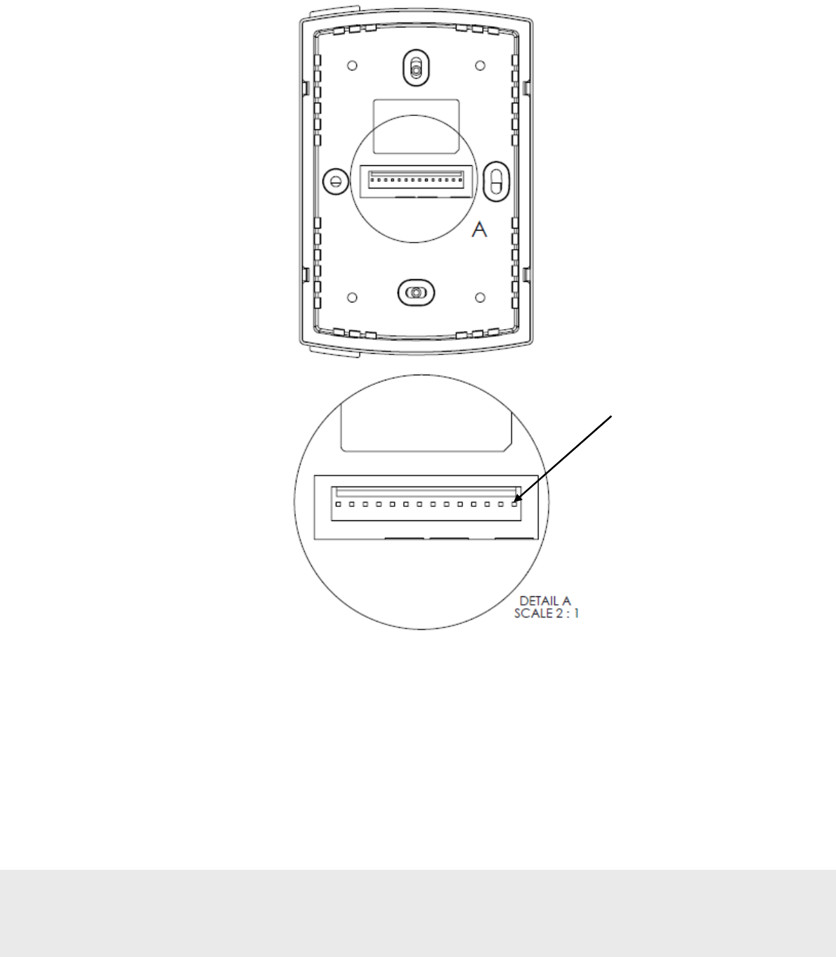
4.1.1 RS-485 interface
Next to the 14 pin contact for the wiring harness described in section 4.1, there is a 3 pin contact for RS-485
communication; see Figure 11. The three RS-485 wires which should be connected to the corresponding wires
on the 3
rd
party RS-485 equipment are described in Table 4.
A
is the
non-inverting
pin and
B
is the
inverting
pin.
Note:
For Lutron RS-485 equipment, a different naming convention is used;
MUX
and
MUX(bar)
,
where
A
=
MUX
and
B
=
MUX(bar)
.
Other 3
rd
party RS-485 equipments may use other naming conventions; please check the applicable RS-485
equipment manual for correct configuration. Swapping the
A
and
B
lines does not harm the equipment,
so the “try-and-see” approach is also useful.
Description
Wire Color
Twisted pair data bus A: Red
B: White
C Common reference Black
Figure
1
1
:
The 3 pin contact for RS
-
485
communication is located next to the
14 pin contact for the wiring harness.
Table
4
Figure
1
2
:
The j
umper
marked
with an arrow in this picture
should not be removed.
September
1
3
, 20
12
Page
18
of
50
66 8003 00
2
-
8
4.1.2 Configuration with thermostat controller
If the thermostat controller is used, the wiring harness is connected on the thermostat controller front.
PIN1
Figure
1
3
September
1
3
, 20
12
Page
19
of
50
66 8003 00
2
-
8
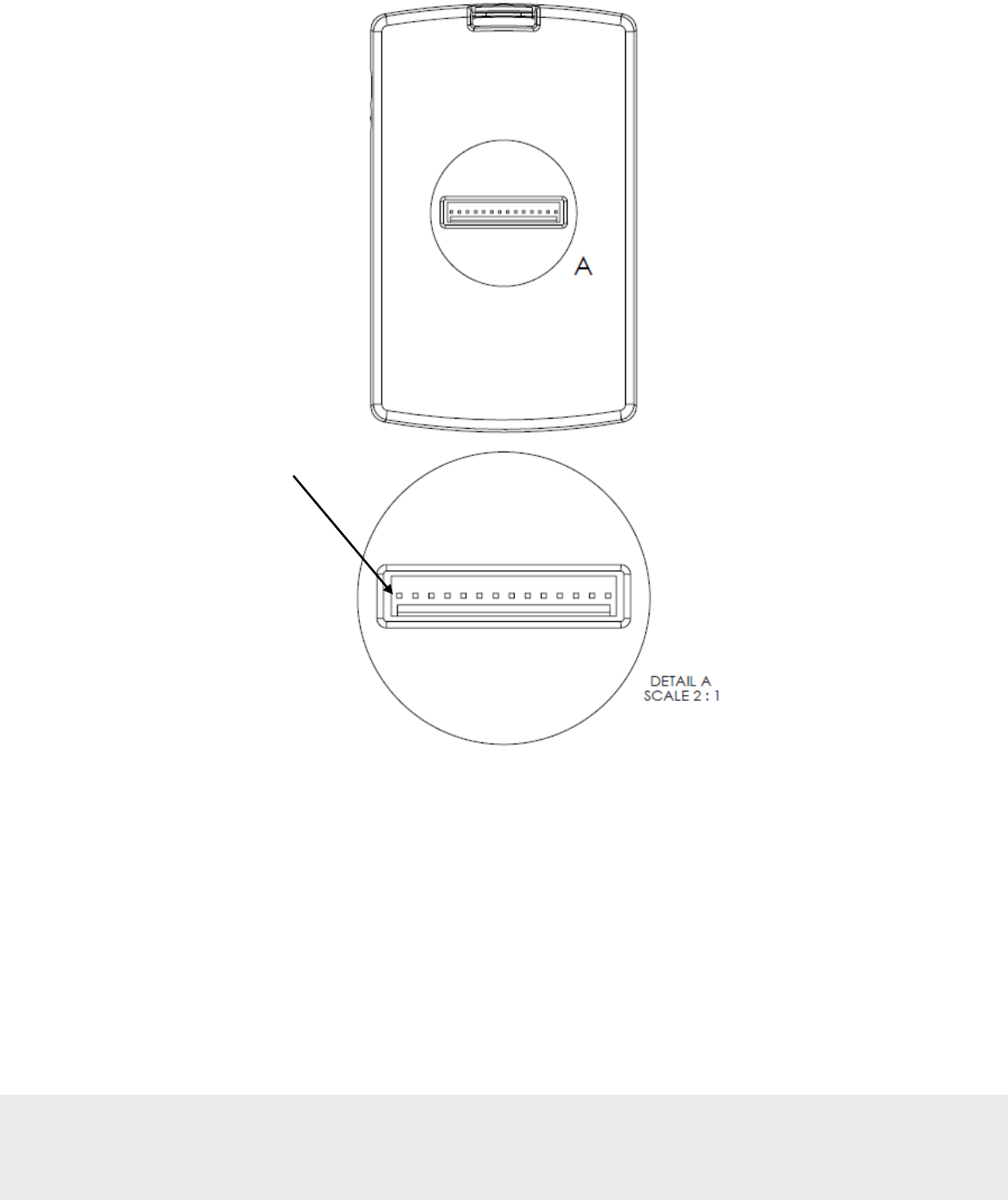
4.1.3 Configuration without thermostat controller
If no thermostat controller is used, the wiring harness is connected on the back of the thermostat.
Figure
1
4
PIN1
September
1
3
, 20
12
Page
20
of
50
66 8003 00
2
-
8
4.2 Installing a thermostat controller
Note:
The thermostat controller may not be sealed into a metal box.
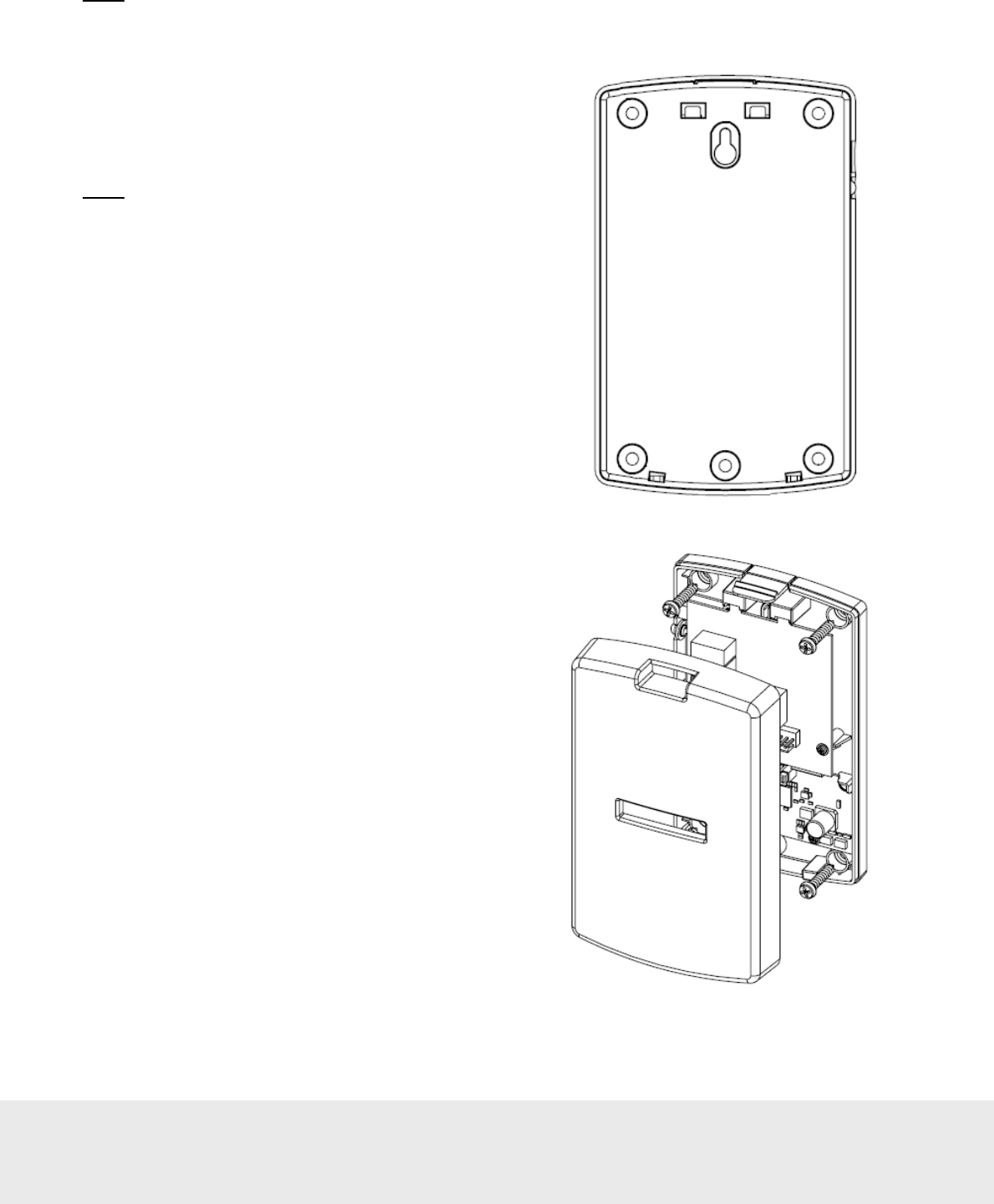
4.2.1 Mounting a thermostat controller
The thermostat controller is designed to be installed
on a standard US or European single gang switch box.
Figure 15 shows the five screw holes on the back of the
thermostat controller.
Note:
The thermostat controller may also be installed inside
an air handler as long as it in not encased in metal.
Figure 15
1. The mounting bracket is attached using five screws
and the thermostat controller can then be snapped into
place on the mounting bracket as shown in Figure 16.
2. Once the wiring harness is connected, it is best to
insert the thermostat controller on the bottom snaps
first; then press down on the top of the mounting
bracket as the top is snapped into place.
To remove a thermostat controller:
1. Press down on the top of the mounting bracket to
release the snaps and pull the top of the thermostat
controller away from the wall; then lift up to
completely remove from the bracket.
Figure
1
6
September
1
3
, 20
12
Page
21
of
50
66 8003 00
2
-
8
4.3 Installing a thermostat
The thermostat is only to be installed by qualified installers. All local codes must be followed when installing this
thermostat. The thermostat will control a variety of HVAC systems and the installation will vary based on the type
of system to which it is installed.
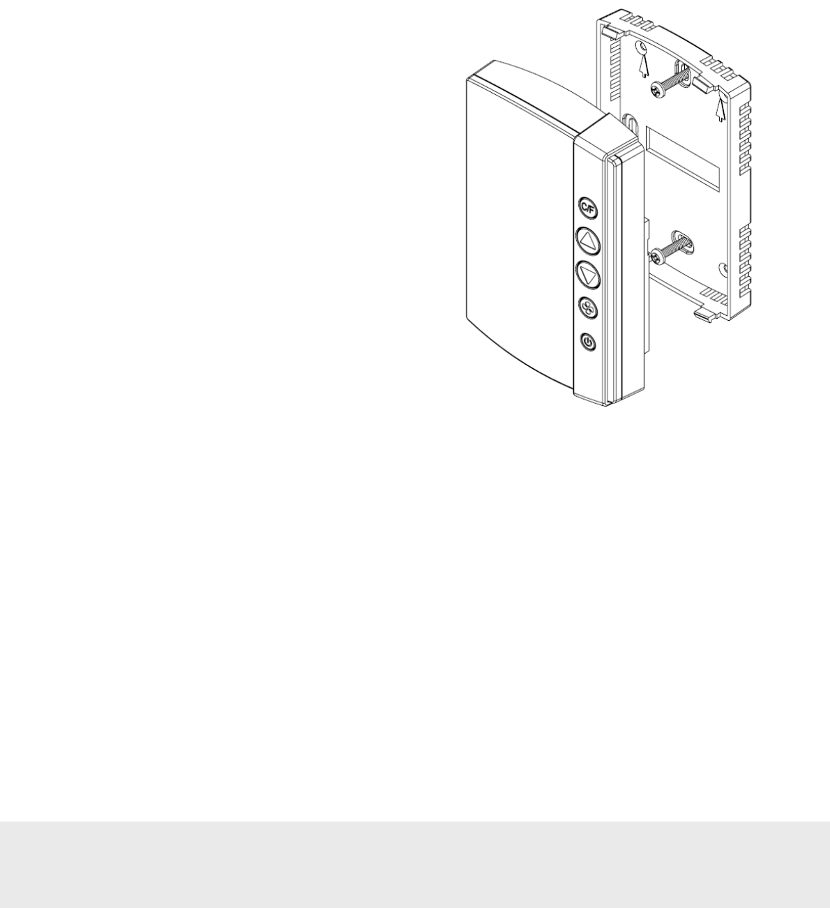
4.3.1 Mounting a thermostat
The thermostat is designed to be installed on a standard US
or European single gang switch box.
1.
The mounting bracket is attached using two screws
and the thermostat can then be snapped into place
on the mounting bracket as shown in Figure 17.
2.
Once the wiring harness is connected, it is best to
insert the thermostat on the bottom snaps first; then
press down on the top of the mounting bracket as the
top is snapped into place.
To remove a thermostat:
1.
Press down on the top of the mounting bracket to
release the snaps and pull the top of the thermostat
away from the wall; then lift up to completely
remove from the bracket.
Figure 17
September
1
3
, 20
12
Page
22
of
50
66 8003 00
2
-
8
4.3.1.1 Thermostat placement
If there are no existing thermostats, a few important items should be considered in determining placement:
• Do not mount the thermostat in the direct air flow of the air handler.
• Do not mount the thermostat in direct sunlight.
• Do not mount the thermostat directly above or behind any heat generating device such as a light or a TV.
• Generally, the thermostat should be mounted about 1.5m (5 feet) above the floor for standard rooms;
however, local codes must be followed.
Note:
When applicable, also follow local handicap requirements.
4.3.1.2 Thermostat battery exchange
To exchange the batteries in the thermostat, remove the thermostat according to section 4.3.1 and exchange the
batteries (3 AA) in the battery package.
4.3.2 Wiring a thermostat
4.3.2.1 Recommended wire specification
It is recommended to use 0,82 – 0,33 mm
2
/ 18 – 22 AWG (equivalent) solid copper wire (Plenum rated if
required by local code) from the thermostat to the HVAC system or line to low voltage interface. The same
can be used if installing a wired door switch. The number of conductors to the HVAC system will depend
on the particular installation. A 2-conductor wire is required for the wired door switch.
4.3.2.2 Connecting a thermostat
The wires of the wiring harness (Figure 10) are to be connected to the low voltage thermostat inputs of the
air handler. These include heat, cool, three fan speeds and the reversing valve (heat pump only).
Note:
If connecting to an air handler that has only two fan speeds, connect the low fan to the Fan 1 output
and the high fan to the Fan 2 output. If the air handler has only one fan speed, connect to the Fan 1 output.
Important:
If connecting to a high voltage air handler, a line to low voltage conversion kit must be used.
W/W2 (white) For standard systems, this controls HEAT. For heat pumps, this is
connected to the Stage 2 heating element if applicable.
Y/W2 (yellow) This controls the COOL function for standard control and the Compressor
for heat pump control. (For heat pumps, this is Stage 1 heating).
G1 (green) This controls fan speed 1 (low).
G2 (orange) This controls fan speed 2 (medium).
G3 (dark blue) This controls fan speed 3 (high).
RV (violet) This controls the reversing valve (heat pump only). The logic is set by
the configurable parameters when the thermostat is commissioned.
Power - Common / Ground (black)
Power (red) 12-24 VAC
15-24 VDC
Table 5
September
1
3
, 20
12
Page
23
of
50
66 8003 00
2
-
8
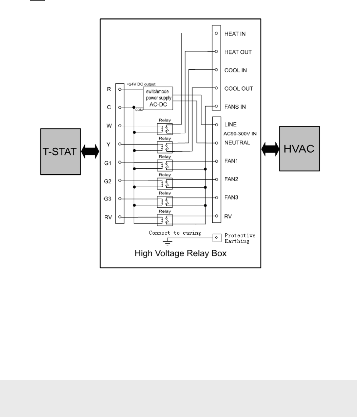
4.3.2.3 Line to low voltage conversion
Figure 18 shows the wiring diagram for connecting to a line to low voltage conversion kit. This kit is typically
located in the control box of the HVAC system or in close proximity to the unit.
Note:
Local codes must be followed when installing the line to low voltage conversion kit.
Figure 18
4.3.2.4 Connecting a wired door switch
If a wired door switch will be used to monitor the position of the door, it is recommended to use a magnetic 2-wire
door switch. These wires are connected to the thermostat wiring harness as follows:
• If the door is exterior (leads to the outside), connect the wires to the orange/blue (exterior door input) wire
and the white/black wire of the thermostat wiring harness.
• If the door is interior (leads to an interior corridor), connect the wires to the gray (interior door input) wire
and the white/black wire of the thermostat wiring harness.
Installation of the door switch will vary depending on the type of switch used. Follow the instructions provided
with the door switch to install it at the door.
September
1
3
, 20
12
Page
24
of
50
66 8003 00
2
-
8
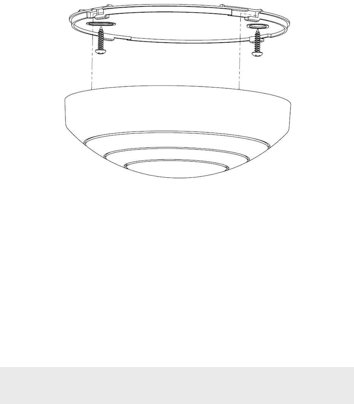
4.4 Installing a motion sensor
The motion sensor is a battery operated device that may be installed on the ceiling or wall. The mounting bracket is
installed with two screws as shown in Figure 19.
Figure 19
September
1
3
, 20
12
Page
25
of
50
66 8003 00
2
-
8
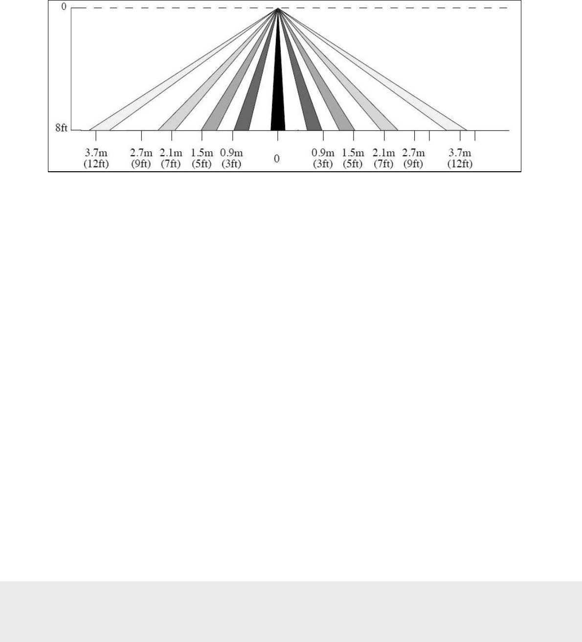
4.4.1 Motion sensor placement
For optimal coverage, the motion sensor should be installed on the ceiling as close to the middle of the room as
possible. When ceiling mounting is not feasible, either due to the construction or for the aesthetics of the room,
the sensor may be placed on the wall. The location should be as high as possible and give as much coverage to
the room as possible. Figure 20 shows the range of the motion sensor when placed on the ceiling. This range is
somewhat reduced when installed on the wall. The range shown is a general guideline, and the sensor is designed
to cover an area of about 8m (26 feet) in diameter.
To check the placement, it is advisable to activate the motion LED using the service device and test the range of
the motion sensor. This process will help to determine the best location of the sensor. See section 4.6 Testing the
In-Room Devices for instructions on this process.
Figure
20
September
1
3
, 20
12
Page
26
of
50
66 8003 00
2
-
8
4.5 Commissioning the system
Before the devices can communicate, they must be joined to the ZigBee network. For detailed instructions and rules
on this network, see User manual Online option.
Note:
The ZigBee network, including gateway and router locations, must first be specified by a qualified technician.
No online setup can be done until this step is completed.
4.5.1 Commissioning when thermostat controller is used
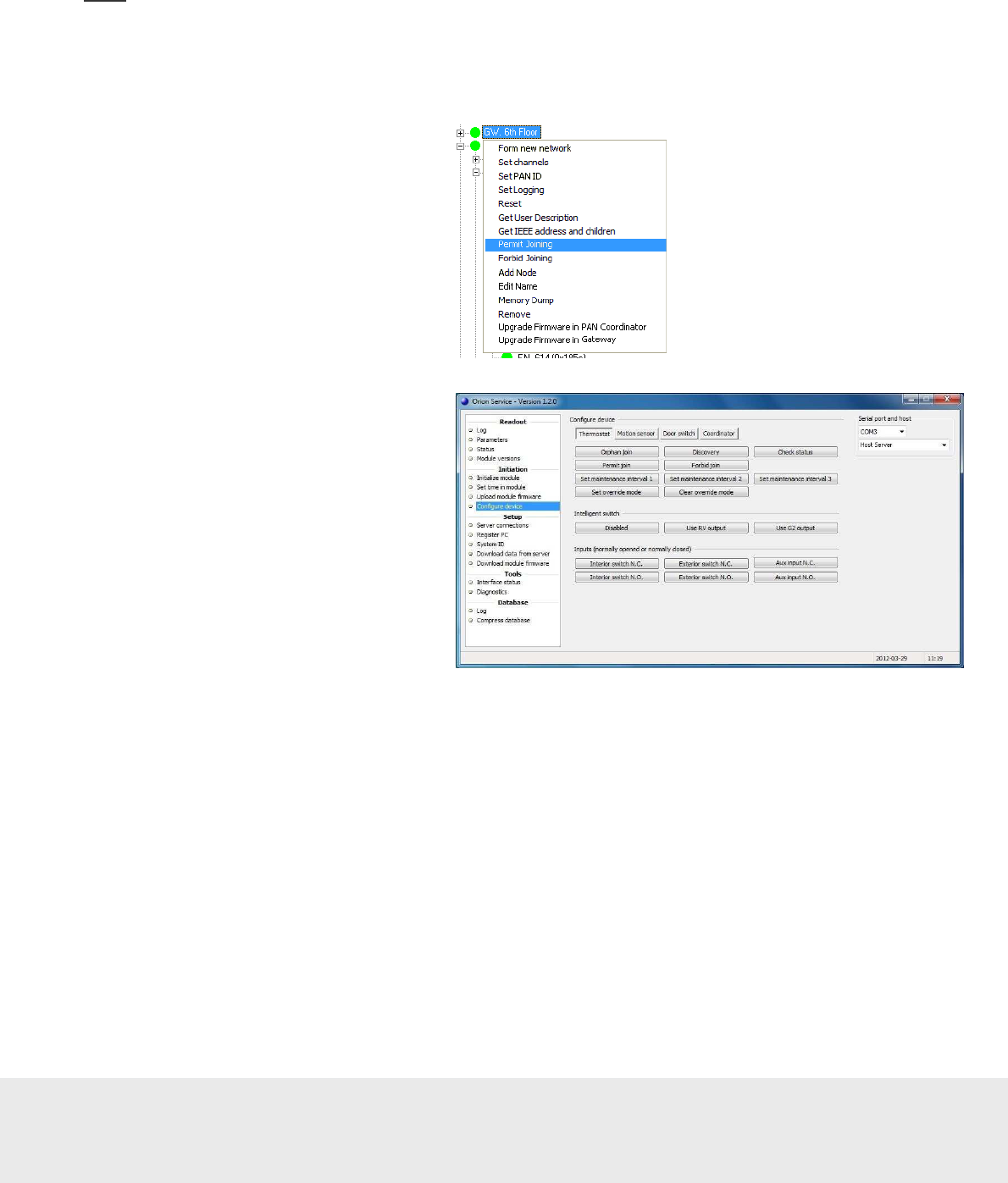
4.5.1.1 Joining the thermostat controller to the network
1. In the
ZigBee Network
window of
SysMon, right click on the applicable
gateway/router and select
Permit
Joining
. The gateway/router is now
‘open’. It will remain in this status for
approximately 15 minutes or until a
forbid join command is executed.
2. With the gateway/router open,
plug the service cable into
the thermostat controller.
Figure 21
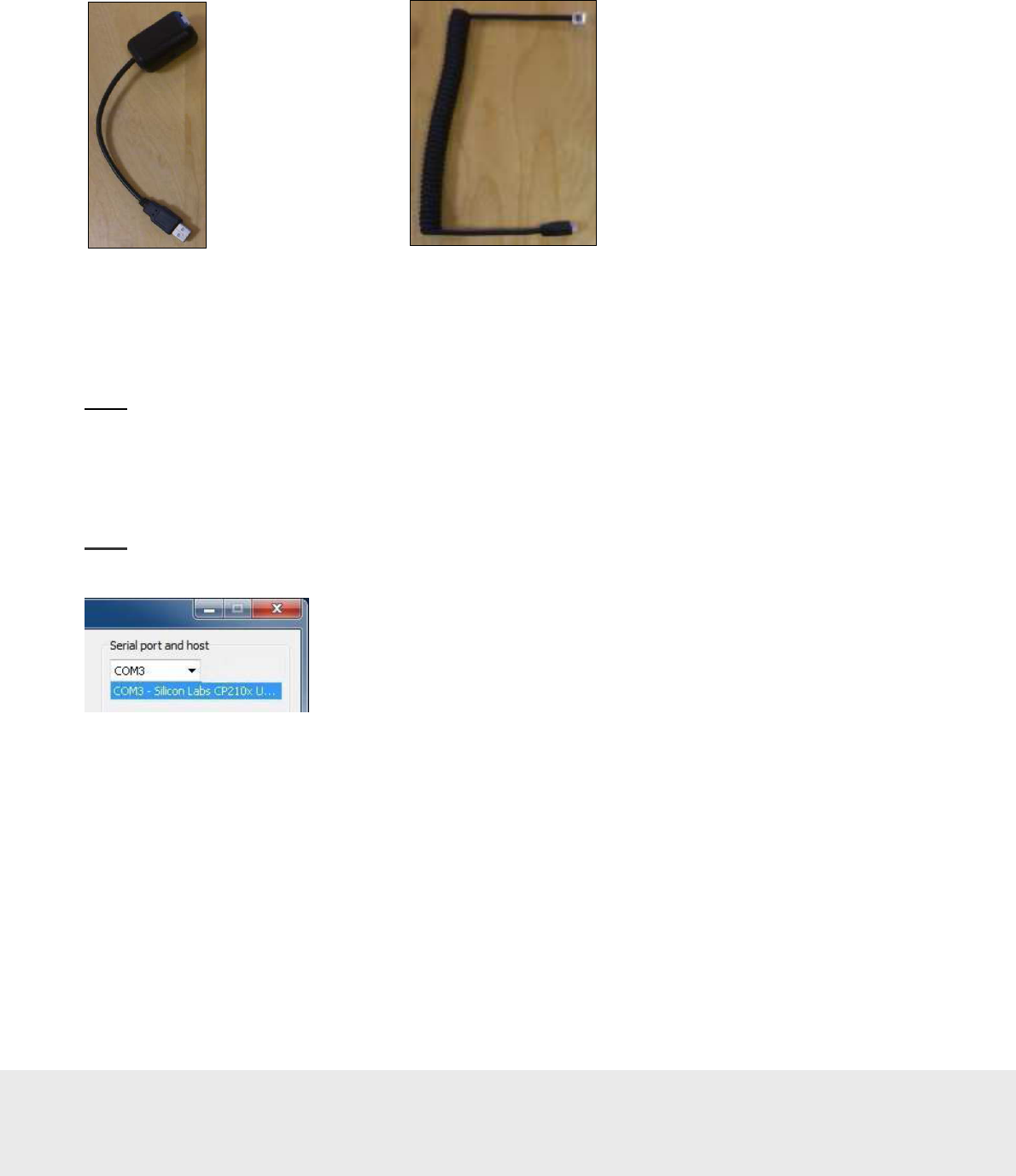
3. In the Orion Service software
(
Start/Programs/Orion Service/
Orion Service
), choose
Configure
device
in the left part of the window.
Let the tab
Thermostat
(default) be
open and click the
Discovery
button.
The thermostat controller will connect
to the open gateway/router.
Figure 22
4. To see if the thermostat controller was able to join the network, click the
Check status
button in the
Configure
Device
section of Orion Service. If the joining was successful, the message ‘Device is online’ is shown.
5. With the thermostat controller joined to its gateway/router, right click on the gateway/router in SysMon
and select
Forbid Joining
.
September
1
3
, 20
12
Page
27
of
50
66 8003 00
2
-
8
4.5.1.2 Joining the in-room devices to the thermostat controller
The next step is to join the in-room devices, e.g. thermostats, motion sensors and locks (or RF door switches,
if this is applicable).
Note:
When the thermostat controller is applicable, the thermostat has an endnode firmware. The thermostat controller
has either a router firmware or a coordinator firmware, depending on scenario. The coordinator firmware is for offline
scenarios when there is no connection to the server; see Appendix C for details about setting up the in-room network in
that case.
1. Plug the service cable into the thermostat controller.
2. Click the
Permit Join
button in the
Configure device
section (
Thermostat
tab) of Orion Service;
see picture in 4.5.1.1.
Note:
The thermostat controller will remain open for 15 minutes or until a forbid join command is received.
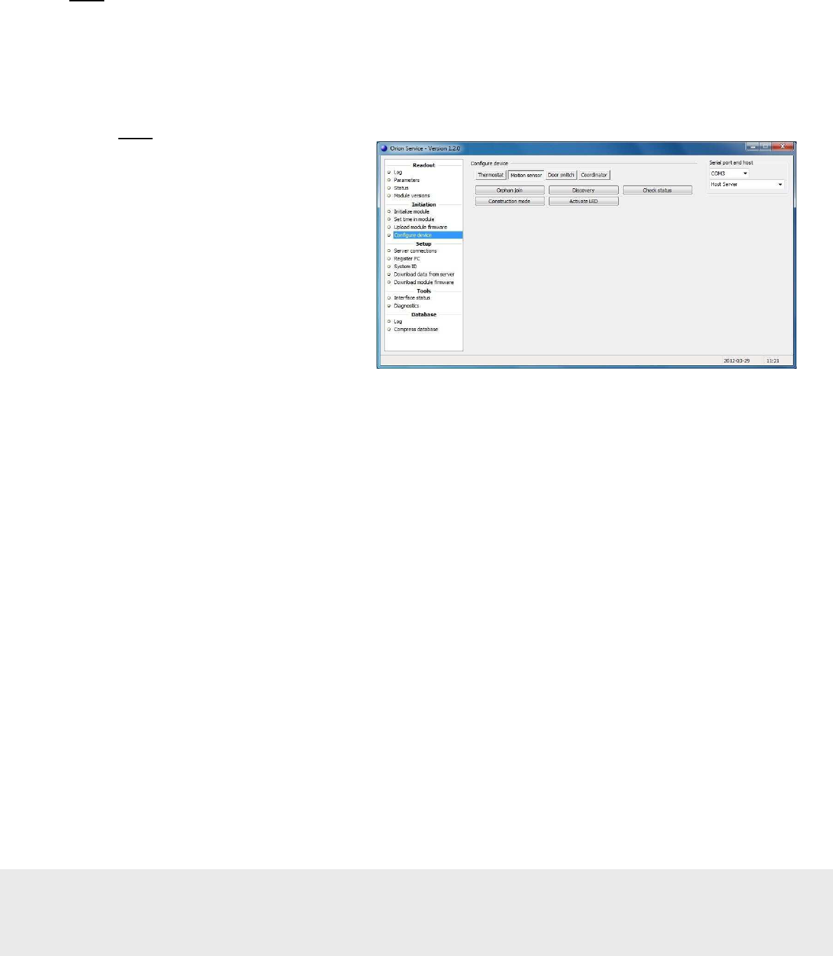
3. Once the thermostat controller has
been opened for joining, plug the
service cable into the applicable
in-room device. Choose the
Motion
sensor
tab in the
Configure device
section of Orion Service; click the
Discovery
button.
4. Wait a few seconds and then click the
Check status
button. If the device has
joined successfully, the message
‘Device is online’ is shown. If that
message is not displayed, wait a few
more seconds and check the status
again. If the device is still offline,
repeat the discovery process.
5. Join the lock and use an Enable EMI
events card in it; details are found in
the section Enabling EMI events via
card in Appendix C.
6. If an RF door switch is applicable
instead of a lock, repeat steps 3-5
with the RF door switch; in step 4,
use the
Door switch
tab.
7. Click the
Forbid join
button under
the
Thermostat
tab in the
Configure
device
section of Orion Service; see
picture in 4.5.1.1.
8. Test the in-room devices; details are
found in section 4.6.
Figure 23
September
1
3
, 20
12
Page
28
of
50
66 8003 00
2
-
8
Figure
2
4
4.5.2 Commissioning when thermostat controller is not used
The thermostat is equipped with a ZigBee endnode which can have either router firmware or coordinator firmware.
The coordinator firmware is for offline scenarios when there is no connection to the server; see Appendix C for details
about setting up the in-room network in that case.
The thermostat may be joined directly to a gateway, router or another thermostat as specified in the network layout.
The thermostat is the primary device in the room, and the lock and motion sensor will be joined to this thermostat.
When the steps in sections 4.5.2.1 and 4.5.2.2 have been performed, the in-room network is operational.
Note:
To use the Orion Service software which is mentioned in step 4 below, connections to the application server
must be made according to Appendix A.
4.5.2.1 Joining the thermostat to the network
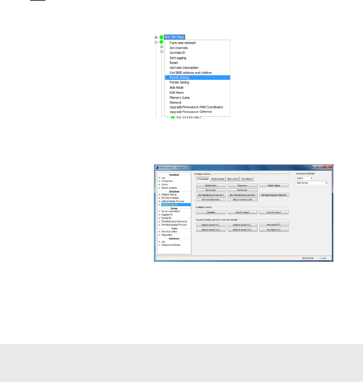
1. To be able to join the thermostat
to the gateway or router, it is first
necessary to permit joining on the
gateway or router. This is done
in the SystemMonitor, SysMon;
to open this, double click on
SysMon.exe
in the software
installation folder and log on at
File/Log on
. In SysMon, choose
View/ZigBee
to see the ZigBee
network. Right click on the
designated gateway/router in the
ZigBee Network
dialog and select
Permit Joining
in the right-click
menu; see Figure 24.
2. When the gateway/router has been set in the permit joining mode, it is “open”. It will
remain in this status for approximately 15 minutes or until a forbid join command is executed.
3. With the gateway/router open, plug the service cable into the thermostat.
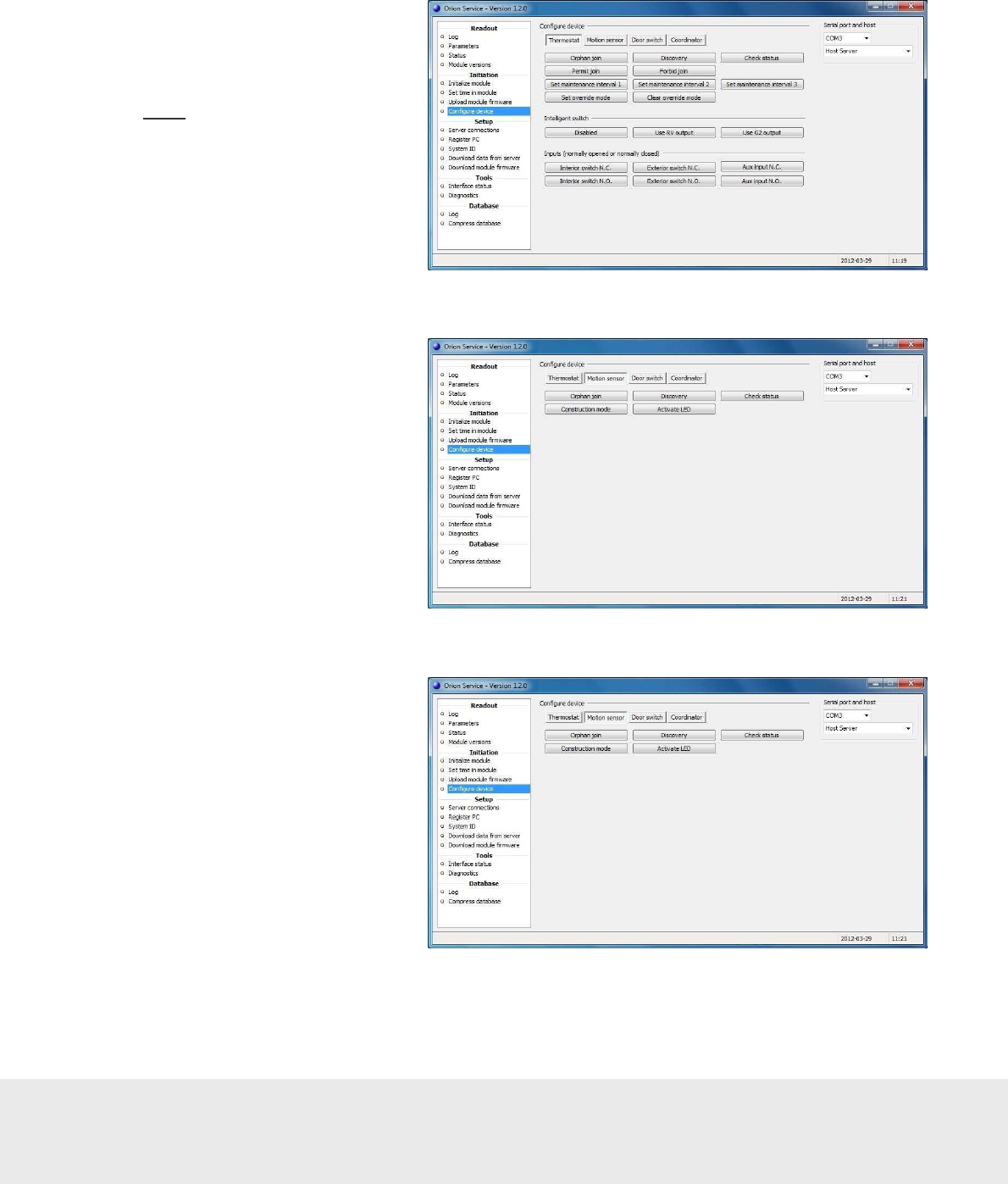
4. In the Orion Service software (go
to
Start/Programs/Orion Service/
Orion Service
), choose
Configure
device
in the left pane of the
window. Let the tab
Thermostat
(default) be open and click the
Discovery
button; see Figure 25.
The thermostat will connect to the
open gateway/router.
5. To see if the thermostat was able to
join the network, click the
Check
status
button in the
Configure
Device
section of Orion Service.
If the joining was successful,
the message ‘Device is online’
is shown.
6. With the thermostat joined to its gateway/router, right click on the gateway/router in SysMon and select
Forbid Joining
.
Figure
2
5
September
1
3
, 20
12
Page
29
of
50
66 8003 00
2
-
8
4.5.2.2 Joining the in-room devices to the thermostat
Next, the in-room devices must be joined to the thermostat, e.g. motion sensors and locks (or RF door switches,
if this is applicable).
1. Plug the service cable
into the thermostat.
2. Click the
Permit Join
button in
the
Configure device
section
of Orion Service; see Figure 26.
Note:
The thermostat will remain
open for 15 minutes or until a
Forbid Join
command is received.
Figure 26
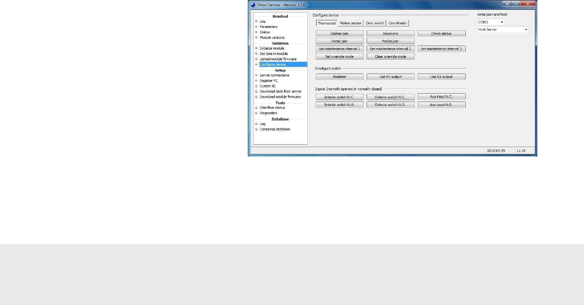
3. Once the thermostat has been
opened for joining, plug the
service cable into the motion sensor.
4. Choose the
Motion sensor
tab in
the
Configure device
section of
Orion Service. Click the
Discovery
button; see Figure 27.
Figure 27
5. Wait a few seconds and then click
the
Check status
button in the
Motion sensor
tab of
Configure
device
; see Figure 28. If the device
has joined successfully, the message
‘Device is online’ is shown. If that
message is not displayed, wait a few
more seconds and check the status
again. If still offline, repeat the
discovery process.
Figure 28
September
1
3
, 20
12
Page
30
of
50
66 8003 00
2
-
8
6.
The lock is joined to the thermostat
by using a Discovery card (one of
the ZigBee configuration cards; see
User manual Online option for
information about issuing the card).
For mag/smart locks the card is
inserted into the card reader, and for
RFID locks the card is placed
against the reader. There will
depending on lock model be a green
flash and/or a chirp, indicating that
the lock has been set into discovery
mode. Wait
a few seconds and then present the
Check Status card (one of the
ZigBee configuration cards) at the
lock. If the light flashes the green
light only and/or
a chirp is heard, the lock has
successfully joined the network. If
you instead see a green flash
followed by red flashes, and/or a
beep is heard, the lock has not
joined. In this case, wait a few
seconds and then try the Check
Status card again. If still not
successful, repeat the discovery
process.
7. In order for the lock to send door
events to the thermostats, EMI
events must be enabled. This is
achieved by presenting an Enable
EMI events card (one of the ZigBee
configuration cards) at the lock.
8. If an RF door switch is applicable
instead of a lock, repeat steps 3-5
with the RF door switch; in step 4,
use the
Door switch
tab.
9. Once the devices have been
successfully joined, plug the
service cable into the thermostat.
10. Choose the
Thermostat
tab of the
Configure device
section in Orion
Service. Click the
Forbid Join
button; see Figure 29. Failure to
perform this step will result in
problems when setting up the
network in nearby rooms.
11. Right click on the thermostat
and choose
Get user description
.
Make sure that the description says
‘no’ at ‘Join permitted’.
Figure 29
September
1
3
, 20
12
Page
31
of
50
66 8003 00
2
-
8
4.6 Testing the in-room devices
With the network successfully formed, it is now possible to test the devices to ensure proper functionality.
1. Open and close the door.
2. Engage and disengage the deadbolt.
3. Walk around the room to ensure a motion event.
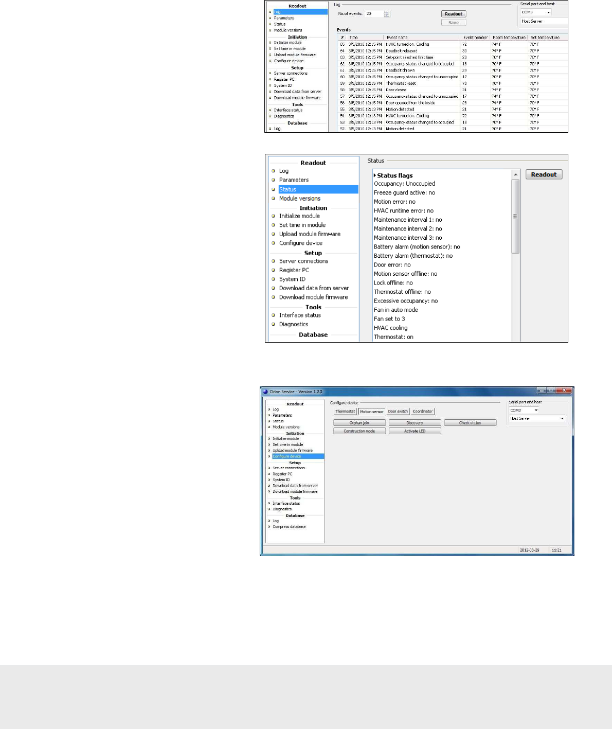
4. Run an event log of the thermostat
using the service device. To make
this, plug the service cable into the
thermostat, choose the
Log
section
under
Readout
in the left part of
the Orion Service window, choose
the applicable
No. of events
and click the
Readout
button.
Ensure that the door and motion
events are logged as shown in the
example in Figure 30. Figure 30
5. Run a status check by selecting the
Status
section in the left part of the
Orion Service software window,
making sure that the service cable
is plugged into the thermostat and
clicking the
Readout
button. Make
sure that the motion sensor, lock and
thermostat all say ‘Offline: No’; see
Figure 31.
Figure 31
6. Test the range of the motion sensor. First, make sure that the door is open as this will ensure that the
motion sensor is not deactivated by the thermostat.
7. Go to the
Configure device
section
in the left part of the Orion Service
software window and choose the
Motion sensor
tab. Make sure
that the service cable is plugged
into the motion sensor and click the
Activate LED
button; see Figure 32.
Figure 32
2
8. Walk around the room; the LED of the motion sensor will light up as motion is detected. Ensure that
the range is sufficient to pick up motion in the room. The LED will be active for 10 minutes and then
automatically turn off.
9. The system is now ready for use.
September
1
3
, 20
12
Page
32
of
50
66 8003 00
2
-
8
Appendix A: Orion Service connections
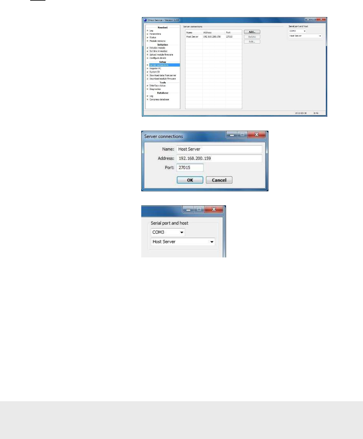
The service device is connected to the server via LAN, and to the USB interface via a USB port. When
communicating with a thermostat/motion sensor/RF door switch, a service cable is connected to the USB interface.
There are two variants of USB interface. The appearance of the item is the same in both cases, but in Orion Service
it looks different at ‘Serial port and host’ (see screenshots below) depending on what variant that is used.
Note:
For setup of the host server, see Server connections below. For more information about choosing serial port
and server, see section Register PC in this appendix.
Orion Service accesses the USB interface through a virtual COM port. Drivers must be installed to enable the
communication between service device and USB interface. The drivers are called CP210x USB to UART Bridge
Virtual COM Port (VCP) and can be downloaded for free from the Silicon Labs web site. They are also included
on the software CD.
Note:
Installation of the drivers must be made before connecting the USB interface to the service device. Once the
drivers have been installed, the USB interface must always be connected to the service device when Orion Service
is running.
USB interface
Art. No: 686 001 026
Service cable
Art. No: 205 999 005
September
1
3
, 20
12
Page
33
of
50
66 8003 00
2
-
8
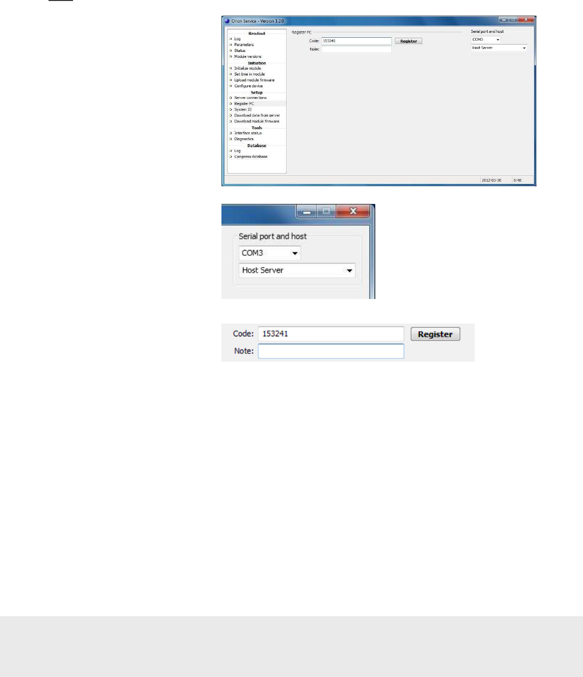
Server connections
To connect a service device to the server, there must be a service device host in the device list of the software.
Note:
The service device host must be added to a PC with static IP address. See section Set up a service device
in this appendix for information on how the service device host is set up in the software.
1. To add a connection, click
the
Add
button and enter
server data.
2. To remove a connection,
select the connection and
click the
Delete
button.
3. To edit a connection, select the
connection and click the
Edit
button. The dialog to the right
is shown; enter the new
information and click
OK
.
4. In the upper right corner of the
Orion Service window, click
R
to refresh the dialog and choose
the COM port which says
‘Silicon Labs CP210x…”
September
1
3
, 20
12
Page
34
of
50
66 8003 00
2
-
8
Register PC
The service device must be authenticated with a registration code in order to connect with the server. The
registration code is generated from the software; see section Set up a service device in this appendix for details.
Note:
This procedure is only needed once.
1. Enter the
Code
.
2. Enter a
Note
; this is optional.
3. Choose serial port and server
for the USB interface.
4. Click the
Register
button.
September
1
3
, 20
12
Page
35
of
50
66 8003 00
2
-
8
Set up a service device
Before a service device with Orion Service can be used, a service device host must be available in the device list of
the software. The service device must also be registered with a registration code which is generated in the software.
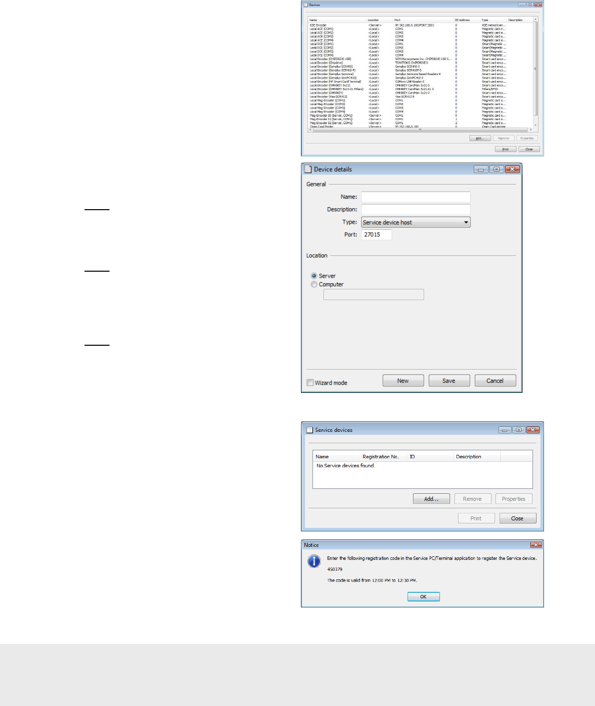
To add a service device host to the device list:
1. Double click on
Devices
under the
Lists
tab in the navigation window.
2. In the
Devices
dialog which is shown, click
Add
to add a new service device host to the
system. The
Device details
dialog is shown.
Note:
If desired, mark the ‘Wizard mode’
check box to get more detailed help.
3. Enter a
Name
for the service device host.
4. At
Type
, choose “Service device host”.
If possible, use the default port.
Note:
Make sure that you use a unique port.
5. Choose
Location
for the service device;
normally ‘Server’ should be chosen.
If there are firewalls in the system, ‘Computer’
could be chosen – in
this case, also enter the computer name.
Note:
In some cases, several devices
might be needed due to firewalls etc.
6. Click
Save
, or
Update
if an existing
service device host was redefined.
7. Click
Close
.
To register the service device:
1. Double click on
Service devices
under
the
Lists
tab in the navigation window.
2. In the
Service devices
dialog, click
Add
.
3. A registration code is generated and shown
in a dialog. The code has to be keyed into the
service device within a given time interval; see
section Register PC in this appendix for details.
When this is done, the service device will pop
up in the service device list and will be ready
for use.
September
1
3
, 20
12
Page
36
of
50
66 8003 00
2
-
8
Appendix B: Firmware upgrade
At delivery, the thermostat and the motion sensor contain the correct module firmware. However, if a firmware
upgrade is needed at a later occasion, the service device with Orion Service is used. There are two ways to
download the module firmware to Orion Service:
• The first method is to save the module firmware on the VISIONLINE server, and then download
it from there to Orion Service
• The second method is to upload the module firmware from e.g. a USB memory
Note:
Upgrading the
end node firmware in the thermostat may take several minutes.
Note:
If thermostat controller is applicable, and the firmware in this as well as in the thermostat should
be upgraded at the same time, it is recommended to start upgrading the thermostat controller first.
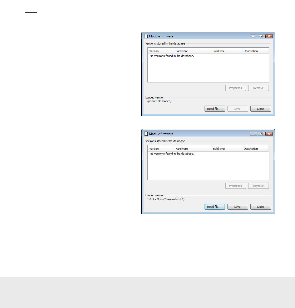
To first save the firmware on the VISIONLINE
server and then download it from there to
Orion Service:
1. Go to
Tools/Module firmware
in the
VISIONLINE software. The dialog to
the right is shown.
2. Click
Read file
and browse to the
applicable module firmware file; tmf file.
3. Mark the tmf file and click
Open
. The
tmf file will be read into the memory
and the tmf version will appear at
“Loaded version” in the lower left
corner of the
Module firmware
dialog.
September
1
3
, 20
12
Page
37
of
50
66 8003 00
2
-
8
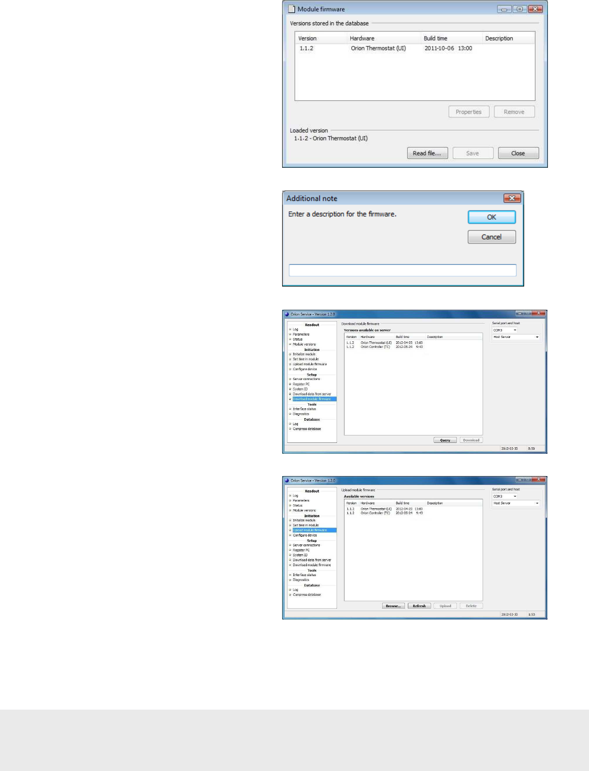
4. Click
Save
to store the tmf version in the
database. The version will appear in the list
below “Versions stored in the database” in
the
Module firmware
dialog.
5. To enter an optional description for the
tmf version, mark the version in the
Module firmware
dialog and click the
Properties
button. The
Additional note
dialog to the right is shown. Enter a
description and click
OK
.
6. In the Orion Service software, choose
Download module firmware
. Click
Query
to list the available module firmware
versions on the VISIONLINE server.
7. Mark the applicable firmware version
and click
Download
.
8. If applicable, repeat step 7 with other
firmware that is to be uploaded.
9. Plug the service cable into the thermostat or
motion sensor, depending on which module
that is to be upgraded.
10. In the Orion Service software, choose
Upload module firmware
. The firmware
version(s) that have been downloaded
according to step 7 above will be shown.
Mark the applicable firmware version and
click
Upload
.
September
1
3
, 20
12
Page
38
of
50
66 8003 00
2
-
8
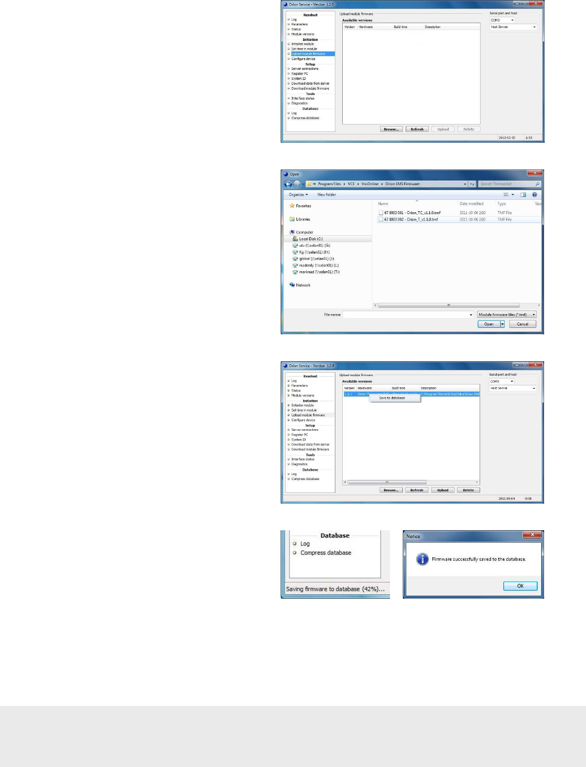
To upload the module firmware directly from
a USB memory etc:
1. In the Orion Service software, choose
Upload module firmware
.
2. Click
Browse
and browse to where the
applicable firmware file is located. Mark
the file and click
Open
.
3. To save the firmware file to the
database, right click on it and
choose
Save to
database
.
4. Down to the left in the
Lock Service
window, it will be shown how
far the
save process has reached. When the
firmware has been successfully saved,
there will be an alert about this.
September
1
3
, 20
12
Page
39
of
50
66 8003 00
2
-
8
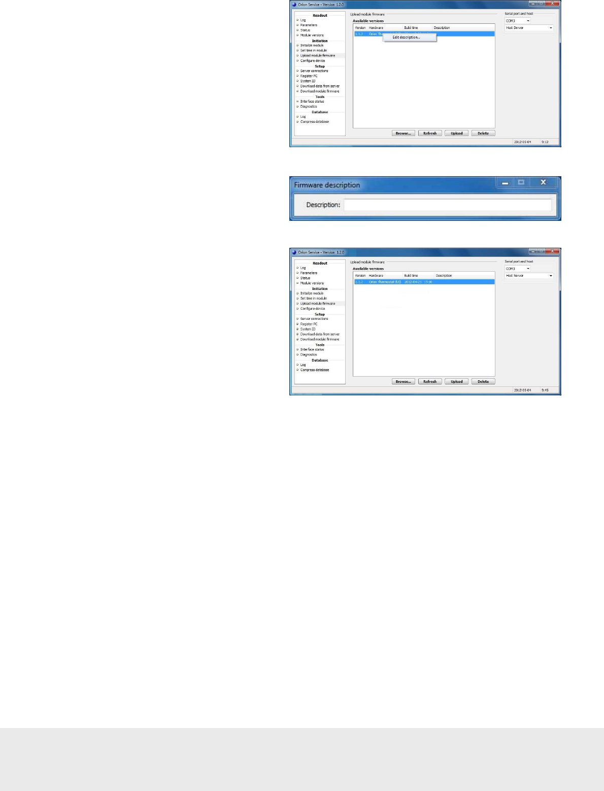
5. To add/edit the description for the
firmware, right click on the firmware
when it has been saved to the database
and choose
Edit description
.
6. Write the applicable description and
click
Enter
.
7. To upload new module firmware to
the lock, select module version in the
Available versions
list and click the
Upload
button.
September
1
3
, 20
12
Page
40
of
50
66 8003 00
2
-
8
Appendix C: Configuration in offline scenarios
In Orion EMS offline scenarios, there is no connection to the VISIONLINE server. Either a wired thermostat or a
thermostat controller and a battery thermostat is used. Each room can be seen as a PAN (personal area network)
which is controlled by its wired thermostat or its thermostat controller, depending on what scenario that is applicable.
The firmware in the wired thermostat or the thermostat controller is a coordinator firmware instead of a
router firmware.
The RFID lock in the configuration pictures above must be prepared in two ways:
•
it must be online with the in-room network; see the applicable one of sections Scenario with wired
thermostat and Scenario with battery thermostat.
•
EMI events must be enabled in the lock. This can be done either with an Enable EMI events card
or via Lock Service; see the applicable one of sections Enabling EMI events via card and Enabling
EMI events via Lock Service.
Note:
The EMI events will be sent to the closest parent in the in-room network, since there is no connection
to the VISIONLINE server.
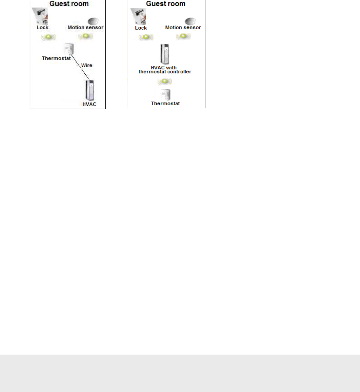
Offline scenario with
wired thermostat
Offline scenario
with thermostat controller
and battery thermostat
September
1
3
, 20
12
Page
41
of
50
66 8003 00
2
-
8
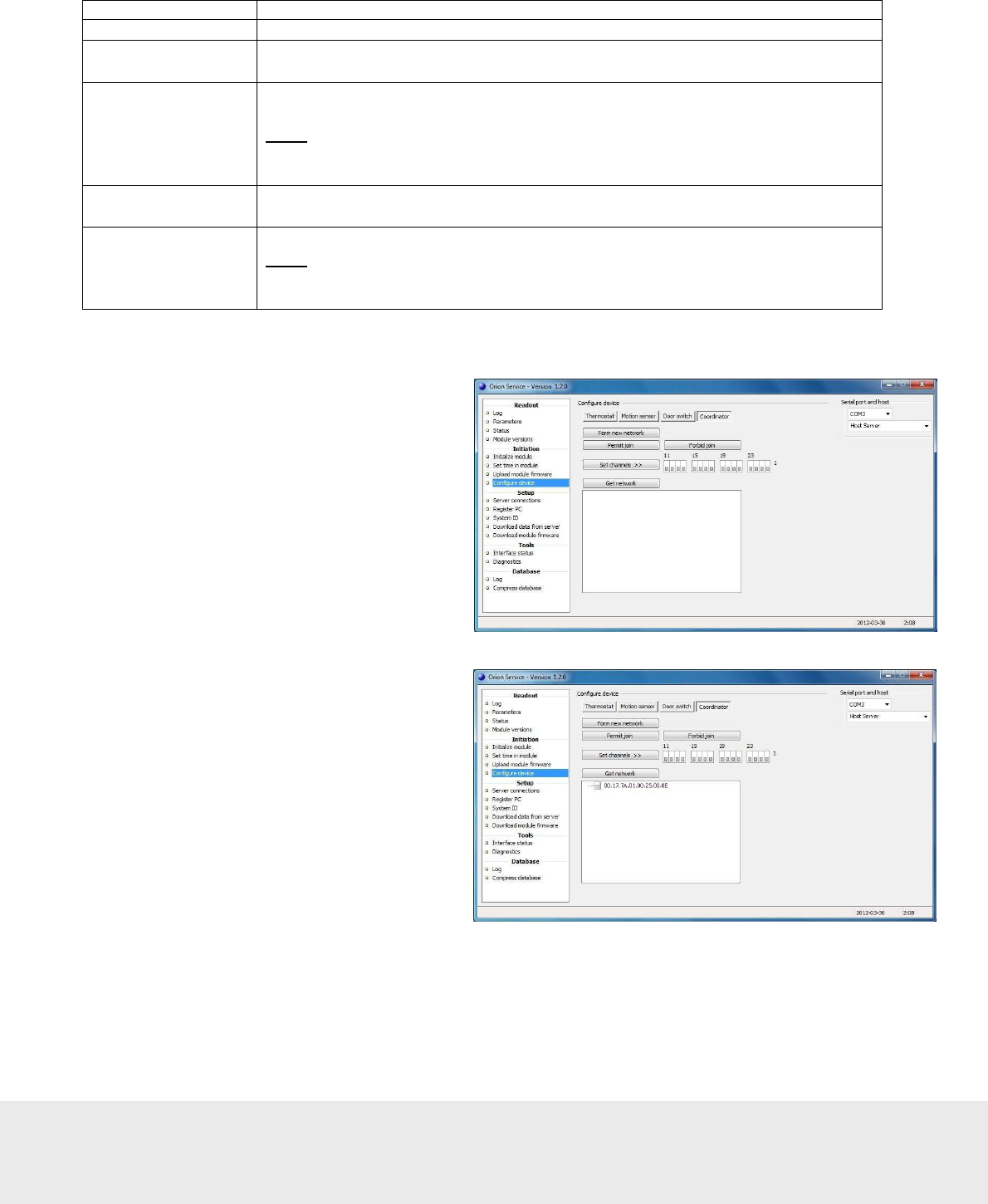
Adding the lock to the in-room network
The in-room network is configured under the
Configure device
section in Orion Service.
Configuration Description
Form new network This configuration removes all nodes in the PAN and resets the coordinator.
Permit join When this configuration is used, an in-room device (RF door switch,
motion sensor or lock) can join the coordinator.
Forbid join When the RF door switch, motion sensor or lock has joined the coordinator,
this configuration should be used on the coordinator.
Note:
If the
Forbid join
command is for some reason forgotten, it will
automatically be executed 15 minutes after the
Permit join
command
was executed.
Set channels
Default is that all channels are ON (the ‘1’ indicates ON); the best channel will
automatically be chosen, so normally the
Set channels
command is not needed.
Get network This configuration shows the in-room network.
Note:
When hovering with the cursor over an item in the network, the tooltip
will show what type of item it is; e.g. ‘Coordinator’ as in the screenshot example
above. The tooltip will also show e.g. IEEE address and firmware version.
Scenario with wired thermostat
1. Go to
Start/Programs/
Orion Service/Orion Service
.
2. Choose
Configure device
in the left
pane of the Orion Service window.
3. Plug the service cable into the thermostat.
4. Choose the
Coordinator
tab.
5. Click
Form new network
.
6. Click the
Get network
button; the
thermostat will appear in the window
below
Get network
.
September
1
3
, 20
12
Page
42
of
50
66 8003 00
2
-
8
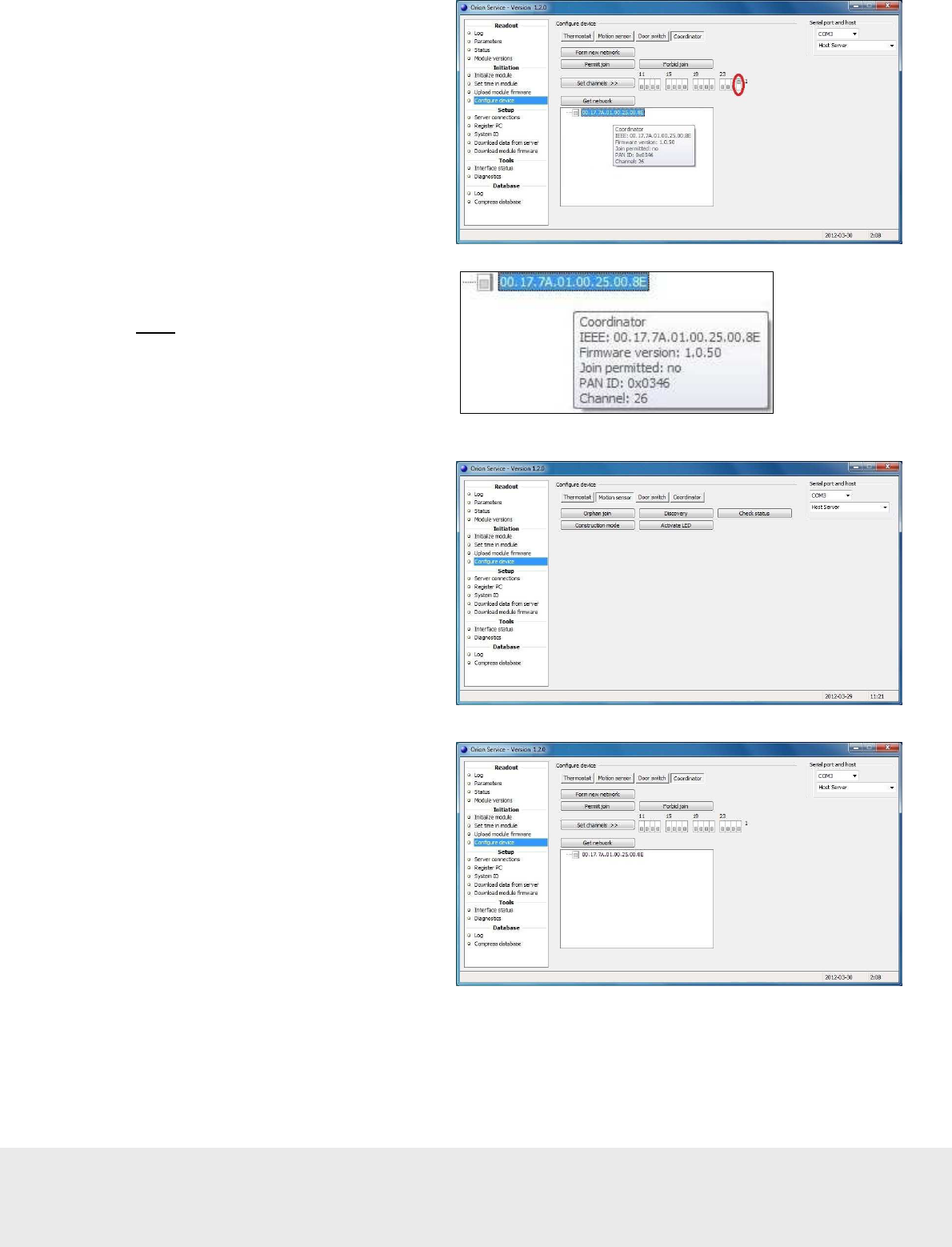
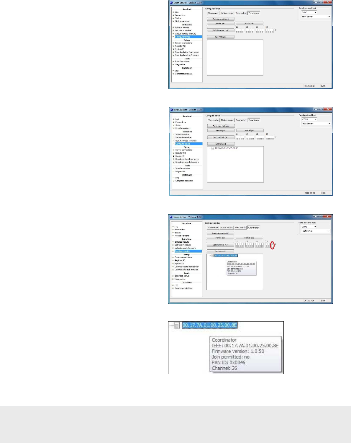
7. Put the cursor on the thermostat in the
Orion Service window; an information
box, showing e.g. the thermostat channel,
will appear. If the channel should be
changed, click the applicable channel
(in the picture example ‘26’) and
click the
Set channels
button.
8. Mark the thermostat and click the
Permit join
button.
9. Right click on the thermostat
and choose
Get user description
.
Information about the thermostat will
be shown; see picture to the right.
Make sure that
- the channel is correct
- it says ‘yes’ at ‘Join permitted’
Note:
If it does not say ‘yes’
at ‘Join permitted’, click the
Permit join
button again.
10. Plug the service cable into the
motion sensor.
11. Choose the
Motion sensor
tab
and click
Discovery
.
12. Plug the service cable into the thermostat.
13. Choose the
Coordinator
tab and click
Get network
.
September
1
3
, 20
12
Page
43
of
50
66 8003 00
2
-
8
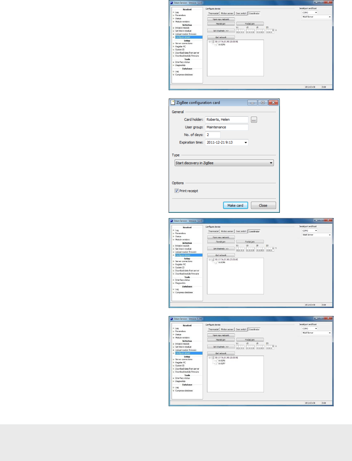
14. Click the plus sign in front of the
thermostat; the motion sensor will
appear in the network tree.
15. Right click on the thermostat to
make sure that is still says ‘yes’
at ‘Join permitted’.
16. Issue a Discovery card in VISIONLINE:
- Go to
Start/Programs/VisiOnline/
VisiOnline
and log on.
- Double click on
ZigBee configuration
under the
Cards
tab in the
navigation window.
- Browse to choose a
Card holder
and
enter the applicable
No. of days
.
- At
Type
, choose ‘Start discovery
in ZigBee’.
- If applicable, tick the checkbox
‘Print receipt’.
- Click
Make card
and present
a card at the encoder.
17. Present the Discovery card
at the lock.
18. In Orion Service,
Configure device
section: click
Get network
under the
Coordinator
tab.
19. Click the plus sign in front of the
thermostat; the lock will appear
in the network tree.
20. Mark the thermostat and click
the
Forbid join
button.
21. Right click on the thermostat
and choose
Get user description
.
Make sure that the description says
‘no’ at ‘Join permitted’.
September
1
3
, 20
12
Page
44
of
50
66 8003 00
2
-
8
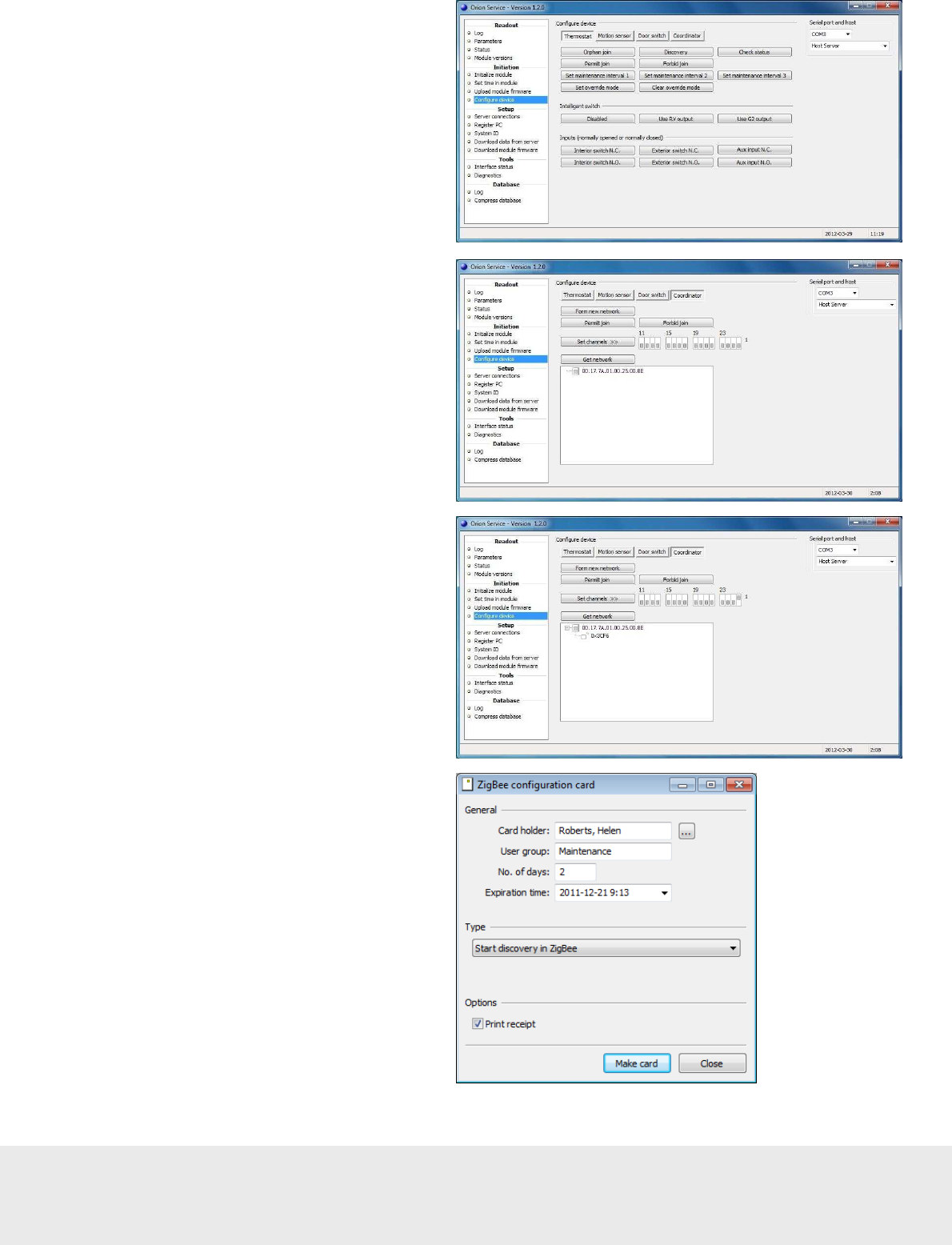
Scenario with thermostat controller and battery thermostat
1. Go to
Start/Programs/
Orion Service/Orion Service
.
2. Choose
Configure device
in the
left pane of the Orion Service window.
3. Plug the service cable into the
thermostat controller.
4. Choose the
Coordinator
tab.
5. Click
Form new network
.
6. Click the
Get network
button; the
thermostat controller will appear
in the window below
Get network
.
7. Put the cursor on the thermostat
controller in the Orion Service window;
an information box, showing e.g. the
channel for the thermostat controller,
will appear. If the channel should be
changed, click the applicable channel
(in the picture example ‘26’) and click
the
Set channels
button.
8. Mark the thermostat controller and
click the
Permit join
button.
9. Right click on the thermostat controller
and choose
Get user description
.
Information about the thermostat controller
will be shown; see picture to the right.
Make sure that
- the channel is correct
- it says ‘yes’ at
‘Join permitted’
Note:
If it does not say ‘yes’
at ‘Join permitted’, click the
Permit join
button again.
September
1
3
, 20
12
Page
45
of
50
66 8003 00
2
-
8
10. Plug the service cable
into the battery thermostat.
11. Choose the
Thermostat
tab
and click the
Discovery
button.
12. Plug the service cable
into the thermostat controller.
13. Choose the
Coordinator
tab
and click
Get network
.
14. Click the plus sign in front of the
thermostat controller; the battery
thermostat will appear in the network tree.
15. Right click on the thermostat controller
to make sure that it still says ‘yes’ at
‘Join permitted’.
16. Issue a Discovery card in VISIONLINE:
- Go to
Start/Programs/VisiOnline/
VisiOnline
and log on.
- Double click on
ZigBee configuration
under the
Cards
tab in the
navigation window.
- Browse to choose a
Card holder
and
enter the applicable
No. of days
.
- At
Type
, choose ‘Start discovery
in ZigBee’.
- If applicable, tick the checkbox
‘Print receipt’.
- Click
Make card
and present
a card at the encoder.
17. Present the Discovery card at the lock.
September
1
3
, 20
12
Page
46
of
50
66 8003 00
2
-
8
18. In Orion Service,
Configure device
section: click
Get network
under
the
Coordinator
tab.
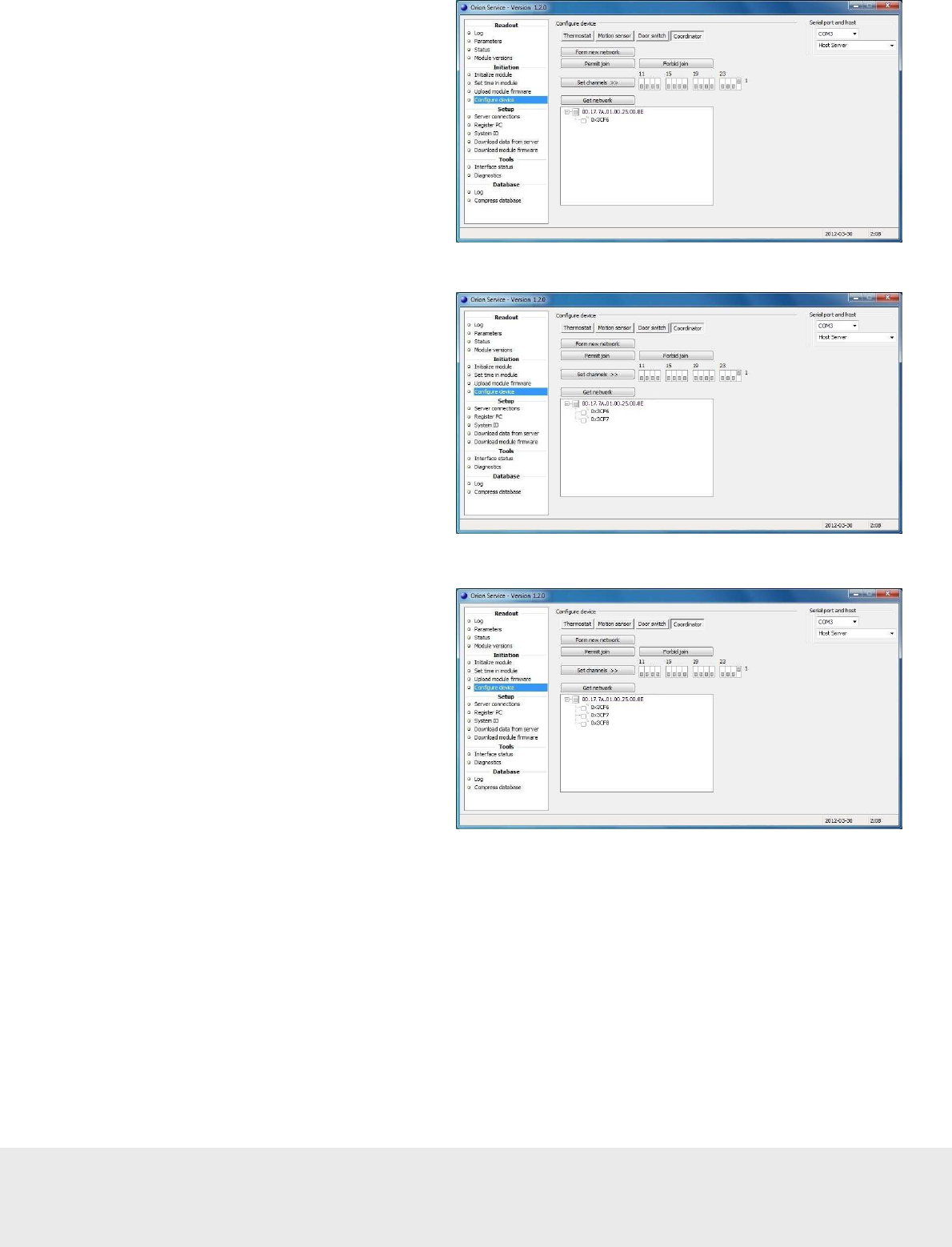
19. Click the plus sign in front of the
thermostat controller; the lock will
appear in the network tree.
20. Follow the procedure in steps 8-14
and 18-19 to add the motion sensor
to the in-room network.
21. Mark the thermostat controller
in the Orion Service window
and click the
Forbid join
button.
22. Right click on the thermostat controller
and choose
Get user description
.
Make sure that the description says
‘no’ at ‘Join permitted’.
September
1
3
, 20
12
Page
47
of
50
66 8003 00
2
-
8
Enabling EMI events
There are two ways to enable that EMI events are sent from the lock:
•
by presenting an Enable EMI events card at the lock; see section Enabling EMI events via card.
•
by enabling EMI events from Lock Service; see section Enabling EMI events via Lock Service.
For more details about using Lock Service, see Quick reference guide Service PC.
Note: Both ways require that the Online option has been set in VISIONLINE.
See Setup manual VingCard VISIONLINE for information on how to set an option.
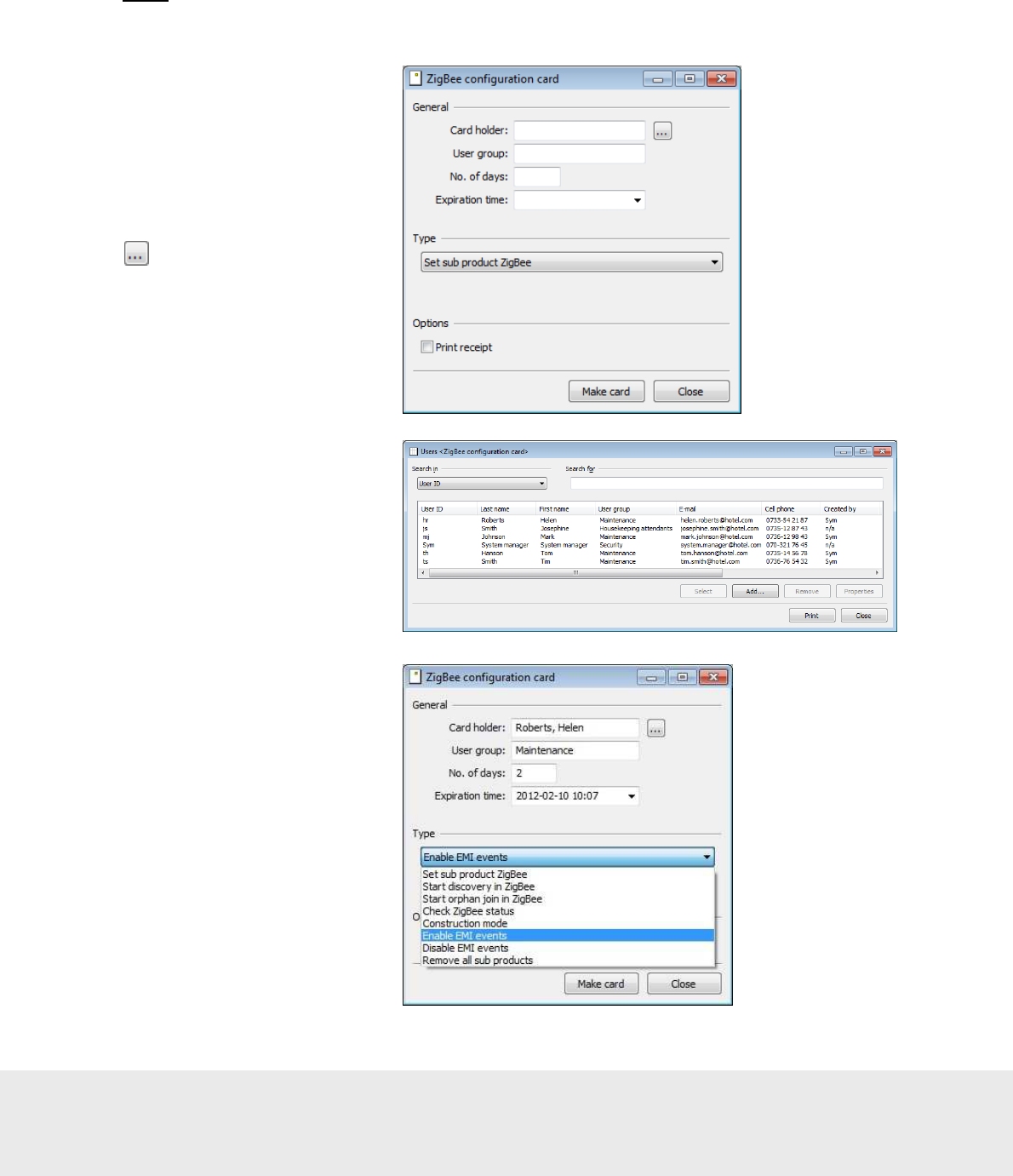
Enabling EMI events via card
1. Go to
Start/Programs/
VisiOnline/VisiOnline
and log on.
2. Double click on
ZigBee
configuration
under
the
Cards
tab in the
navigation window.
3. At
Card holder
, click the
4. In the
Users <ZigBee
configuration card>
dialog,
mark the applicable user
and click
Select
.
5. The
Card holder
and also the
User
group
will appear in the
ZigBee
configuration card
dialog.
6. Enter the
No. of days
; the
Expiration time
will
automatically fill in.
7. At
Type
, choose ‘Enable EMI
events’ in the drop-down-menu.
8. If applicable, tick the checkbox
Print receipt
.
9. Click
Make card
.
10. Present a card at the encoder.
11. Present the Enable EMI events
card at the lock.
button.
September
1
3
, 20
12
Page
48
of
50
66 8003 00
2
-
8
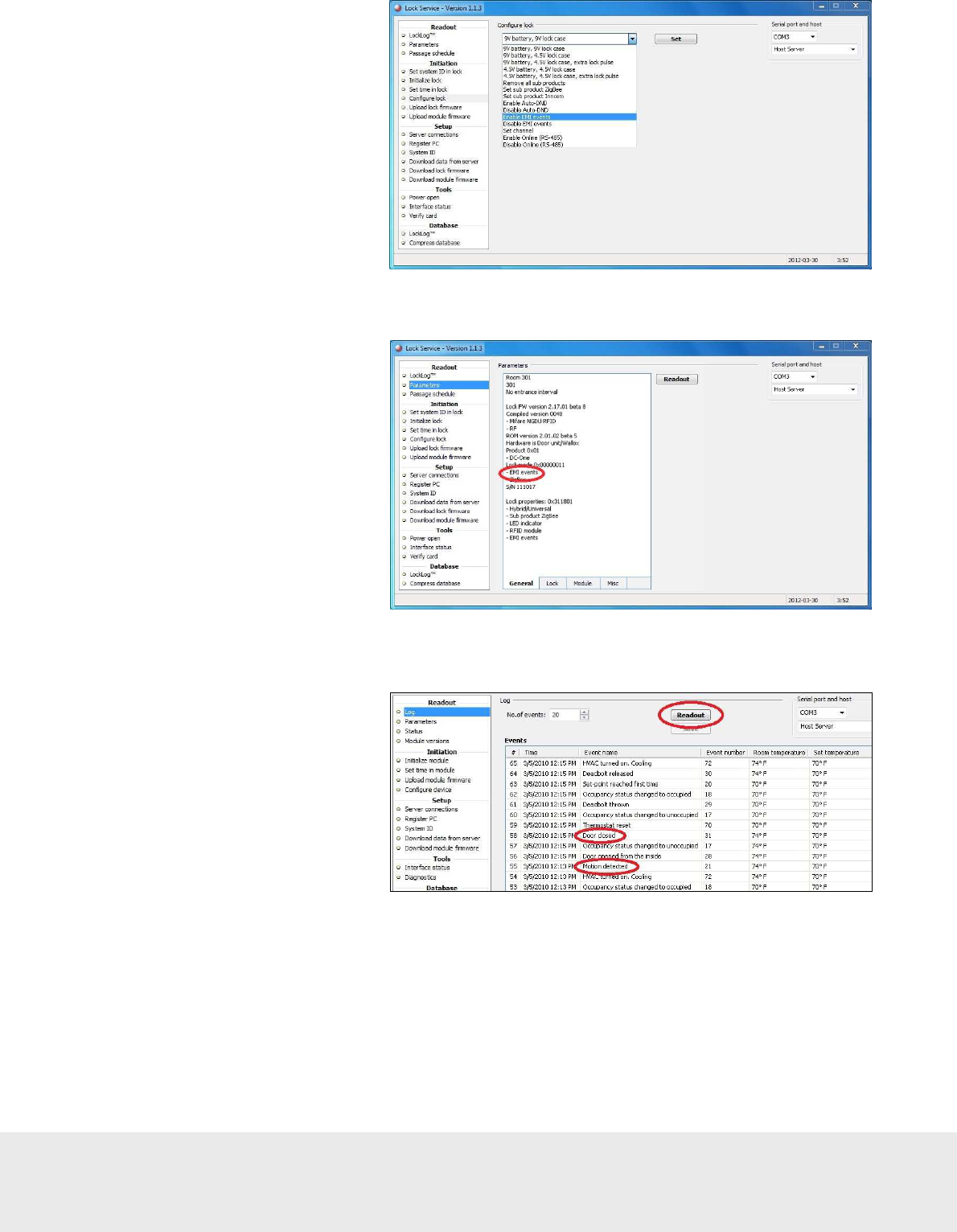
Enabling EMI events via Lock Service
1. Go to
Start/Programs/
Lock Service/Lock Service
.
2. Choose
Configure lock
in the left pane of the
Lock Service window.
3. In the drop-down-menu,
choose ‘Enable EMI events’.
4. Plug the applicable service cable
into the lock (may be another
service cable than 205 999 005
depending on lock type) and click
the
Set
button in Lock Service.
Checking EMI events in Lock Service
1. Choose
Parameters
in the left pane
of the Lock Service window.
2. Make sure that ‘EMI events’ is
shown under the
General
tab.
Logging EMI events in Orion Service
If desired:
1. Provoke some EMI events in
the lock, e.g. ‘Door closed’
and ‘Motion detected’.
2. Go to
Start/Programs/
Orion Service/Orion Service
.
3. Choose
Log
under the
Readout
section in the left pane; choose
the applicable
No. of events
.
4. Plug the service cable into
either the wired thermostat
or the thermostat controller,
depending on configuration.
5. Click the
Readout
button in
Orion Service.
6. Ensure that the door and motion
events (e.g. ‘Door closed’ and
‘Motion detected’) are logged as
in the example picture to the right.

September
1
3
, 20
12
Page
49
of
50
66 8003 00
2
-
8
Revision history
Date Change By
August 19, 2010 Initial version KG
November 15, 2010 ‘Configure device’ in Orion Service modified KG
July 5, 2011 • Information about thermostat controller added
• Information about service indicators added
• Appendix about Orion Service connections added
• Appendix about configuration in offline scenarios added
KG
October 6, 2011 • Logotypes changed
• Information about commissioning when thermostat controller is
used has been added
KG
October 20, 2011 • Section about Recommended wire specification modified due to
requirements for UL certification
• Picture in section Line to low voltage conversion exchanged
due to requirements for UL certification
KG
February 16, 2012 • Added reference to Upgrading an RFID lock for an Orion EMS
offline scenario for information about what firmware to use in
different configurations
• Added information about RF door switch
• Modified the section Commissioning the system; use the
Thermostat
tab also for battery thermostats
• Added information to Appendix C: Configuration in
offline scenario:
- configuration pictures
- how to enable and log EMI events in locks
KG
June 5, 2012 • Updated to match Orion Service 1.2.0 KG
July 5, 2012
•
Info added to chapter 1 General about the number of Orion EMS
devices that each room number can have a certain number of
Orion EMS devices
KG
September 13, 2012
•
Clarified about V+ in section 3.3
•
Clarified about V+ and signal inputs in section 4.1
•
Added section 4.1.1 about RS-485 interface
•
Removed information about USB Xpress in Appendix A
KG

Asia / Pacific:
Europe / Middle East / Africa:
E-mail: aspac@vcegroup.com E-mail: emea@vcegroup.com
Phone: +65 67 48 7 227 Phone: +47 69 24 50 00
Latin America: North America:
E-mail: lam@vcegroup.com E-mail: noram@vcegroup.com
Phone: +52 55 36 40 12 14 Phone: +1 972 907 2273
VingCard Elsafe – P.O. Box 511 – 1522 Moss – Norway – Phone: +47 69 24 50 00
info@vcegroup.com | www.vingcardelsafe.com
Provider of: VingCard Locks & Systems | Elsafe Safes | Orion EMS | PolarBar Minibars
Specifications may change without notice
FCC STATEMENT
1. This device complies with Part 15 of the FCC Rules. Operation is subject to the
following two conditions:
(1) This device may not cause harmful interference.
(2) This device must accept any interference received, including interference that may
cause undesired operation.
Changes or modifications not expressly approved by the party responsible for compliance
could void the user's authority to operate the equipment.
NOTE: This equipment has been tested and found to comply with the limits for a Class B
digital device, pursuant to Part 15 of the FCC Rules. These limits are designed to provide
reasonable protection against harmful interference in a residential installation.
This equipment generates uses and can radiate radio frequency energy and, if not
installed and used in accordance with the instructions, may cause harmful interference to
radio communications. However, there is no guarantee that interference will not occur in a
particular installation. If this equipment does cause harmful interference to radio or
television reception, which can be determined by turning the equipment off and on, the
user is encouraged to try to correct the interference by one or more of the following
measures:
Reorient or relocate the receiving antenna.
Increase the separation between the equipment and receiver.
Connect the equipment into an outlet on a circuit different from that to which the
receiver is connected.
Consult the dealer or an experienced radio/TV technician for help.