COMPUTIME CT-EM2503 ZigBee Module User Manual CT EM2503
Computime Limited ZigBee Module CT EM2503
UserManual.wiki
>
COMPUTIME
>
CT EM2503 User Manual
User Manual
Navigation menu
Upload a User Manual
Namespaces
Wiki Guide
HTML
PDF
Info
Views
User Manual
Discussion / Help
Navigation
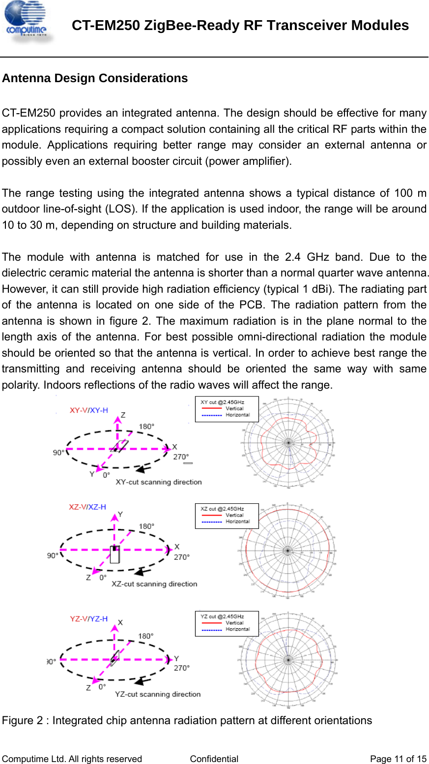
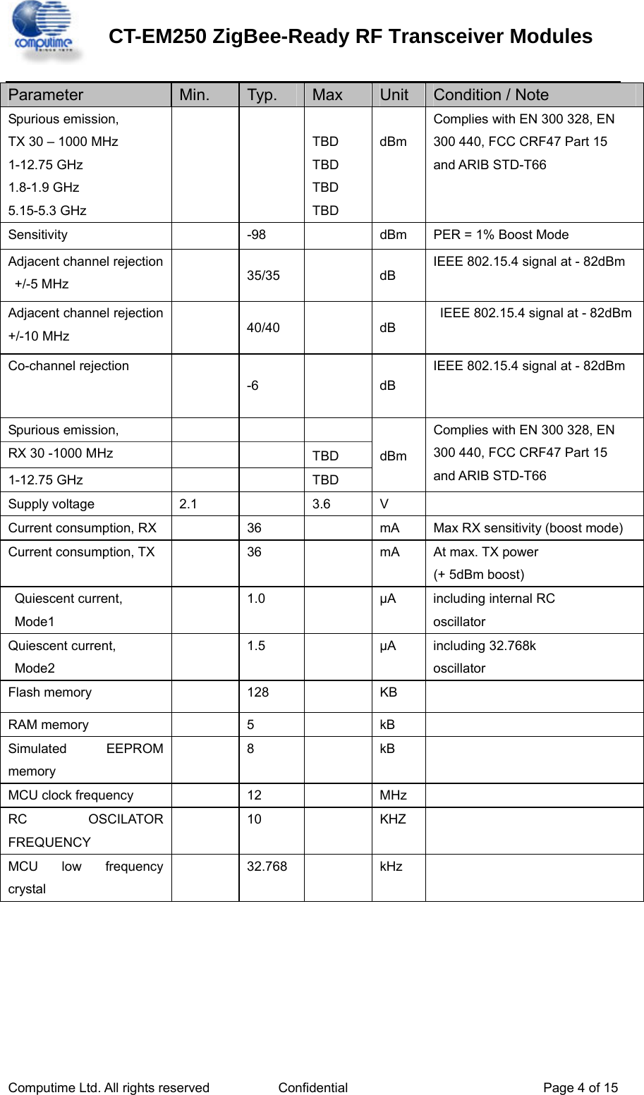
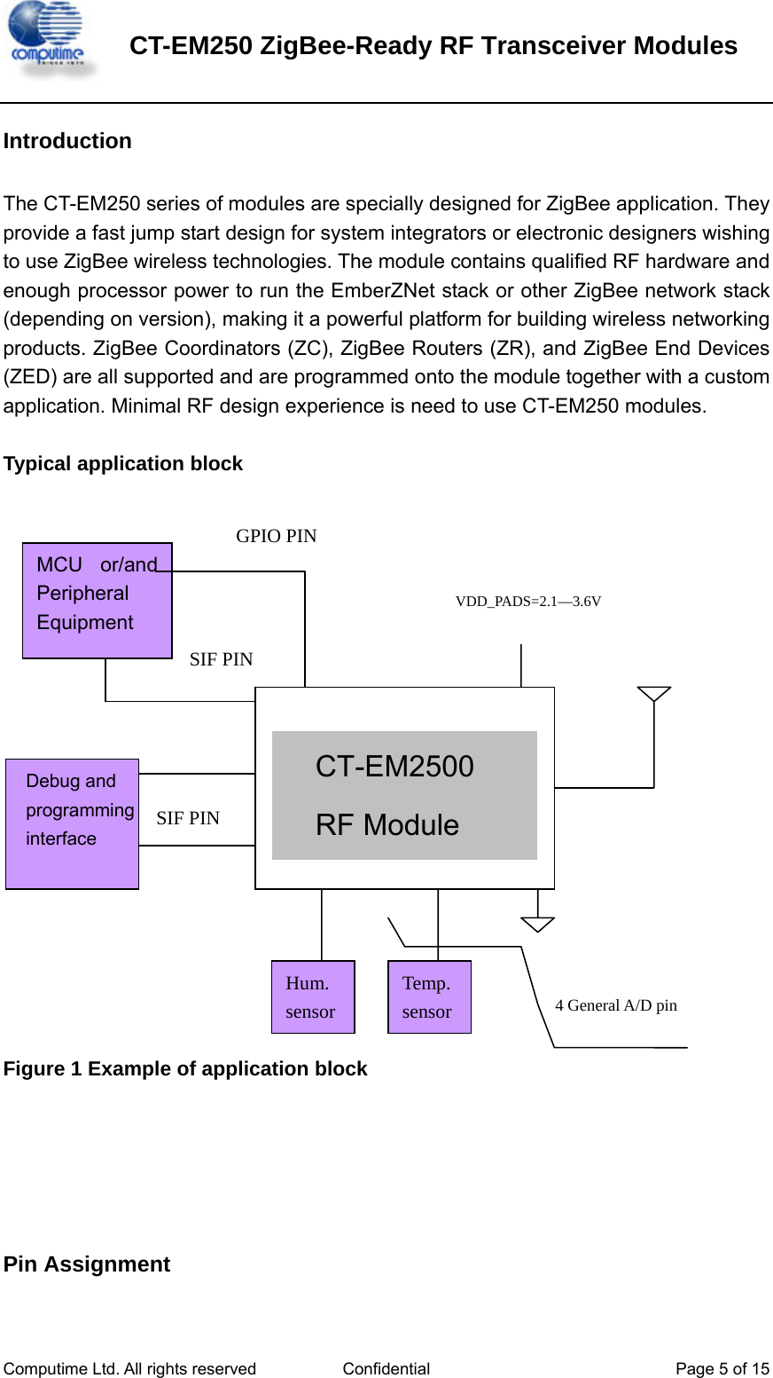
![CT-EM250 ZigBee-Ready RF Transceiver Modules Computime Ltd. All rights reserved Confidential Page 3 of 15 Absolute Maximum Ratings Parameter Test Conditions Min. Max. Unit Regulator voltage (VDD_PADS) - 0.3 3.6 V Voltage on any GPIO[16:0], SIF_CLK, SIF_MISO, SIF_MOSI, nSIF_LOAD, OSC32A, OSC32B, nRESET, - 0.3 VDD_PADS+ 0.3 V Storage temperature - 40 + 140 °C Under no circumstances should the absolute maximum ratings given above be violated. Stress exceeding one or more of the limiting values may cause permanent damage to the device. Recommended Operating Conditions Parameter Test Conditions Min. Typ. Max. Unit Regulator input voltage (VDD_PADS) 2.1 3.6 V Core input voltage (VDD_24MHZ, VDD_VCO, VDD_RF, VDD_IF, VDD_PADSA, VDD_FLASH, VDD_PRE, VDD_SYNTH, VDD_CORE) 1.7 1.8 1.9 V Temperature range - 40 + 85 °C Electrical Specifications T=25 ℃, VCC = 3.0V, fo=2450Mhz, if nothing else stated. Parameter Min. Typ. Max Unit Condition / Note Operating frequency 2405 2480 M Programmable in 5 MHz steps for IEEE 802.15.4 compliance Number of channels 16 For IEEE 802.15.4 compliance Channel spacing 5 MHz For IEEE 802.15.4 compliance Input/output impedance 50 Ohm Data rate 250 kbit/s DSSS chip rate 2 Mc/s Frequency stability +/-40 ppm Transmit power -32 5 dBm Programmable from firmware Harmonics 2nd harmonic TBD dBm 3rd harmonic TBD dBm](https://usermanual.wiki/COMPUTIME/CT-EM2503/User-Guide-800970-Page-3.png)
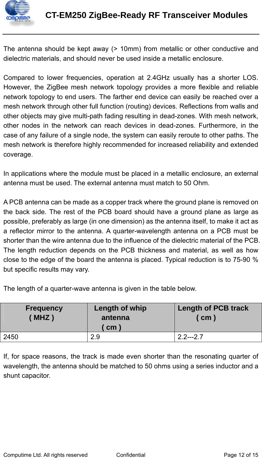
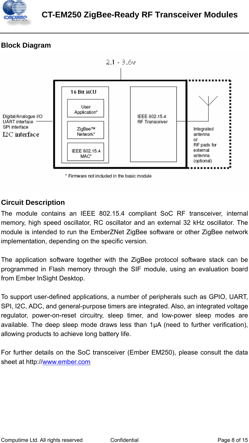
![CT-EM250 ZigBee-Ready RF Transceiver Modules Computime Ltd. All rights reserved Confidential Page 6 of 15 Pin Description Pin# Signal Direction Description 1 SIF_MISO O Serial interface, master in/slave out 2 SIF_MOSI I Serial interface, master out/slave in 3 SIF_LOADB I/O Serial interface, load strobe (open-collector with internal pull-up) 4 GND Ground Ground supply 5 GPIO16 I/O Digital I/O Enable GPIO16 with GPIO_CFG[3] 6 GPIO15 I/O Digital I/O Enable GPIO15 with GPIO_CFG[2] 7 GPIO14 I/O Digital I/O Enable GPIO14 with GPIO_CFG[1] 8 GPIO13 I/O Digital I/O Enable GPIO13 with GPIO_CFG[0] 9 GND Ground Ground supply 10 GND Ground Ground supply 11 ANT I/O receiver input/transmitter output 12 GND Ground Ground supply 13 nRESET I Active low chip reset (internal pull-up) 14 OSCB I/O 24MHz crystal oscillator or left open when using external clock input on OSCA 15 OSCA I/O 24MHz crystal oscillator or external clock input 16 VBRD Power Pads supply (2.1-3.6V) 17 GPIO11 I/O Digital I/O Enable GPIO11 with GPIO_CFG[7:4] 18 GPIO12 I/O Digital I/O Enable GPIO12 with GPIO_CFG[7:4] 19 GPIO0 I/O Digital I/O Enable GPIO0 with GPIO_CFG[7:4] 20 GPIO1 I/O Digital I/O Enable GPIO1 with GPIO_CFG[7:4] 21 GPIO2 I/O Digital I/O](https://usermanual.wiki/COMPUTIME/CT-EM2503/User-Guide-800970-Page-6.png)
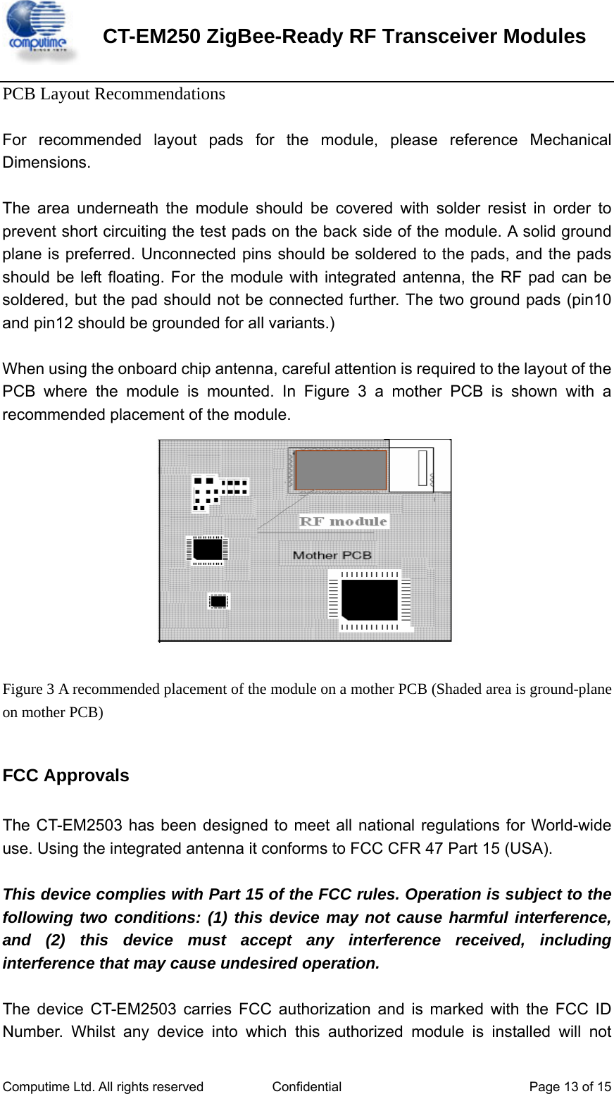
![CT-EM250 ZigBee-Ready RF Transceiver Modules Computime Ltd. All rights reserved Confidential Page 7 of 15 Enable GPIO2 with GPIO_CFG[7:4] 22 GPIO3 I/O Digital I/O Enable GPIO3 with GPIO_CFG[7:4] 23 GPIO4 I/O Digital I/O Enable GPIO4 with GPIO_CFG[12] and GPIO_CFG[8] 24 GPIO5 I/O Digital I/O Enable GPIO5 with GPIO_CFG[12] and GPIO_CFG[9] 25 GPIO6 I/O Digital I/O Enable GPIO6 with GPIO_CFG[10] 26 GPIO7 I/O Digital I/O Enable GPIO7 with GPIO_CFG[13] and GPIO_CFG[11] 27 GPIO8 I/O Digital I/O Enable GPIO8 with GPIO_CFG[14] 28 TXD O UART transmit data of Serial Controller SC1 Enable SC1-4A or SC1-2 with GPIO_CFG[7:4], select UART with SC1_MODE 29 RXD I UART receive data of Serial Controller SC1 Enable SC1-4A or SC1-2 with GPIO_CFG[7:4], select UART with SC1_MODE 30 SIF_CLK I Serial interface, clock (internal pull-down)](https://usermanual.wiki/COMPUTIME/CT-EM2503/User-Guide-800970-Page-7.png)
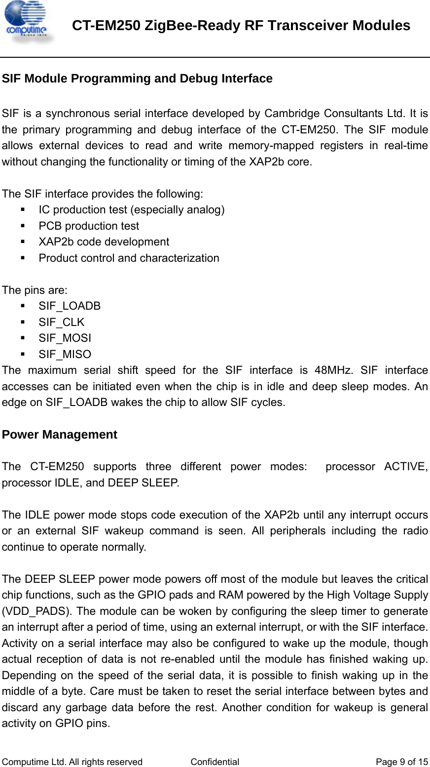
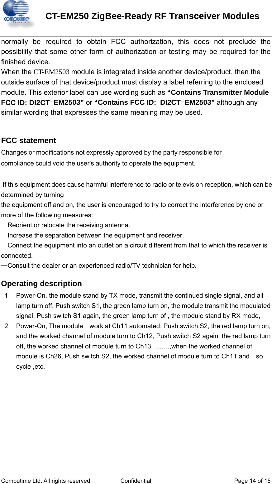
![CT-EM250 ZigBee-Ready RF Transceiver Modules Computime Ltd. All rights reserved Confidential Page 10 of 15 RF Frequency, Output Power Levels and Data Rates The following table shows the RF channels as defined by the IEEE 802.15.4 The output power level can be configured in the range -32 to 5 dBm. The RF transceiver uses direct sequence spread spectrum (DSSS) with a raw data rate of 250 kbit/s. The modulation format is Offset – Quadrature Phase Shift Keying (O-QPSK). It is robust even under noisy environments when sharing the same frequency band with other applications. The use of RF frequencies and maximum allowed RF power should according to different national regulations. The CT-EM250 is complying with the applicable regulations for the world wide 2.4GHz ISM band. [Subject to final approval: Specifically it complies with the European Union R&TTE directive meeting EN 300 328 and EN300 440 class 2. It also meets the FCC CFR47 Part15 regulations for use in the US and the ARIB T-66 for use in Japan.]](https://usermanual.wiki/COMPUTIME/CT-EM2503/User-Guide-800970-Page-10.png)