Computime CT-EM2506 ZigBee Module User Manual CT EM2506 V1 2
Computime Limited ZigBee Module CT EM2506 V1 2
User Manual

CT-EM2506 ZigBee Ready RF Transceiver Modules
Computime Ltd. All rights reserved Confidential Page 1 of 16
ZigBee- Ready SoC RF Transceiver Modules
CT- EM2506 Series Specification

CT-EM2506 ZigBee Ready RF Transceiver Modules
Computime Ltd. All rights reserved Confidential Page 2 of 16
Table of Content
1. General Description ..................................................................................................................3
2. Applications..............................................................................................................................3
3. Features.....................................................................................................................................3
4. Absolute Maximum Ratings .....................................................................................................4
5. Recommended Operating Conditions .......................................................................................4
6. Electrical Specifications............................................................................................................4
7. Introduction...............................................................................................................................6
8. Typical application block..........................................................................................................6
9. Pin Assignment .........................................................................................................................7
10. Pin Description......................................................................................................................7
11. Block Diagram......................................................................................................................9
12. Circuit Description................................................................................................................9
13. SIF Module Programming and Debug Interface.................................................................10
14. Power Management.............................................................................................................10
15. RF Frequency, Output Power Levels and Data Rates .........................................................11
16. Antenna Design Considerations..........................................................................................12
17. Product Approvals...............................................................................................................13
18 Mechanical Dimension .......................................................................................................15
19 Ordering Information..........................................................................................................16
20 Document Revision History................................................................................................16

CT-EM2506 ZigBee Ready RF Transceiver Modules
Computime Ltd. All rights reserved Confidential Page 3 of 16
ZigBee- Ready SoC RF Transceiver Modules
1. General Description
The CT-EM2506 SoC RF Transceiver Modules is a compact surface mounted
module specially designed for Ember’s ZigBee™ protocol stack for wireless networks,
EmberZNet, based on IEEE 802.15.4 standard in the 2.4GHz world-wide ISM band. It
provides 16 channels and compliant PHY and MAC layers. The complete module is
only 25.4 x 32.4 x 4.1mm. They both integrate a 2.4GHz, IEEE 802.15.4-compliant
transceiver with a 16-bit XAP2b microprocessor and a FEM. They consist of
integrated Flash and RAM memory and peripherals. A number of peripherals such as
GPIO, UART, SPI, I2C, ADC, and general purpose timers are integrated to support
user-defined applications.
2. Applications
Home
automation &
building control
Home
appliances &
alarms
Monitoring of
remote
systems
Lighting
controls
Sensor data
capturing
3. Features
Integrated PCB trace antenna
IEEE 802.15.4 compliant PHY and MAC layer
12MHz XAP2b 16-bit microcontroller core
128kB Flash and 5kB RAM, emulation EEPROM
17 GPIO , 4 channel 12 bit ADC
UART, SPI, I2C and debug interfaces
External 32.768 kHz real time clock or internal RC oscillator for timer
16 channels in the 2.4 GHz ISM band
On-chip regulator for 2.7-3.6V operation, three sleep low power modes
-15dBm------20dBm output power, SW controlled

CT-EM2506 ZigBee Ready RF Transceiver Modules
Computime Ltd. All rights reserved Confidential Page 4 of 16
4. Absolute Maximum Ratings
Parameter Test Conditions Min. Max. Unit
Regulator voltage (VDD_PADS) - 0.3 3.6 V
Voltage on any GPIO[16:0], SIF_CLK,
SIF_MISO, SIF_MOSI, nSIF_LOAD, OSC32A,
OSC32B, nRESET
- 0.3 VDD_PADS+
0.3
V
Storage temperature - 40 + 140 °C
Under no circumstances should the absolute maximum ratings given above be violated. Stress exceeding
one or more of the limiting values may cause permanent damage to the device.
5. Recommended Operating Conditions
Parameter Test Conditions Min. Typ. Max. Unit
Regulator input voltage (VDD_PADS) 2.7 3.6
Core input voltage (VDD_24MHZ, VDD_VCO,
VDD_RF, VDD_IF, VDD_PADSA,
VDD_FLASH, VDD_PRE, VDD_SYNTH,
VDD_CORE)
1.7 1.8 1.9 V
Temperature range - 40 + 85 °C
6. Electrical Specifications
T = 25℃, VCC = 3.0V, fo = 2450Mhz, if nothing else stated.
Parameter Min. Typ. Max Unit Condition / Note
Operating frequency 2400 2483.5 MHz Programmable in 5 MHz steps for
IEEE 802.15.4 compliance
Number of channels 16 For IEEE 802.15.4 compliance
Channel spacing 5 MHz For IEEE 802.15.4 compliance
Input/output impedance 50 Ohm
Data rate 250 kbit/s
DSSS chip rate 2 Mc/s
Frequency stability +/-40 ppm
Transmit power -15 20 dBm Programmable from software

CT-EM2506 ZigBee Ready RF Transceiver Modules
Computime Ltd. All rights reserved Confidential Page 5 of 16
Parameter Min. Typ. Max Unit Condition / Note
Sensitivity -98 dBm PER = 1% Boost Mode
Adjacent channel rejection
+/-5 MHz 35/35 dB
IEEE 802.15.4 signal at - 82dBm
Adjacent channel rejection
+/-10 MHz 40/40 dB
IEEE 802.15.4 signal at -
82dBm
Co-channel rejection -6 dB IEEE 802.15.4 signal at - 82dBm
Supply voltage 2.7 3.6 V
36 mA Max RX sensitivity (normal mode)
Current consumption
RX mode 38 mA Max RX sensitivity (boost mode)
Current consumption
TX Mode 190 mA 20dBm output
Quiescent current 5.0 μA
Flash memory 128 KB
RAM memory 5 KB
Simulated EEPROM memory 8 KB
MCU clock frequency 12 MHz
RC OSCILATOR frequency 10 KHZ
MCU low frequency crystal 32.768 kHz
CT-EM2506 ZigBee Ready RF Transceiver Modules
Computime Ltd. All rights reserved Confidential Page 6 of 16
7. Introduction
The CT-EM2506 series of modules are specially designed for ZigBee application. They
provide a fast jump start design for system integrators or electronic designers wishing to
use ZigBee wireless technologies. The module contains qualified RF hardware and
enough processor power to run the EmberZNet stack or other ZigBee network stack
(depending on version), making it a powerful platform for building wireless networking
products. ZigBee Coordinators (ZC), ZigBee Routers (ZR), and ZigBee End Devices
(ZED) are all supported and are programmed onto the module together with a custom
application. Minimal RF design experience is needed to use CT-EM2506 modules.
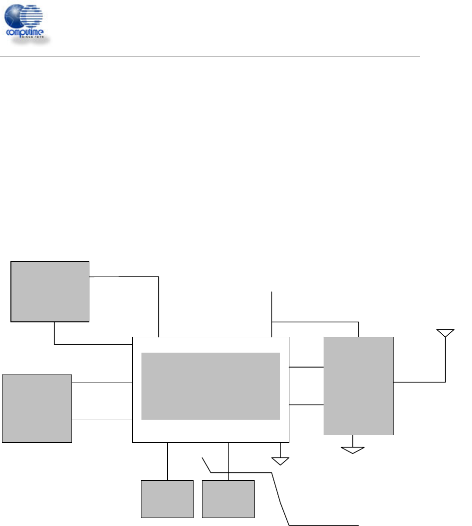
8. Typical application block
Ember
EM250
Temp.
Sensor
Hum.
Sensor
VDD_PADS=2.7-3.6V
4 General A/D
Debug and
programming
interface SIF PIN
MCU and/or
Peripheral
Equipment
SIF PIN
GPIO PIN
FEM
CT-EM2506 ZigBee Ready RF Transceiver Modules
Computime Ltd. All rights reserved Confidential Page 7 of 16
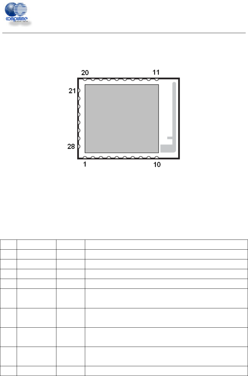
9. Pin Assignment
TOP VIEW
10. Pin Description
Pin# Signal Direction Description
1 CLK DI SIF Interface clock
2 MISO DO SIF Interface master in/slave out
3 MOSI DI SIF Interface master out/slave in
4 LOADB DI/DO SIF Interface load strobe
5 GPIO16 DI/DO
General Purpose Digital I/O, Output B of Timer 1, Capture Input B of
Timer 2, or Source D Interrupt
6 GPIO15 DI/DO
General Purpose Digital I/O, Output A of Timer 1, Capture Input A of
Timer 2, or Source C Interrupt
7 GPIO14 DI/DO
General Purpose Digital I/O, Output B of Timer 2, Capture Input B of
Timer 1, or Source B Interrupt
8 GPIO13 DI/DO
General Purpose Digital I/O, Output A of Timer 2, or Capture Input A of
Timer 1
9 GROUND GND Ground

CT-EM2506 ZigBee Ready RF Transceiver Modules
Computime Ltd. All rights reserved Confidential Page 8 of 16
10 GROUND GND Ground
11 GROUND GND Ground
12 GROUND GND Ground
13 IDLE_EN I
Enable the FEM in deep sleep mode , Active high, in other state, set it
in low level
14 VBRD PI Power Supply Input
15 RSTB DI Reset, active low
16 GPIO11 DI/DO
General Purpose Digital I/O, SC1 UART CTS, SC1 SPI master clock,
or Capture Input A of Timer 2
17 GPIO12 DI/DO
General Purpose Digital I/O, SC1 UART RTS, or Capture Input B of
Timer 2
18 GPIO0 DI/DO
General Purpose Digital I/O, SC2 SPI MOSI, or Capture Input A of
Timer 1
19 GPIO1 DI/DO
General Purpose Digital I/O, SC2 SPI MISO, SC2 I2C SDA,
or Capture Input A of Timer 2
20 GPIO2 DI/DO
General Purpose Digital I/O, SC2 SPI master clock, SC2 I2C SCL, or
Capture Input B of Timer 2
21 GPIO3 DI/DO
General Purpose Digital I/O, SC2 SPI slave select, or Capture Input B
of Timer 1
22 GPIO4 DI/DO/AI General Purpose Digital I/O, ADC Input 0, or PTI frame signal
23 GPIO5 DI/DO/AI General Purpose Digital I/O, ADC Input 1, or PTI data signal
24 GPIO6 DI/DO/AI
General Purpose Digital I/O, ADC Input 2, Timer 2 Clock Input, or
Timer 1 Enable
25 GPIO7 DI/DO/AI
General Purpose Digital I/O, ADC Input 3, Timer 2 Clock Input,
External regulator open collector output
26 GPIO8 DI/DO/AO
General Purpose Digital I/O, ADC Reference Output, Timer 1 Clock
Input, Timer 2 Enable, or Source A Interrupt
27 GPIO9 DI/DO
General Purpose Digital I/O, SC1 TXD, SC1 MO, SC1 I2C Data,
or Capture Input A of Timer 1
28 GPIO10 DI/DO
General Purpose Digital I/O, SC1 RXD, SC1 MI, SC1 I2C Clock,
or Capture Input B of Timer 1
CT-EM2506 ZigBee Ready RF Transceiver Modules
Computime Ltd. All rights reserved Confidential Page 9 of 16
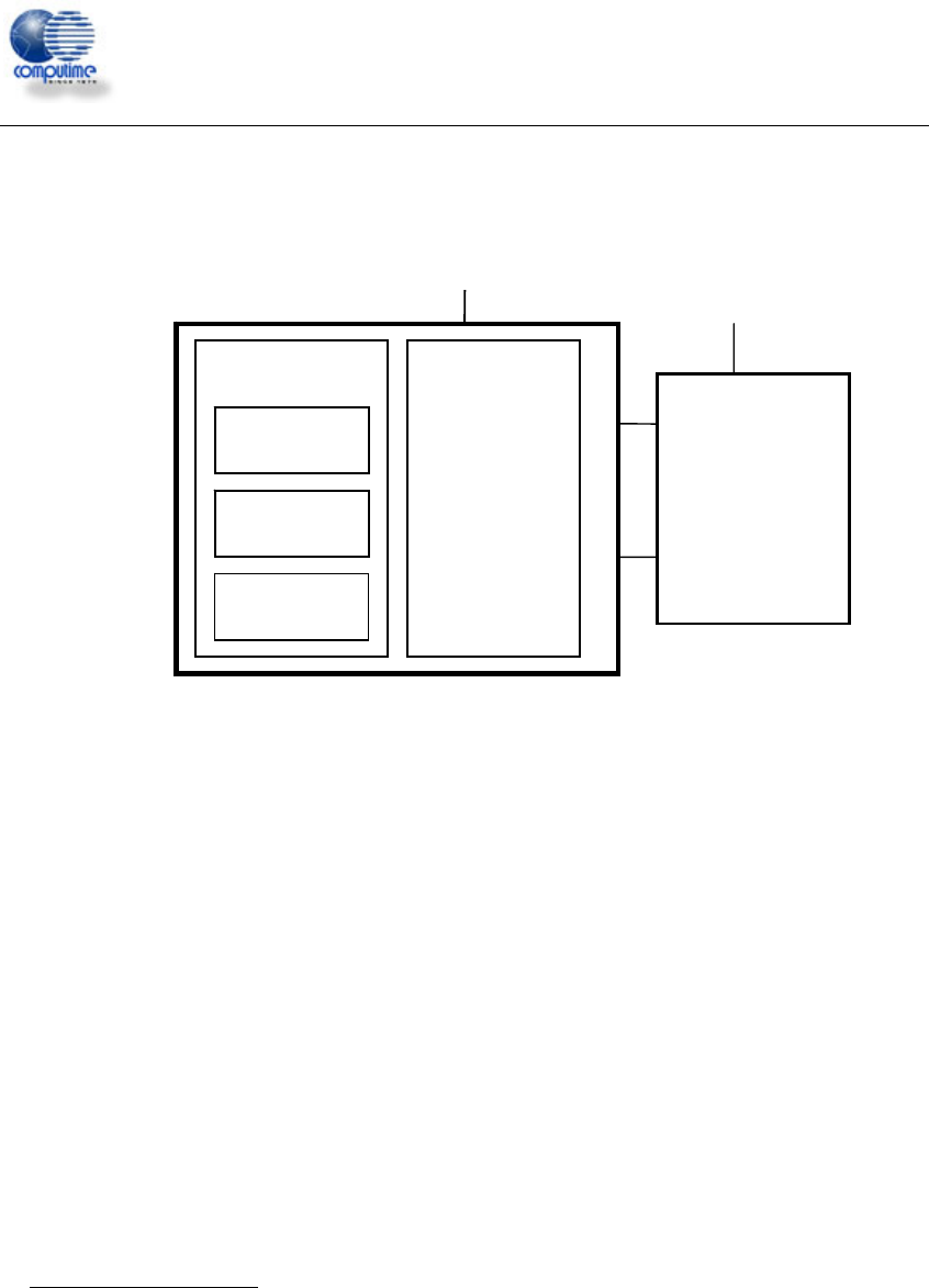
11. Block Diagram
12. Circuit Description
The module contains an IEEE 802.15.4 compliant SoC RF transceiver, internal memory,
high speed oscillator, RC oscillator, an FEM . The module is intended to run the
EmberZNet ZigBee software or other ZigBee network implementation, depending on the
specific version.
The application software together with the ZigBee protocol software stack can be
programmed in Flash memory through the SIF module, using an evaluation board from
Ember InSight Desktop.
To support user-defined applications, a number of peripherals such as GPIO, UART, SPI,
I2C, ADC, and general-purpose timers are integrated. Also, an integrated voltage
regulator, power-on-reset circuitry, sleep timer, and low-power sleep modes are available.
The deep sleep mode draws less than 5μA , allowing products to achieve long battery life.
For further details on the SoC transceiver (Ember EM250), please consult the data sheet
at http://www.ember.com
Digital/Analog I/O
UART interface
SPI interface
I2C interface
16 Bit MCU
User
Application
Zigbee
TM
Network
IEEE 802.15.4
MAC
IEEE 802.15.4
RF Transceiver
2.7 – 3.6V 2.7 – 3.6V
RF Frond End

CT-EM2506 ZigBee Ready RF Transceiver Modules
Computime Ltd. All rights reserved Confidential Page 10 of 16
13. SIF Module Programming and Debug Interface
SIF is a synchronous serial interface developed by Cambridge Consultants Ltd. It is the
primary programming and debug interface of the CT-EM2506. The SIF module allows
external devices to read and write memory-mapped registers in real-time without
changing the functionality or timing of the XAP2b core.
The SIF interface provides the following:
IC production test (especially analog)
PCB production test
XAP2b code development
Product control and characterization
The pins are:
SIF_LOADB
SIF_CLK
SIF_MOSI
SIF_MISO
The maximum serial shift speed for the SIF interface is 48MHz. SIF interface accesses
can be initiated even when the chip is in idle and deep sleep modes. An edge on
SIF_LOADB wakes the chip to allow SIF cycles.
14. Power Management
The CT-EM2506 supports three different power modes: processor ACTIVE, processor
IDLE and DEEP SLEEP.
The IDLE power mode stops code execution of the XAP2b until any interrupt occurs or an
external SIF wakeup command is seen. All peripherals including the radio continue to
operate normally.
The DEEP SLEEP power mode powers off most of the module but leaves the critical chip functions,
such as the GPIO pads and RAM powered by the High Voltage Supply (VDD_PADS). The module
can be woken by configuring the sleep timer to generate an interrupt after a period of time, using an
external interrupt, or with the SIF interface. Activity on a serial interface may also be configured to
wake up the module, though actual reception of data is not re-enabled until the module has finished
waking up. Depending on the speed of the serial data, it is possible to finish waking up in the middle
of a byte. Care must be taken to reset the serial interface between bytes and discard any garbage data
before the rest. Another condition for wakeup is general activity on GPIO pins.

CT-EM2506 ZigBee Ready RF Transceiver Modules
Computime Ltd. All rights reserved Confidential Page 11 of 16
15. RF Frequency, Output Power Levels and Data Rates
The following table shows the RF channels as defined by the IEEE 802.15.4
RF channel Frequency
11 2405MHz
12 2410MHz
13 2415MHz
14 2420MHz
15 2425MHz
16 2430MHz
17 2435MHz
18 2440MHz
19 2445MHz
20 2450MHz
21 2455MHz
22 2460MHz
23 2465MHz
24 2470MHz
25 2475MHz
26 2480MHz
The output power level of EM250 can be configured in the range -32 to 3dBm and the
gain of FEM is 17dB, So the module output can controlled in range -15 to 20dBm. The RF
transceiver uses direct sequence spread spectrum (DSSS) with a raw data rate of 250
kbit/s. The modulation format is Offset – Quadrature Phase Shift Keying (O-QPSK). It is
robust even under noisy environments when sharing the same frequency band with other
applications.
Note: The output power of EM250 should be configured lower than -19dBm for
the channel 2480MHz to comply FCC.
The use of RF frequencies and maximum allowed RF power should according to different
national regulations. The CT-EM2506 is complying with the applicable regulations for the
world wide 2.4GHz ISM band.
[Subject to final approval: Specifically it complies with the European Union R&TTE directive
meeting EN 300 328 and EN300 440 class 2. It also meets the FCC CFR47 Part15 regulations for use
in the US and the ARIB T-66 for use in Japan.]
CT-EM2506 ZigBee Ready RF Transceiver Modules
Computime Ltd. All rights reserved Confidential Page 12 of 16
16. Antenna Design Considerations
The CT-EM2506 module includes an integrated PCB trace antenna. An optional MMCX
connector can be specified, enabling connection to a 50-ohm external antenna of the user’s
choice..
The PCB antenna employs an F-Antenna topology that is compact and supports an
omni-directional radiation pattern. To maximize antenna efficiency, an adequate ground
plane must be provided on the host PCB. If positioned correctly, the ground plane on the host
board under the module can contribute significantly to antenna performance.
The position of the module on the host board and overall design of the product enclosure
contribute to antenna performance. Poor design effects radiation patterns and can result in
reflection, diffraction, and/or scattering of the transmitted signal.
Here are some design guidelines to help ensure antenna performance:
• Never place the ground plane or route copper traces directly underneath the antenna
portion of the module.
• Never place the antenna close to metallic objects.
• In the overall design, ensure that wiring and other components are not placed near the
antenna.
• Do not place the antenna in a metallic or metallized plastic enclosure.
• Keep plastic enclosures 1cm or more from the antenna in any direction.
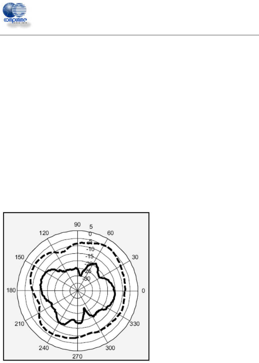
Test at 2440MHZ
__ Vertical Polarization Gain
(dBi)
Avg : -14.8
--- Horizontal Polarization Gain
(dBi)
Avg : -3.4

CT-EM2506 ZigBee Ready RF Transceiver Modules
Computime Ltd. All rights reserved Confidential Page 13 of 16
17. Product Approvals
17.1 FCC Approvals
The CT-EM2506 has been designed to meet all national regulations for World-wide use.
Using the integrated antenna it conforms to FCC CFR 47 Part 15 (USA).
This device complies with Part 15 of the FCC rules. Operation is subject to the
following two conditions: (1) this device may not cause harmful interference, and
(2) this device must accept any interference received, including interference that
may cause undesired operation.
The device CT-EM2506 carries FCC authorization and is marked with the FCC ID
Number. Whilst any device into which this authorized module is installed will not normally
be required to obtain FCC authorization, this does not preclude the possibility that some
other form of authorization or testing may be required for the finished device.
When the CT-EM2506 module is integrated inside another device/product, then the
outside surface of that device/product must display a label referring to the enclosed
module. This exterior label can use wording such as “Contains Transmitter Module
FCC ID: DI2CT-EM2506” or “Contains FCC ID: DI2CT-EM2506”, although any similar
wording that expresses the same meaning may be used.
To meet the Section 15.209 emission requirements in the restricted frequency
bands of Section 15.205, the transceiver transmitter power for the CT-EM2506
module needs to be reduced from the typical maximum setting on the upper
channels(2480MHz).Maximum output power of Ember is -19dBm(Configured the
output power of EM250 lower than -19dBm and enable the boost mode at the same
time).
FCC statement:
If this equipment does cause harmful interference to radio or television reception, which
can be determined by turning the equipment off and on, the user is encouraged to try to
correct the interference by one or more of the following measures:
—Reorient or relocate the receiving antenna.
—Increase the separation between the equipment and receiver.
—Connect the equipment into an outlet on a circuit different from that to which the
receiver is connected.
—Consult the dealer or an experienced radio/TV technician for help.
Changes or modifications not expressly approved by the party responsible for compliance
could void the user's authority to operate the equipment.

CT-EM2506 ZigBee Ready RF Transceiver Modules
Computime Ltd. All rights reserved Confidential Page 14 of 16
17.2 CE Certificate
With the integrated antenna the CT-EM2506 has been tested and conforms to the
following standards:
• Radio: ETSI EN300 328 V1.6.
• EMC: ETSI EN301 489-17 V1.2.1
• EMC: ETSI EN301 489-1 V1.6.1
• Safety: IEC/EN60950-1
If the CT-EM2506 module is incorporated into an OEM product, the OEM product
manufacturer must ensure compliance of the final product to the European EMC, and low
voltage/safety standards. A Declaration of Conformity must be issued for each of these
standards and kept on file as described in the R&TTE Directive. The final product must
not exceed the specified power ratings, as specified in this specification. If any of these
specifications are exceeded in the final product then a submission must be made to a
notified body for compliance testing to all of the required standard
CT-EM2506 ZigBee Ready RF Transceiver Modules
Computime Ltd. All rights reserved Confidential Page 15 of 16
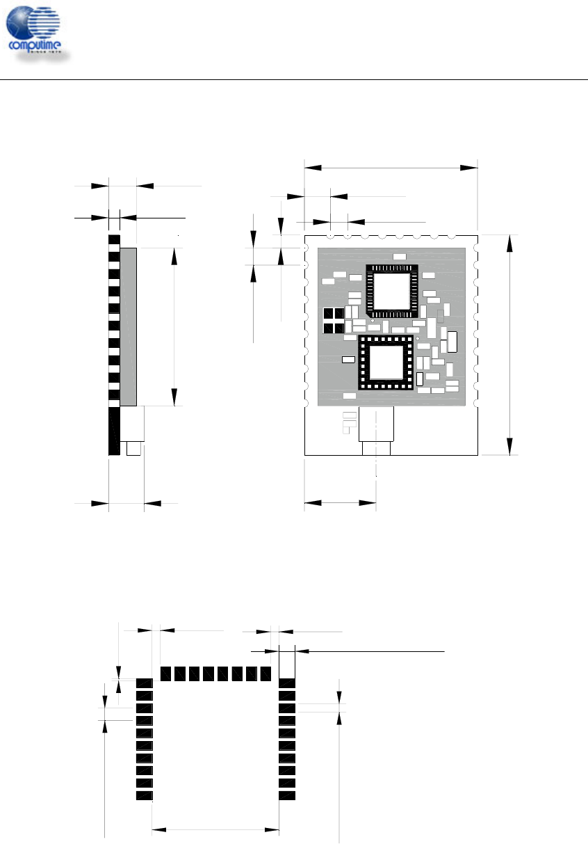
18 Mechanical Dimension
1.6
4.1
5.2
25.4
32.4
10.52
2.54
2.54
1.91
3.81
23.22
2.79Typ 28 pads
1.53
1.53
0.38
1.78Typ 28 pads
22.61
2.54 Pitch Typ
Unit in mm

CT-EM2506 ZigBee Ready RF Transceiver Modules
Computime Ltd. All rights reserved Confidential Page 16 of 16
19 Ordering Information
Ordering Part Number Description
CT-EM2506 ZigBee-ready RF module, 128 KB Flash, PCB trace
antenna, 20dBm output. FCC/CE certificate
20 Document Revision History
Document Revision change
1.0 Draft
1.1 Add MSL
1.2 Modify output power of 2480MHz